Distributed Shared Memory for Real Time Hardware In
the Loop Simulation
by
Timothy Elmer Kalvaitis
Submitted to the Department of Electrical Engineering and Computer Science in partial fulfillment of the requirements for the degrees of
Bachelor of Science and
Master of Science in Electrical Engineering at the
MASSACHUSETTS INSTITUTE OF TECHNOLOGY May 1994
©
Timothy Elmer Kalvaitis, MCMXCIV. All rights reserved.The author hereby grants to MIT permission to reproduce and distribute publicly paper and electronic copies of this thesis document in whole or in part, and to grant
others the right to do so.
Signature of Author /. -... ... '.. ... Department of Electrical Engineerhi4 and Computer Science
/')I1
[
My6,1994
Approved by ...Dave Hauger Technical Supervisor The Charles Stark Draper Laboratory
Certified by ... - ...-.. ...
R. John Hansman Jr. Thesis Supervisor Associate Professopof Aeronau,nd Astronautics
Accepted
by
...
....- ...
VVYWA
Fred r-R. oF0genthaler , Departmental Comqnittee on Grad Students
Distributed Shared Memory for Real Time Hardware In the Loop Simulation
by
Timothy Elmer Kalvaitis
Submitted to the Department of Electrical Engineering and Computer Science on May 6, 1994, in partial fulfillment of the
requirements for the degrees of Bachelor of Science
and
Master of Science in Electrical Engineering
Abstract
This thesis describes a distributed shared memory implementation in the context of a framework designed to simulate six degree of freedom vehicle dynamics and control systems with hardware in the loop in real time. Distributed shared memory creates the illusion of a common address space between simulation processes located on different networked computers.
Direct memory access techniques in the form of memory mapped data structures are applied to the development of an input/output system for the simulation frame-work motivating the use of direct memory access as a paradigm for communication. This concept is extended to shared memory for interprocess communication. Mutual exclusion semaphores and read/write locking are discussed as a solution to the prob-lem of concurrent memory access associated with shared memory communication.
Direct memory access is extended to network communication in the form of dis-tributed shared memory. The primary/secondary copy disdis-tributed database is used as a model for the implementation of distributed shared memory. Concurrency con-trol and memory consistency are discussed. Read/write locking is used to insure local memory consistency and an additional lock type is proposed as a means of en-hancing performance by relaxing the inter-host memory consistency constraint. Time step synchronization of simulations communicating via distributed shared memory is discussed as a method of enforcing inter-host memory consistency when required.
Two examples of the use of distributed shared memory for simulation are provided. Performance of the implementation is evaluated and discussed in terms of both general simulation requirements and the two examples. Two other communication techniques are compared to the direct memory access model for performance, scalability, and extensibility from interprocess to network communication.
Technical Supervisor: Dave Hauger
Title: Principal Member of Technical Staff, Charles Stark Draper Laboratory
Thesis Supervisor: R. John Hansman Jr.
Acknowledgments
First and foremost I would like to thank my wife, Caroline, for what seems like an endless supply of understanding. Without her love and support, I would have been unable to complete my studies at MIT. I look forward to many more wonderful years with her, our daughter Mary Beth, and our son Ricky.
Thanks to all the Sim Lab members at Draper. In particular, I would like to thank Mario Santarelli for giving me the opportunity to pursue this work unencumbered by red tape and beauracracy. Dave Hauger for his sound technical advice and common sense understanding of computing. Bill McKinney for his patience in using (testing) the latest versions of my code and his willingness to listen to my ramblings. John Danis for his conservative approach to problem solving. Thank you to Chris Winters for teaching me the value of detail. To Dave and Chris I am especially indebted. Dave's original VAX simulation framework and Chris' subsequent UNIX design were both truly unique creations. Without the simulation framework this thesis would not have been possible. More important than the professional support I have received from these people has been the personal friendship we have developed over the past three years. For that I will always be grateful.
Finally, I would like to thank Professor Hansman for his candor in reviewing my work as well as his good advice during the writing of this thesis.
This thesis was prepared at The Charles Stark Draper Laboratory, Inc., under Inter-nal Research and Development Project #15104, "Precision Vehicle Positioning and Autonomous Work Systems".
Publication of this thesis does not constitute approval by Draper of the findings or conclusions contained herein. It is published for the exchange and stimulation of ideas.
I hereby assign my copyright of this thesis to The Charles Stark Draper Laboratory, Inc., Cambridge, Massachusetts.
Permission is hereby granted by The Charles Stark Draper Laboratory, Inc., to the Massachusetts Institute of Technology to reproduce any or all of this thesis.
Table of Contents
1 Introduction 13
1.1 Simulation Framework ... 13
1.2 Input/Ouput Requirements ... 14
1.3 Direct Memory Access for Device Communication . . . .... 15
1.4 Direct Memory Access for the Simulation Framework ... 17
2 Implementation 23 2.1 Simulation Framework Database Processor . ... 23
2.2 Structure Maps ... 25
2.3 Shared Memory ... 27
2.4 Concurrent Memory Access ... 32
2.5 Distributed Shared Memory . . . .. .. 35
2.5.1 Design Considerations ... 37
2.5.2 Primary/Secondary Copy Distributed Databases ... 39
2.5.3 Concurrency Control ... 42
2.5.4 Updates ... 45
2.5.5 Synchronization ... 47
3 Examples and Results 53 3.1 Example 1 - Gantry Limit Switches . ... 53
3.2 Example 2 - Simulation of an Autonomous Underwater Vehicle . . . 61
8 Table of Contents
4 Comparison of Other Communication Methods 73
4.1 Interprocess Communication ... 74 4.2 Network Communication ... 79
5 Conclusion 87
A Performance Data 91
List of Figures
1-1 Structure maps and hardware access . . . ... 16
1-2 Structure maps and shared memory ... 18
1-3 Distributed Shared Memory ... 19
1-4 Possible configuration using structure maps, shared memory, and dis-tributed shared memory. Hosts 1 and 3 run the simulation. Host 2 communicates with attached hardware. Hosts 4 and 5 handle graphics intensive display of both hardware and simulation data using simula-tion framework tools ... 21
2-1 Simulation framework processing, representation, and organization. . 24 2-2 Structure maps in the framework. ... . 26
2-3 Structure map to shared memory ... 28
2-4 A structure and its representation in shared memory. ... 31
2-5 Address references from shared memory to process memory. ... 36
2-6 A structure and its representation in distributed shared memory.... 38
2-7 Primary/Secondary organization for distributed shared memory... . 41
2-8 Primary and secondary site lock procedures ... 44
2-9 Synchronization of simulation time steps. ... 49
2-10 Synchronization of simulation time steps using distributed shared mem-ory ... 51
3-1 Gantry hardware configuration. ... 55
10 List of Figures
3-2 Specification of register map for dicrete input board. ... 56
3-3 Specification for motor discretes. ... 57
3-4 Network and process configuration for unmanned undersea vehicle test. 62 3-5 Specification of vehicle state information for display . ... 64
3-6 Specification for calculated viewing option ... 65
3-7 Simulation frequency as a funtion of data size for example two ... 66
3-8 Maximum simulation frequency as a funtion of data size. ... 69
4-1 Point to point communication ... 74
4-2 Client/Server communication. ... 75
4-3 Centralized shared memory communication. . . . 76
List of Tables
3.1 Execution times for example one without hardware access and without distributed shared memory. ... 58 3.2 Execution times for example one with hardware access but without
distributed shared memory. ... 59 3.3 Execution times for example one with both hardware access and
dis-tributed shared memory. ... 60
A.1 Execution time of 6000 time steps measured for varying data size in distributed shared memory for example two. ... 93 A.2 Execution times measured for varying data size in distributed shared
memory. ... 94
Chapter 1
Introduction
This thesis describes a distributed shared memory system as an extension of concepts applied during the development of a generic input/output system for a simulation framework. This chapter motivates the development of distributed shared memory in the context of this framework. Chapter 2 details the implementation of the distributed shared memory system. Chapter 3 relates two examples of its use and discusses the network performance of distributed shared memory. Two other communication tech-niques are compared to shared memory and distributed for performance, scalability, and extensibility from interprocess to network communication in Chapter 4.
1.1 Simulation Framework
The development of the distributed shared memory system described in this thesis took place as part of a more general effort to develop a framework for real time hardware in the loop simulation [10]. This framework was designed to support the simulation of six degree of freedom vehicle dynamics and their associated hardware components. To date the framework has been used to simulate the dynamics of air, land, and undersea vehicles and the dynamics of vehicle-truss interaction in space. In addition, simulation of guidance, navigation and control systems is supported as
Chapter 1. Introduction
is the development of realistic instrumentation for the simulated vehicles.
The framework's existing capability, prior to this thesis, was based on a database preprocessor used to define simulation data structures and generate run time informa-tion describing those data structures. This informainforma-tion provided the basis for analysis tools such as plotting, logging, and profiling, as well as programming and debugging tools used to monitor and manipulate the simulation's data structures at run time. Hierarchical organization of data was used to manage the complexity of large scale simulations. Absent before this thesis was the capability to access hardware in real time.
To meet the goal of hardware in the loop simulation, an input/ouput (I/O) system, fully integrated with the existing framework, was required. During the course of this development, the idea of direct memory access as a means of communication was applied to hardware access and then extended to a more general mechanism for interprocess and network communication within the simulation framework. The remainder of this chapter discusses the requirements for the I/O system, and provides an overview of the development of direct memory access for device, interprocess, and network communication.
1.2 Input/Ouput Requirements
In order to interface with vehicle hardware systems, the following four I/O require-ments were imposed:
1. Real time operation. This requirement was two-fold. First, real time operation
required synchronizing simulation time steps with real time rates. Second, real time operation imposed a speed constraint - the I/O system needed to be as efficient as possible in order to access hardware fast enough to sustain both simulation and device rates. Real time frame rates on the order of 100 Hz or greater were required to support existing simulations. Microsecond access times were required to support
a wide variety of hardware. 14
1.3. Direct Memory Access for Device Communication
2. User level hardware communication. In order to avoid the overhead of operating
system calls and long interrupt latencies associated with device drivers, communica-tion with the hardware at the user process level was required.
3. Support for modular functional models transparent to the simulation.
Modular-ity required the abilModular-ity to interchange models and hardware at any time. Transparency required access to real hardware or models of hardware be indistinguishable from the simulation's point of view. In this way, a simulation can communicate with hardware or models of hardware without the need for special code.
4. Tight integration with the existing simulation framework. The simulation
frame-work already provided several tools uniquely suited for monitoring variables and data structures in a simulation. In order to bring these tools to bear on the I/O problem, tight integration with the framework was required.
These requirements were met by applying the idea of direct memory access as a means to communicate between the simulation framework and hardware devices.
1.3 Direct Memory Access for Device Communication
Direct memory access in the context of this thesis is the communication of data from one process to another through common address space'. The mechanism used to support this communication for the I/O system was the structure map. Structure maps are data structures that have been relocated to arbitrary address space in a way that is transparent to simulation code.For hardware communication, direct access means communicating data from a process on the host to a device attached to a bus occupying some of the host's address space [3, 6]. Figure 1-1 illustrates this type of communication. The simulation is a process on the host that has access to the memory locations used to communicate with the bus. The device occupies a predefined set of addresses on the bus. In order
'This is distinct from the concept of direct memory access (DMA) as a means of asynchronous
communication between a device and its device driver in the host's operating system.
Chapter 1. Introduction
Bus
Figure 1-1: Structure maps and hardware access
to communicate with the device, the simulation simply references the appropriate bus locations via a structure mapped to those locations. Use of the framework to generate the structure map allows the framework tools to directly access the device as well.
Direct memory access through structure mapping satisfied the I/O system require-ments as follows:
1. Direct memory access is efficient. Direct bus access is one of the most
effi-cient ways in which a host can communicate with a device. This efficiency more than satisfied real time speed requirements as bus access times are on the order of microseconds.
2. Direct memory access can be applied from user level programs. Bus addresses
mapped to user process memory are accessible without the need to involve the oper-ating system.
3. Direct memory access enabled support for modular, transparent functional
mod-els of hardware. The hardware processes of Figures 1-2 and 1-3 could either be
com-municating with devices attached to the bus, or simulating those devices. Separating the functionality of the simulation and the hardware at the process level provided a means of modularization. Transparency was obtained because communication occurs through simulation data structures that are mapped to either bus addresses or other
1.4. Direct Memory Access for the Simulation Framework
parts of memory. The framework performs the mapping operation without the need to change simulation code.
4. Direct memory access enabled tight integration of the I/O system with the ex-isting framework. The framework maintains run time information for all simulation
data structures. Direct memory access allowed that information to be extended to bus relocated structure maps. As a result, the framework modeling, analysis, and program debugging tools built on this information were able to be applied to the I/O system.
Application of direct memory access to device communication was the key to sat-isfying the I/O system requirements. During the course of this application, however, it was found that direct memory access as a paradigm for communication was also able to be applied to other areas of the simulation framework.
1.4 Direct Memory Access for the Simulation Framework
The simulation framework's capabilities were extended by applying direct memory access to interprocess and network communication. As with device communication, this concept relies on communicating data from one process to another through com-mon address space. Interprocess communication was implemented through shared memory [1]. Network communication was implemented by extending the concept of shared memory to distributed shared memory.
Figure 1-2 depicts a possible configuration for interprocess communication. There are two processes on the host: one carries out the simulation, the other communi-cates with the hardware. As before, device access is accomplished via structure map to bus addresses. In similar style, communication between the simulation and hard-ware processes is accomplished via structure map to shared memory. More generally, structure maps in shared memory allow communication of data structures between arbitrary processes on the same host.
Communicating data structures between processes on different hosts is the goal of 17
Chapter 1. Introduction
Bus
Figure 1-2: Structure maps and shared memory
distributed shared memory. Mapping structures to shared memory, and maintaining the consistency of copies of that memory over several networked hosts creates the illusion of shared memory over the network. This extension of direct memory access is depicted in Figure 1-3. In this example, the simulation resides on host 1 and, as before, the hardware processes communicates with the device via bus addresses on host 2. Communication of data between the hardware process and the simulation, from the point of view of each process, is identical to shared memory communication. The framework, using its run time representation of simulation data structures, carries out the network communication for each process and insures that the distributed shared memory is consistent between the connected hosts.
The use of direct memory access communication extended the simulation frame-work's capabilities by providing a simple, transparent means of interprocess and net-work communication. Shared memory provided general support for transparent com-munication between processes built with the framework. The hardware process of
1.4. Direct Memory Access for the Simulation Framework
Distributed
Addresses
Figure 1-3: Distributed Shared Memory
Figure 1-2 could easily be another simulation communicating any data structure de-fined using the framework. Distributed shared memory extended this transparent
communication across a network. The hardware process of Figure 1-3 could easily be another simulation sharing information over a network. Communication is simple because the framework handles the communication details - the simulation merely accesses memory.
Transparent network communication through distributed shared memory provided greater access to computational resources. This significantly enhanced the frame-work's capability for simulation. Access to remote hosts and specialized computing equipment is now possible allowing simulation tasks to be assigned to computing equipment best suited for the task. Graphics intensive display can be executed on machines with more graphics capability while another machine, connected to hard-ware, can devote its resources to I/O. Still other machines can be devoted to model computation without loading the I/O or graphics computers.
The framework's run time information of simulation data structures can also be mapped to distributed shared memory allowing one simulation to monitor another simulation without the need for recompilation of either program or a priori knowledge
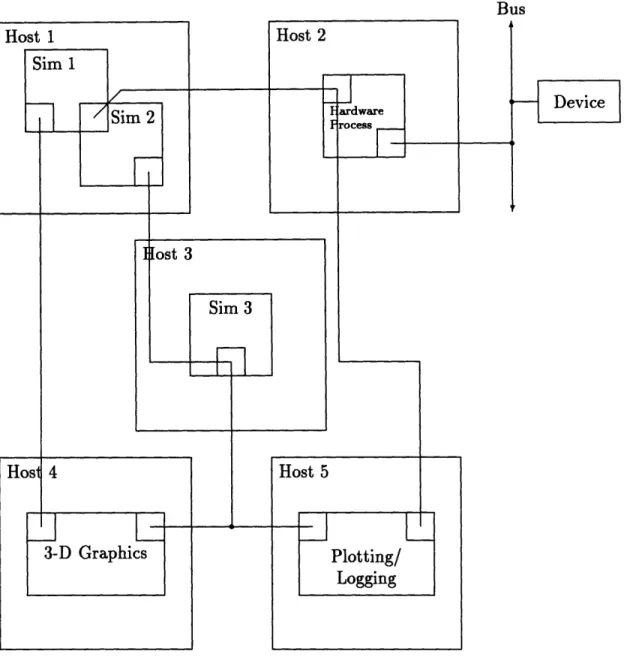
20 Chapter 1. Introduction of the other simulation's data structures. This simplifies source code control (com-mon header files between simulations are not necessary) as well as inter-simulation communication. In short, any simulation can communicate its variables to any other simulation provided they are both built using the framework. Figure 1-4 shows a possible networked configuration utilizing all of the aspects of direct memory access available in the simulation framework.
The remainder of this thesis details the implementation of direct memory access for device, interprocess, and network communication in the context of the simulation framework and provides examples of its use in simulation.
1.4. Direct Memory Access for the Simulation Framework
Bus
Figure 1-4: Possible configuration using structure maps, shared memory, and dis-tributed shared memory. Hosts 1 and 3 run the simulation. Host 2 communicates with attached hardware. Hosts 4 and 5 handle graphics intensive display of both hardware and simulation data using simulation framework tools.
Chapter 2
Implementation
2.1 Simulation Framework Database Processor
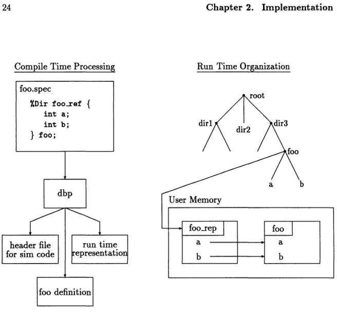
The simulation framework is designed to provide access to data structures used in a simulation implemented using the C programming language. The framework includes a compile time structure preprocessor and a run time simulation environment. Fig-ure 2-1 illustrates the compile time processing and run time organization used by the framework. Data structures are defined in specification (spec) files using a syntax resembling C. A spec file preprocessor called the database processor, or dbp for short, generates three C source files. In Figure 2-1, the file foo.spec defines a data structure called foo-ref and declares the global variable foo to be an instance of that type. The database processor generates a header file, a definition file and a file containing a run time representation of foo. The header file contains the C structure definition for foo.ref and the declaration of the global variable foo. Simulation source files include this header file and access the elements of foo by standard C programming means. The definition file defines the global variable foo and initializes foo with
values specified in the spec file.
The run time representation of foo (called foo rep in Figure 2-1) is contained in the third file. The representation includes information about the location of foo, the
Chapter 2. Implementation
Compile Time Processing Run Time Organization
dbp
header file for sim code
II
run time epresentatio
foo definition
Figure 2-1: Simulation framework processing, representation, and organization.
memory layout, name, type, and size of each of the elements of type fooref, and the position of foo within the run time hierarchy of data structures. The run time organization illustrated in Figure 2-1 shows the conceptual relationship between foo
and foorep. The run time hierarchy contains a pointer to foorep which holds the names and locations of the elements of foo (namely the variables a and b).
The run time simulation environment of the framework is built on the information generated by the database processor. A command interface controls the environment. Access to simulation data structures provides the ability to constantly monitor, log,
foo.snec %Dir fooref { int a; int b; } foo; .-II 24
2.2. Structure Maps
plot and change any variable used in the simulation at run time. This access is accomplished by looking up the name of the global structure in a hierarchy name table and then looking up the name of an element of the structure in its run time representation. For example, access to element a in the structure foo (referred to as foo. a in simulation source code) is accomplished by first locating foorep by the name "foo" in the hierarchy. Once found, foo rep provides the address, type, and size associated with element a which is enough information to access the value of
foo. a.
2.2
Structure Maps
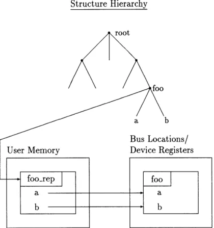
The fact that data structures and their representations are stored separately allows those data structures to be relocated without affecting the framework's run time tools. This fact was exploited in the development of the I/O system in the form of struc-ture maps. A strucstruc-ture map is a data strucstruc-ture that is memory mapped to another location. Device communication is accomplished by reading and writing into a struc-ture that defines the register interface of the device. This strucstruc-ture is then mapped to the bus address of that device'. Figure 2-2 illustrates the relationship between a bus relocated structure map and the run time organization of the framework. In the example, the structure foo, defined in a spec file, has been mapped to a bus location where a and b refer to registers on the device. The run time representation of foo has been altered to reflect the new location of a and b. The structure hierarchy is unchanged.
Structure maps provided efficient accesses to hardware devices from the user pro-cess level on the same host as the simulation. Structure maps also provided the op-portunity to model a device at the register level. Communication between a hardware model and a simulation could occur by monitoring a register definition structure that
1The bus address of a device is generally set by switches or jumpers located on the device. 25
Implementation
Structure Hierarchy
Figure 2-2: Structure maps in the framework. Chapter 2.
2.3. Shared Memory
has not been relocated to bus addresses. However, without the ability to relocate the register definition structures to address space accessible by separate processes, both the hardware model and the simulation needed to be part of the same process. This reduced the transparency of the model. Given that real devices operate in par-allel with the simulation, a transparent model of those devices should also operate in parallel (at least conceptually) in order to be transparent to the simulation. This shortcoming lead to the development of structure maps in shared memory.
2.3 Shared Memory
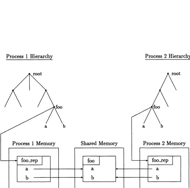
The most straightforward way to provide communication between two simulations using structure maps was to locate the structures in shared memory. Figure 2-3 shows a possible configuration. As with device communication, foo is defined in a spec file and relocated to a new address. With interprocess communication, however, the new address is a shared memory address, accessible from both process 1 and process 2. Both processes have their own run time representations of foo that have been altered to reflect foo's new shared memory location. Modification of a or b by either processes will immediately be seen by the other process.
Structure maps in shared memory provided the capability to develop hardware models that communicate with a simulation using the same register level interface as the real device. As a separate process, these models are conceptually distinct from the simulation in the same manner that the real devices are conceptually distinct. This allowed a model of hardware to be substituted without changing the code used by the simulation to communicate with the device.
As a general mechanism, structure maps in shared memory allowed devices to be modeled at a level higher than the register interface. By defining the hardware to simulation interface at a level higher than the device registers, the simulation could communicate with hardware without requiring device specific information. As an example, suppose an analog to digital converter was attached to the bus of the
Implementation
Process 1 Hierarchy Process 2 Hierarchy
Shared Memory Process 2 Memory
Figure 2-3: Structure map to shared memory.
28 Chapter 2.
.L I
2.3. Shared Memory
simulation host. To communicate with this device, a spec file containing register definitions that control the device and provide the digital voltage values could be defined and mapped to the appropriate bus location. Suppose the digital values on the device are 12 bit integer quantities. To use these values as voltages, they must be converted from 12 bit integers into a floating point value indicating the analog voltage read by the device. If this conversion is done by the simulation, there is no possibility of using a different analog to digital converter. In order to use a more accurate converter (like a 16 bit converter), the simulation code would have to be changed. In addition, any model generating the voltage information would have to be a model of the analog to digital converter - it could not be a model of the analog signal itself as the simulation is expecting a 12 bit integer in a register of the analog to digital converter structure. It would be far more efficient to just generate the floating point voltage directly.
To solve this problem, the simulation could communicate with a process that represents the hardware. The simulation could read floating point voltages from a structure mapped to shared memory while the hardware process communicated with the analog to digital converter via a register definition structure mapped to bus locations. The hardware process would handle the conversion to a floating point voltage value and place the result in shared memory. This would isolate the simulation from hardware changes (like an upgrade to a better converter) as well as provide a mechanism for efficiently modeling the signal coming from the converter - the hardware process could just send floating point voltages without doing any conversion. In addition to device access and hardware models, structure maps in shared mem-ory provided a general mechanism for communicating data between processes devel-oped using the framework since any structure defined in a spec file could be relocated to shared memory. However, while the basic idea of structure maps in shared memory was sound, the implementation was limiting. In order to communicate, two processes had to be compiled with a common spec file that defined the communication interface. 29
Chapter 2. Implementation
This implicitly limited the structures that could be communicated between the two processes to only those known at compile time. While this was not a severe restriction for well defined interfaces like device register specifications, it did not maximize the flexibility available from the framework's run time tools.
As an example, suppose that a hardware process and a simulation process were running on the same machine communicating through shared memory. It would be possible to plot the variables of process 1 using the framework tools from process 1 and it would be possible to plot the variables of process 2 from process 2. It would also be possible to plot the variables in shared memory on these same plots from either process 1 or process 2. However, these would be the only variables in either process for which this was true. It would not be possible to plot a variable from process 2 on a plot of variables from process 1 unless those variables had been defined at compile time as shared variables.
Placing the run time representation of a structure in shared memory along with the structure map itself eliminated this compile time restriction. Figure 2-4 illustrates the resulting organization. In this example, both foo and foorep are placed in shared memory, and the run time hierarchy of both processes are updated to reflect this fact. The effect is to have a part of the hierarchy shared by both processes via shared memory. To set up this configuration, the spec file for foo is compiled into process 1. At run time (via command execution), process 1 places foo and foorep in a predetermined shared memory block. To gain access to foo from process 2, the process maps the known shared memory block into its address space and links the root of the hierarchy (in the case foorep) into its own hierarchy. Once linked, process 2 can apply any of the framework tools to foo.
Placing both the structure map and the run time representation in shared memory provided the ability to communicate any data structure defined in spec files between any number of processes on the same host developed using the framework. Distributed
shared memory, to be described in Section 2.5, extended this capability to processes on 30
2.3. Shared Memory
Process 1 Memory Process 2 Memory
r - - - -…-- - - -…
A
Shared Memory
Figure 2-4: A structure and its representation in shared memory.
31 lot I I I I I I I
II-Chapter 2. Implementation
different hosts. Before discussing the implementation of distributed shared memory, however, it is necessary to point out some of the implementation details of placing structure maps and their representations in address space accessible by concurrent processes. These details apply to both shared and distributed shared memory, and will lay the foundation for much of the discussion of distributed shared memory.
2.4 Concurrent Memory Access
Concurrent processes that access a common address space require concurrency control to prevent simultaneous access to that address space. As an example, recall Figure 2-4. Suppose process 1 always reads foo and process 2 always writes foo. If both of these operations happen concurrently, without control, it is possible for process 1 to read the value of a and process 2 to then write both a and b before process 1 has a chance to read b. If a and b are dependent variables, (such as part of a vehicle state vector), then process 1 will have an inconsistent set of values for a and b. This is particularly a problem for simulation where the set of values in a structure correspond to values for one slice of simulation time. Reading half of the values from one time slice and the other half from another time slice usually causes serious problems in the simulation.
To solve this problem, concurrent access must be controlled. A simple mechanism to accomplish this is a system semaphore [1]. A system semaphore is managed by the operating system to control access to shared resources. To access the shared resource, a process attempts to acquire the semaphore. If it is available, the process proceeds to use the resource. If it is unavailable, the operating system stops the process and queues it to be run when the semaphore becomes available. Once a process is done using the shared resource, the semaphore is released and the resource is made available
to other processes.
A typical implementation of a system semaphore is a counter in the operating system. A process acquires the semaphore by decrementing the counter and releases 32
2.4. Concurrent Memory Access
the semaphore by incrementing the counter. As long as the counter is nonnegative, the process proceeds. If the process decrements the counter to a negative value, the operating system suspends the process until the counter is again nonnegative (i.e. the semaphore is released).
Initializing the counter to a value of one provides mutually exclusive access to a shared resource by several processes. Using a mutual exclusion semaphore is a simple locking strategy. Applied to shared memory, this insures that only one process at a time can either read from or write to that area of memory. This solves the access problem described in the above example. Suppose the semaphore is initialized to one. Process 1 acquires the semaphore by decrementing the counter to zero. Since the value is nonnegative, process 1 proceeds to read a from foo. After process 1 reads a, process 2 attempts to acquire the semaphore protecting foo by decrementing the counter. The resulting value is -1 so the process is suspended. Process 1 then reads b from foo and releases the semaphore by incrementing the counter. This action causes process 2 to wake and write both a and b. Process 2 then releases the semaphore by incrementing the counter. The resulting counter value is one, and the shared memory has been protected.
While a mutual exclusion semaphore can suffice for shared memory access, a more complex scheme was required for the framework in order to take advantage of the type of communication found in simulation. The problem with a mutual exclusion semaphore for simulation is that it is unnecessarily restrictive. Concurrent reading processes must be suspended even if data is not changing in shared memory. As an example, suppose there are three processes. Process 1 and process 2 read from, and process 3 writes to shared memory. If all processes are required to acquire the semaphore before accessing the shared memory, then it is possible, for process 1 to be suspended waiting for process 2 to complete its reading even though process 3 is not waiting to write into the area. It would be more efficient if process 1 and process 2 were both allowed to read concurrently as long as process 3 was not writing into 33
Chapter 2. Implementation
shared memory. This leads to the notion of read and write locks [2, 8].
A read lock is acquired when a process wishes to read from shared memory. A write lock is acquired when a process wishes to write to shared memory. The rules for locking are as follows:
* There are as many read locks as there are processes wishing to access shared memory.
* Only one write lock exists for a shared area.
* Acquiring the write lock prevents read locks from being acquired (as well as other write locks since there is only one write lock).
* Acquiring a read lock prevents a write lock but does not prevent another read lock from being acquired.
Implementation of this form of locking can be done with a system semaphore im-plemented as a counter. The counter's initial value is equal to the maximum number of processes allowed to simultaneously read the shared area. A process acquires a read lock by decrementing the counter by one and releases the lock by incrementing the counter by one. A process acquires a write lock by decrementing the counter by its initial value and releases the lock by incrementing it by that value. For example, if the counter is initialized to ten, a write lock is acquired by decrementing the counter by ten and released by incrementing by ten. As with the mutual exclusion semaphore, a process is suspended and queued if the counter becomes negative.
Read/write locking is more efficient for processes that access shared memory such that there is one writer and multiple readers by allowing multiple reads to execute concurrently. Since this sort of communication was typical for simulations built with the simulation framework, read/write locks were used for concurrency control for shared memory.
In addition to concurrency control, placing structure maps and their represen-tations in shared memory required that all pointer references located in the shared 34
2.5. Distributed Shared Memory
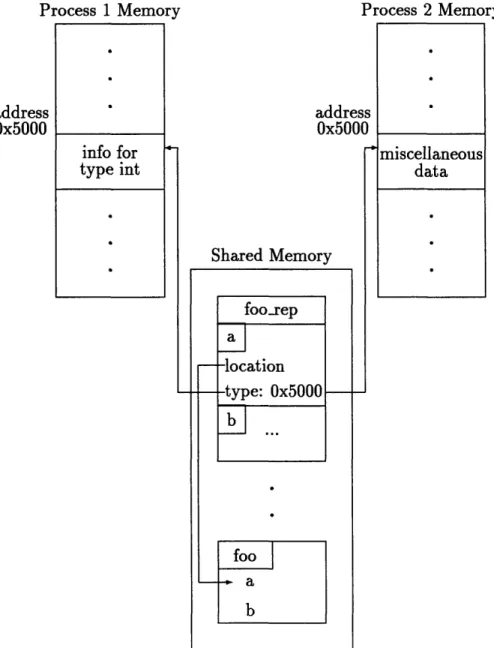
block were references into that same block and not into process specific address space. Figure 2-5 demonstrates the problem. Again, fooxrep and foo are located in shared memory. Recall that the framework generates type information as well as the location of each element of foo. Figure 2-5 shows the entry in f oo-rep for element a. The location field is a pointer to element a in foo. Since this address is located in the shared block, both processes can successfully dereference the address to obtain the value contained in a.
Suppose, however, that foo originated in process 1 and was relocated to shared memory with only the location fields of foo.rep altered to point into shared mem-ory. In this case, the type field for a in foorep would contain a pointer reference to an address in process 's address space (location 0x5000 in this case). If process 2 attempts to use this information by dereferencing the pointer, either the operating system will signal an error because the address dereferenced does not exist in pro-cess 2's address space, or, as shown in Figure 2-5, the address does exist in propro-cess 2's address space, but some random information (almost certainly not the correct in-formation) is located at that address. In this case, unpredictable results will occur.
To prevent this kind of addressing problem, it is essential that all pointers with the potential to be dereferenced from several processes hold addresses of locations in shared memory. For the framework this implied moving all supporting structures (such as type and unit information) into shared memory. This insured that any processes that had access to the shared area could dereference any address contained in that area.
2.5 Distributed Shared Memory
Distributed shared memory in the context of the simulation framework is an exten-sion of the shared memory implementation to network communication. Figure 2-6 illustrates the basic concept for a two host configuration. In this example, the
Implementation
Process 1 Memory Process 2 Memory
address 0x5000
Shared Memory
miscellaneous data
Figure 2-5: Address references from shared memory to process memory. address xfi000 info for type int 4-foorep a -location -type: 0x5000 b ... foo a b 36 Chapter 2.
T
V.VVV2.5. Distributed Shared Memory
cesses of Figure 2-4 are located on two machines connected by a network line. On both machines, a block of shared memory exists that contains the structure foo and its framework representation foo.rep. As with the shared memory implementation, the hierarchy of both processes is altered to reflect the new location of foo in shared memory. The distributed shared memory implementation, however, has the added task of insuring that the shared memory on host 1 is consistent with the shared mem-ory on host 2. In this way, access to foo from the perspective of either process 1 or process 2 is identical to the shared memory access previously described. The following sections describe the design and implementation of distributed shared memory.
2.5.1 Design Considerations
The simulation framework was designed to support real time hardware in the loop simulation as defined in chapter 1. In order to be a practical piece of the framework, the implementation of distributed shared memory needed to be efficient and inter-changeable with the shared memory interface. Network update times needed to be as efficient as possible to meet the 100 Hz frame rates supported by the framework. Similarly, network overhead for concurrency control needed to be minimized, espe-cially given the relative infrequency of concurrency conflicts for the kind of simulation supported by the framework. As an extension of shared memory, distributed shared memory needed to have the same programmatic interface as shared memory so that the communicating processes could be assigned to a single host or multiple hosts without recompilation.
An important design consideration in meeting these two goals was to take advan-tage of the uniqueness of simulation communication as it existed for the framework. These simulations generally communicate in one direction. Most applications require one writer and multiple readers (for example, the simulation as a writer, and several graphics processes as readers). Exploiting this fact both simplified the design and resulted in high efficiency for the most common configuration. Also important was 37
Implementation
Host 1 (Primary)
Host 2 (Secondary)
Figure 2-6: A structure and its representation in distributed shared memory.
38 Chapter 2.
2.5. Distributed Shared Memory
recognizing that distributed shared memory in the context of the simulation frame-work need not be concerned with the types of issues related to operating system support for distributed shared memory. At the operating system level, very little is known about the kind of data stored in a shared area and the kinds of access patterns that data will have. As a result, no assumptions can be made that might increase the efficiency of the implementation. Conversely, the framework, as a tool for a particular class of simulation problems holds a lot of information that was able to be applied to the design of distributed shared memory.
2.5.2 Primary/Secondary Copy Distributed Databases
A useful perspective in the design of distributed shared memory was to view the simulation framework as a database of data structures. Structure representations in a hierarchical organization amounted to a form of database organization with each structure comprising a record in the database. Given this perspective, distributed shared memory could be viewed as a type of distributed database problem. As such, this perspective suggested a solution from distributed database technology. Specifi-cally, a form of distributed database implementation that utilizes a primary copy of the database and several secondary copies [8]. In this type of implementation, the primary copy, by definition, is always up to date and holds the current version of the data in the database. The secondary copies are duplicates of the primary copy. Only the primary copy is allowed to be modified. Once modified, the secondary copies are sent updates to insure their consistency with the primary site. The secondary sites modify the database by first sending a lock request to the primary site, then sending the modification. Once received at the primary site, the modification is disemminated to the remaining secondary sites.
There are advantages and disadvantages associated with the primary/secondary implementation versus alternative implementations. The main advantage is locking efficiency [8]. Since all transactions go through the primary site, a lock request from 39
Chapter 2. Implementation
a secondary site requires communication with only the primary site2. Locking is even more efficient if the lock originates at the primary site since no network traffic is required to obtain the lock. If the processes at the secondary site are generally reading the database, and only the processes at the primary site are writing, there is very little network overhead for concurrency control. This fit the common configuration for simulations using the framework.
Fortunately, the disadvantages of the primary/secondary copy implementation versus other distributed database designs did not apply to the simulation framework. The main problem with the primary/secondary implementation from a database per-spective is that it is vulnerable to primary site failure [8]. For database applications that require consistency over a long period of time, this can mean possible data loss.
Loss of data in simulation, however, is not a problem. Simulation variables are not persistent, and simulations are designed to be repeatable. As a result, all simulation data placed in distributed shared memory can be reproduced by simply rerunning the simulation. If the primary site fails, it is generally a simple matter to restart the simulation using a different primary site.
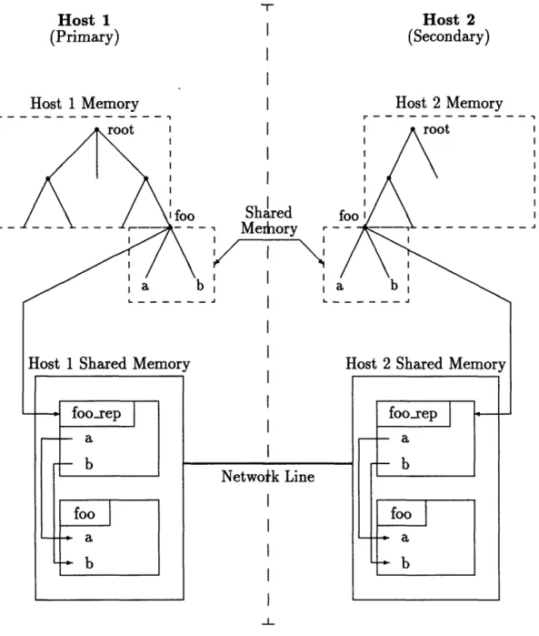
Given the efficiency and lack of applicable disadvantages with respect to the alter-natives, the primary/secondary site distributed database became the paradigm for the distributed shared memory design in the framework. Figure 2-7 illustrates a typical configuration. One host acts as the primary site with a shared memory block on that site comprising the primary copy of the area. Other hosts connected to the area are secondary sites each holding a copy of the primary area in shared memory. A process at the primary site satisfies secondary lock requests and sends network updates to the secondary sites. A process on each secondary host receives updates from the primary site and places them in shared memory to insure consistency with the primary copy. Details of the locking protocol for concurrency control and the update procedure are contained in the following two sections.
20Other, more complex locking protocols require communication between several sites.
2.5. Distributed Shared Memory 41
Primary Host Network Secondary Host
Figure 2-7: Primary/Secondary organization for distributed shared memory.
Chapter 2. Implementation
2.5.3 Concurrency Control
The read/write locks described in Section 2.4 for shared memory required modification when applied to distributed shared memory. The primary/secondary organization for a distributed database requires that lock requests be made through the primary site. Making requests to the primary site will insure that the secondary sites are always consistent with the primary. This form of read/write locking, however, is potentially inefficient, especially for processes that can relax the consistency constraint.
To understand the inefficiency, recall the configuration of Figure 2-7. If read locks must be acquired from the primary host, then a write lock on the primary host will cause all secondary host processes requesting a read lock to suspend operation until the write lock at the primary site is released. This is inefficient for two reasons. First, a read lock request requires network communication to the primary site which can be slow. In addition, requiring consistency between the primary and secondary copies at all times is not generally required for simulation framework applications.
Recall that for shared memory the goal of concurrency control is to insure that the data contained in a shared block always comprise a self consistent set. Extending this constraint to distributed shared memory implies that each copy of the shared area always comprise a self consistent set and that they are all the same set. This is an unnecessarily tight constraint for simulation. The reason for this is that synchro-nization of network processes with each other is not usually necessary as each process requires only one set of data in distributed shared memory to operate.
For example, suppose the primary host is executing a vehicle simulation, and a secondary host is displaying the vehicle. The only data required to display the vehicle would be the state vector of the vehicle. It is not necessary that the display always have the state vector for the same time step as the simulation. It is only necessary that the data in distributed shared memory be a complete state vector for a given time step. For this reason it is possible to relax the consistency constraint by requiring that each copy of the shared area must always comprise a self consistent set locally. 42
2.5. Distributed Shared Memory
The relaxed constraint, however, does not require that each copy be the same at all times3 .
In order to take advantage of the fact that the consistency constraint could be relaxed for most applications, a third type of lock was added to the locking mechanism
- the network lock. The network lock is a lock at the primary site that is requested by a secondary site before requesting a write lock. It is used to signify that a write to a secondary copy is about to take place and that an update from the secondary site will require a write lock at the primary site in the future. The network lock rules added to the read/write lock rules are:
* There is one network lock and it resides at the primary site.
* Acquiring the write lock at the primary site requires acquiring the network lock first (whether or not the request comes from the primary or secondary site).
* Acquiring a network lock from a secondary site prevents acquisition of a write lock at the primary site, and prevents acquisition of the network lock by another
secondary site, but does not prevent read locks at any of the sites.
* Obtaining a write lock at the primary site prevents acquisition of the network lock and prevents read locks at the primary site, but does not prevent read locks at secondary sites.
The network lock is the only lock that is specific to the primary site. Each site has its own local read and write locks to protect the shared memory blocks. Figure 2-8 illustrates the procedure for obtaining read and write locks at both primary and secondary sites. At both primary and secondary sites a read lock is acquired by acquiring the local read lock. A write lock request from a process at the primary site is obtained by first acquiring the network lock then the local write lock. Once data is written in the primary copy, updates are sent to the secondary sites.
3Section 2.5.5 describes support for applications that cannot relax the consistency constraint.
Chapter 2. Implementation
Primary Site Lock Requests Secondary Site Lock Requests
Read Lock:
Acquire local read lock. Read data.
Release local read lock.
Write lock:
Acquire network lock. Acquire local write lock.
Write data.
Update secondaries. Release local write lock. Release network lock.
Read Lock:
Acquire local read lock. Read data.
Release local read lock.
Write lock:
Acquire primary network lock. Acquire local write lock.
Write data.
Update primary site. Release local write lock. Release primary network lock.
Figure 2-8: Primary and secondary site lock procedures.
At a secondary site, a write lock is obtained by first requesting the network lock from the primary site, then acquiring the local (secondary) write lock. Once the data is written to the secondary copy, it is sent back to the primary site where it is placed in shared memory by obtaining the primary site write lock, writing the data, and updating the other secondary copies.
The efficiency of the read/write/network lock strategy comes from the fact read locks at one site do not affect other sites and do not require network communication. A write lock at the primary site prevents read locks at that site and prevents network locks, but does not prevent read locks at the secondary sites. This allows secondary site processes requiring only read locks to continue processing during a primary site write lock. Similarly, the network lock does not prevent read locks at the primary
site which allows primary site processes to continue execution without waiting for the pending update from the secondary holding the network lock.
2.5. Distributed Shared Memory
The cost of this strategy is the fact the the primary and secondary copies are not
guaranteed to be identical to each other at all times. This is a direct result of relaxing
the consistency constraint. It is possible for a secondary site to read its copy while the primary site changes its copy. This is slightly different behavior than simple shared memory. For shared memory, it is not possible for any other process to perform a read while a write is being performed (as long as read/write locking is used). If this were allowed, the reading process might get inconsistent data from the shared block. For simulation this usually means reading the shared block and getting half of the data from one time step and half from another.
Since the secondary sites in distributed shared memory actually have physically different copies, however, this is not a problem. As long as local read/write locks insure the self-consistency of each shared block, the penalty for changing the primary site in parallel with reading a secondary site is a delay in receiving the information at the secondary site. This is a penalty only if the application requires that distributed shared memory act exactly like shared memory. In this case, allowing a read while the primary site was being written would be viewed as reading a bad value since, in simple shared memory, once the write has occurred, it is not possible to read the old value.
For the simulations built with the framework, however, it was sufficient to insure that local shared areas were self consistent without requiring that they be identical to the primary copy before allowing a read. For the framework implementation, read/write locking was used to insure local self-consistency, and the network lock in conjunction with the primary site write lock procedure was used to insure that the updates reached all sites.
2.5.4 Updates
The primary/secondary copy implementation required a procedure to update sec-ondary copies with primary copy changes. There were several possibilities. One was 45
Chapter 2. Implementation
to send an entire copy of the shared area to each secondary when a primary site write lock was released. While this is a simple solution, it carries a significant efficiency cost as large amounts of data, most of which already exists at the secondary sites, need to be communicated over the network every simulation time step.
Another alternative was to create a mechanism that detected the changes made to the shared area after releasing a write lock and send only the changes in updates to the secondary sites. While this is more efficient than sending the entire area every time step, it is still inefficient because there is no way for a general facility like the framework to predict the changes made to a shared area as they differ from simulation to simulation. As a result, only a memory comparison function executed every simulation time step would suffice. If the shared area is relatively large, this is a very expensive operation.
The solution used for the distributed shared memory implementation was to re-quire writing processes to specify the changes made to the shared area. Once specified, the framework sends the updates to the secondary sites. This solution has the disad-vantage of requiring extra bookkeeping on the part of the user, however it has several advantages that need to be weighed against this disadvantage.
The primary advantage is efficiency. The user is in the best position to decide what changes were made between the acquisition and release of a write lock since the user must specify those changes to begin with. The user can generally identify the difference from time step to time step without doing a memory comparison on the entire area and without sending the entire area over the network.
Similarly, the user can decide when to update the data. The user can take ad-vantage of the relaxed consistency constraint for the shared area at the primary site without immediately sending an update. This minimizes network traffic by reducing the update frequency to only that required by the user. It also reduces memory re-quirements because the user can use the shared memory area without keeping a local working copy.
2.5. Distributed Shared Memory
Finally, the framework run time data structure representations minimize the book-keeping overhead required on the part of the user. Since there is both size and location information of every data structure located in the shared area, all that is required for update bookkeeping is a pointer to the framework representation of each data structure needing an update4. To perform an update, only the pointers of the rep-resentations need to be passed to the framework. The framework then uses that information to send the actual structure and its identifier to the secondary sites. At the secondary site the identifier is used to locate the local framework representation. Once found, the size and location of the incoming data is known, and the update is performed at the secondary site. The network update overhead per data structure is only the one word used as the identifier - the rest of the update is modified data.
2.5.5 Synchronization
Synchronization in the context of the simulation framework is the process of linking one simulation's time steps with another. This is necessary in the case of distributed simulation. Suppose two processes are responsible for part of the computation of a simulation time step. Suppose further that process 2 needs to wait for process 1 to finish (so that it can get some data from that process) but process 1 does not need to wait for data from process 2. If the data is communicated through shared memory then process 1 is a writer and process 2 is a reader.
Figure 2-9 illustrates three possible synchronization states for the two processes. Each plot shows process 1 on the top and process 2 on the bottom. Process 1 writes and process 2 reads are shown versus time. Also shown are the simulation time steps (labeled to, tl, etc). Note that reads are generally performed at the beginning of the time step while writes are done at the end of the time step. The top plot shows process 1 and process 2 running asynchronously. One problem shown is that process 1
4It is also possible to keep pointers to individual fields within a data structure, but this is somewhat less efficient in practice.
Chapter 2. Implementation
can perform two writes (W1 and W2) in between two process 2 reads (Ro and R1).
Synchronous operation requires that there be one read for each write.
The second plot shows one solution to this problem. Process one is synchronized with process two such that they are running serially. This means that process 1 executes time step to while process 2 waits. Then process 2 executes its part of time step to while process 1 waits. In this way there is one read for each write and the simulation time steps are synchronized. This is not a particularly efficient solution. Since process 1 does not rely on data from process 2 there is no reason for it to wait for process 2 to complete its time step before performing the next one (although we still do not want it to execute two time steps before process 2 completes one). As a result, it is possible for both processes to operate synchronously, but in parallel.
This solution is a form of pipelining commonly used in microprocessors to paral-lelize instruction execution [9]. Plot three illustrates the result. Process 1 performs its part of time step to while process 2 waits. Once complete, process 2 starts its part of time step to. At the same time, process 2 begins execution of time step tl. From
then on, both processes perform their part of a time step in parallel. Note that there is still only one read for every write, and that the two processes are synchronized.
Figure 2-10 illustrates the same problem using distributed shared memory for interprocess communication. In this case, process 1 is on the primary host and process two is on a secondary host. The plots again indicate reads, writes, and time steps for each process. However, unlike simple shared memory, there is the added difference that a write at the primary site does not reach the secondary site immediately. As a result, a write operation has an associated update operation that occurs some time after the write.
The top plot shows the two processes running asynchronously. As before, there is still the problem of two writes (W1 and W2) in between two process 2 reads (this
time R1 and R2). There is also an added problem - a process 2 read (Ro) between
a process 1 write and its update (Wo and Uo). This is a problem because process 2 is 48
2.5. Distributed Shared Memory Wo Process 1: to Process 2: W1
tl
Ro to Asynchronoust
R1 WotoI
ti W I s Serial Synchronizationt
to Wo W1 W2 W3 to tl t2 t3 I Pipelined Synchronization toI
tl t2 Ro R1 R2 R3 t t,: time step nW, : Write to shared memory for time step n R : Read from shared memory for time step n
Figure 2-9: Synchronization of simulation time steps. Process 1: Process 2: Process 1: Process 2: · ! · ! It~~~~~~~~~~~~~~~~~~~~~~~~~~~ w 49 F11