Publisher’s version / Version de l'éditeur:
ASTM Special Technical Publication, 312, pp. 66-77, 1962-08-01
READ THESE TERMS AND CONDITIONS CAREFULLY BEFORE USING THIS WEBSITE.
https://nrc-publications.canada.ca/eng/copyright
Vous avez des questions? Nous pouvons vous aider. Pour communiquer directement avec un auteur, consultez la
première page de la revue dans laquelle son article a été publié afin de trouver ses coordonnées. Si vous n’arrivez pas à les repérer, communiquez avec nous à PublicationsArchive-ArchivesPublications@nrc-cnrc.gc.ca.
Questions? Contact the NRC Publications Archive team at
PublicationsArchive-ArchivesPublications@nrc-cnrc.gc.ca. If you wish to email the authors directly, please see the first page of the publication for their contact information.
NRC Publications Archive
Archives des publications du CNRC
This publication could be one of several versions: author’s original, accepted manuscript or the publisher’s version. / La version de cette publication peut être l’une des suivantes : la version prépublication de l’auteur, la version acceptée du manuscrit ou la version de l’éditeur.
Access and use of this website and the material on it are subject to the Terms and Conditions set forth at
Loading tests on full scale house roofs
Thorburn, H. J.; Schriever, W. R.
https://publications-cnrc.canada.ca/fra/droits
L’accès à ce site Web et l’utilisation de son contenu sont assujettis aux conditions présentées dans le site LISEZ CES CONDITIONS ATTENTIVEMENT AVANT D’UTILISER CE SITE WEB.
NRC Publications Record / Notice d'Archives des publications de CNRC:
https://nrc-publications.canada.ca/eng/view/object/?id=6dcccc28-d42c-410f-b542-7340bd8502c8 https://publications-cnrc.canada.ca/fra/voir/objet/?id=6dcccc28-d42c-410f-b542-7340bd8502c8Ser
TH1
N21r2
no.
165
c.2
C A N A D ADIVISION O F BUILDING RESEARCH
LOADING TESTS ON FULL-SCALE
HOUSE ROOFS
BY
H. J. T H O R B U R N A N D W. R. S C H R I E V E R
R E P R I N T E D F R O M
A M E R I C A N SOCIETY FOR TESTING A N D MATERIALS SPECIAL T E C H N I C A L P U B L I C A T I O N N O . 312 P. 67
-
77.R E S E A R C H PAPER N O . 165
OF T H E
DIVISION O F BUILDING RESEARCH
OTTAWA AUGUST 1962
T h i s publication i s being d i s t r i b u t e d by the Division of Building R e s e a r c h of t h e National R e s e a r c h Council. It should not be r e p r o d u c e d in whole o r in p a r t , without p e r m i s
-
s i o n of the o r i g i n a l p u b l i s h e r . T h e Division would be glad to be of a s s i s t a n c e in obtaining s u c h p e r m i s s i o n .P u b l i c a t i o n s of the Division of Building R e s e a r c h may be obtained by m a i l i n g the a p p r o p r i a t e r e m i t t a n c e , ( a Bank, E x p r e s s , o r P o s t Office Maney O r d e r o r a cheque m a d e pay- able a t p a r in Ottawa, to the R e c e i v e r G e n e r a l of Canada, c r e d i t National R e s e a r c h Council) to the National R e s e a r c h Council, Ottawa. S t a m p s a r e n o t a c c e p t a b l e .
A coupon s y s t e m h a s been i n t r o d u c e d to m a k e pay- m e n t s for publications r e l a t i v e l y s i m p l e . C ~ u p o n s a r e avail- a b l e in d e n o m i n a t i o n s of 5 , 2 5 and 50 c e n t s , and m a y b e ob- tained by m a k i n g a r e m i t t a n c e a s i n d i c a t e d above. T h e s e coupons m a y be u s e d f o r the p u r c h a s e of a l l National R e s e a r c h Council publications including s p e c i f i c a t i o n s of the Canadian G o v e r n m e n t Specifications B o a r d .
Authorized Rcnrint from the Convricrlrtcd Symposium o n Testing Building CbisGuction
Special Teck~ricnl P~rblicn/zo,r iVo. 313
A N A L Y Z E D
Published bv thrLOADING TESTS O N FULL-SCALE HOUSE ROOFS
BY
H . J. THORBURN~ .ANDW.
R. SCRRIEVER~Earlier loading tests on single roof frames had sho~vn that many conven- tional rafter-and-joist frames had iailure loads tvell below the design snotv loads specified in Canada. This suggested that either actual sno\v loads were lower than the design values or that the strength of individual roof frames do not indicate full strength of the complete roof. Consecluently, a number oi full-scale house roofs were load tested to failure in the laboratory to determine what additional strength is derived fro111 the roof sheathing providing the roof with "folded plate action." The results indicate that on the whole most roofs do not derive much extra strength from the sheathing.
House structures as they are known today have developed largely on the basis of tradition and experience. Unlike larger buildings and other structures, they do not generally lend themselves to the normal methods of structural design. As a result, adequate strength of the structures had to be obtained initially by a "cut and try" process and subse- cl;ently by patterning the designs after those which had given satisfactory per- formance. Some components of the structures could be analyzed. For many years these have been designed on the basis of certain minimum dcsign loads, maximum stresses, and acceptable per- formance. For many components, how- ever, such criteria have not been gener- ally established, and the design and acceptance must be based primarily on experience. Consequently, whenever a change in the traditional methods of construction is considered, the structural
1 Building Structures Section, Division of
Building Research, National Research Council, Ottawa, Canada.
effect and merit of the change cannot always be easily and cluickly evaluated.
Such a problem of a new design arose when the Division of Building Research of the National Research Council of Canada became concerned ~vith the evaluation of light wooden 11'-trusses for house roofs. Although 11'-trusses can be analyzed readily and therefore de- signed and evaluated according to nor- mal engineering methods, i t x a s found that trusses so designed n ere, in general, much stronger than conventional roof frames. As both trusses a n d conven- tional roof frames have to support the same loads, there is obviously an in- consistency in the strength require- ments of the two systems. Since well- built conventional joist and rafter roofs have, generally, a record of satisfactory performance, there mould seem to be no need for trusses to be stronger than the conventional systems they would re- place. I t was therefore decided that trusses would be designed a n d evaluated on the basis that they rrould provide
performance equivalent to that of the better types of conventional construc- tion.
Since only limited information was available on the performance of conven- tional systems ( l , ~ ) , ? the Division of Building Research, in cooperation with the Forest Products Laboratories of Canada, undertook a program of loading tests on several types of cocventional roof frames. These tests, which were carried out on pairs of frames loaded b y means of hydraulic jacks, indicated t h a t roof frames in common use in Canada had failure loads varying all the way from 20 to 140 lb per scl ft, \\lit11 those of the better types of constructioll in the 100 lb per sq ft range. On the basis of this information, it was decided t h a t W-trusses would be recluired to carry a t least 100 lb per sq f t before failure. This load-carrying capacity of 100 lb per sq f t was considered satisfactory for areas ivith design snow loads up to 50 lb per sq ft. Thus, with trusses required t o carry a t least 100 lb per sq f t , a mini- mum load factor of 2 has been implicitly established with regard to the present design snoiv loads. I t \vill be recognized t h a t this represents a significant depar- ture from the load faclors of 3 or 4 nor- mally found in timber construction. Al- though the important cluestion of load factors, particularly those used in house design, deserves much discussion, it is a matter outside the scope of this paper.
Of immediate concern are the low capacities of the weaker conventional frames. If these types of construction are used extensively, and several held investigations have indicated t h a t they are, then a significant cluestion is raised. Since some types of roof frames have failure loads in the range of 20 to 50 l b per sq f t and the design snow loads speci- fied in the National Building Code of
"The boldfaee llumbels In r)alrllthcaea refer t o the 11st of ~efelenees appended t o thls papel
Canada3 range from 30 to 50 Ib per scl f t in the heavily populated areas (and higher in some other areas), why have there not beell more numerous house roof failures in Canada?
There seem to be two, or a combina- tion of two, possible answers to this question. First, it may be t h a t the snow loads that actually occur on roofs are substantially less than the design values specified in the Building Code, or second, it m a y be t h a t loading tests carried out on conventional frames do n o t indicate the true strength of a complete roof. Possibly the sheathing which covers the frames provides additional strength b y acting as a "deep beam" on each slope or b y folded-plate action a n d perhaps the gables also contribute significantly to the strength.
Both of these factors are being investi- gated. I t is hoped t h a t useful informa- tion on snow loads will be gained from a survey of these loads on roofs all across Canada t h a t the Division h a s been con- ducting since 1956 (3). T h i s survey, \\lhich is being carried out primarily t o provide a more rational basis for design snow loads in the National Building Code of Canada, now comprises ob- servations of actual snow loads on more than 100 roofs in Canada. Additional in- formation is also being gained from stud- ies of a number of roof failures from snow loads (3). Although the survey is i n its fifth winter. final quantitative con- clusions canno; yet be drawn because of the variable nature of snow loads.
Investigation of loading tests of roof componeilts promises to bring more iin- mediate results, since this lends itself more readily to analysis and experiment. One obvious part of such a n investiga- tion involves the load testing of full-
3 Natiolial Building Code of Canada, 1953, Xssoeiate Comrnitter 011 t h e National Building
Code, National Jtescalch Council, Ottnwn, Callads (1953).
scale house roofs, which this paper de- scribes.
TEST STRUCTURES
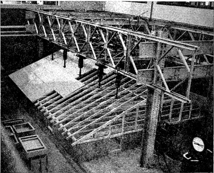
The type and size of the eight full- scale roof structures tested in the labora- tory were governed by two main factors. First, to provide information on the effects of the sheathing and gables, it was essential that the construction used in
the same over-all size and also had the same arrangement of members. Each frame had a span of 24 f t and a slope of 5 in 12, and consisted of a pair of rafters, a pair of joists, and a rafter or collar tie (Figs. 1 and 2). The rafters were joined at their upper ends tlirough a ridge board and were supported a t their lower ends on exterior side walls. The joists, which were spliced a t the mid-point over
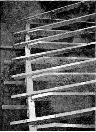
FIG. 2.-Ply11-00d-S11eathed Roof Under Construction Showing Details of Framing and Sheath-
lng.
the complete roofs be the same as that used in the earlier tests on single frames (2). Secondly, it was desirable that the complete roof be as representative of full-scale roofs as conditions \vould allow in order to make the results as valid as possible. On these bases, the eight test roofs were constructed as follows.
The test structures were simple gable roofs each of the same span, length, a n d slope. The frames of all roofs thus had
a simulated center partition, tied the lower ends of the rafters together. Simi- larly, the collar ties connected the mid- spans of the rafters together. All mem- bers were No. 1 (Construction) Eastern spruce lumber, 2 by 4's a n d 2 by G's being used for rafters, 2 by 6's for joists, 2 by 4's for collar ties, and 1-in. material for ridge boards. I n each roof, the frames were placed 16 in. on centers and had a continuous 1 by 4 i n . ribbon strip con- necting the centers of all collar ties. The
ribbon strip was necessary because, in spite of their name, collar ties used a s intermediate rafter supports usually a c t in compression when the frames are loaded and thus tend to buckle. This tendency is aggravated b y the eccentric connections of the collars to the rafters.
The length of the complete roof was not governed b y the previous single frame tests, escept that the length was not to be less than the span. An upper
situation existing in a house, however, lies between these extremes, the actual condition being determined b y the type of construction and the locations of in- terior partitions which meet the esterior side walls. Since there are no apparent average or typical conditions, it was de- cided to support the test structures on low walls, which were fixed a t their ends and free a t their centers, only to the es- tent t h a t their own stiffness ~vould allow.
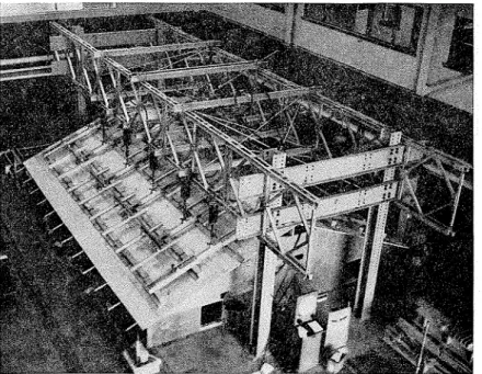
FIG. 3.-Board-Sheathecl Roof Ready for Tcsting.
limit on the length was imposed b y the available laboratory space and loading capacity. I n view of these limits and the requirement that the test structures be as representative of full-scale roofs a s possible, the length was set a t 30 ft.
The support conditions provided for the roof a t the side walls were selected on the following basis. I n the tests on single frames, the two extreme conditions were used: some frames were supported on rollers which gave complete freedom and others were completely fixed. T h e
The center partition was similarly fixed a t the ends. The height of all ~valls was arbitrarily set a t 2 f t on the assumption that a n y variations caused b y different heights would be of little importance.
Within the limits alloived b y the single frame tests, several features of the eight test structures were treated a s variables. The size of the rafters was one of these, 2 by 4's being used in sis roofs and 2 by 6's in the other two. Another variable was the through nailing a t the joist splice and the heel joint using 3i-in.
(16 d) common nails. Three nails, as re- quired by the National Building Code (1953)3 were used a t these joints for four roofs; four nails, as required in the 1960 revision of the Code,4 were used in two roofs; and no nails and six nails were used to compare flexible and stiff roofs. T h e toe nailing a t these joints was kept constant. The only other variable, and one which was not governed b y the previous tests, was the sheathing applied
tain roofs built to "average" standards, and, equally important, an attempt was made to be consistent in these standards.
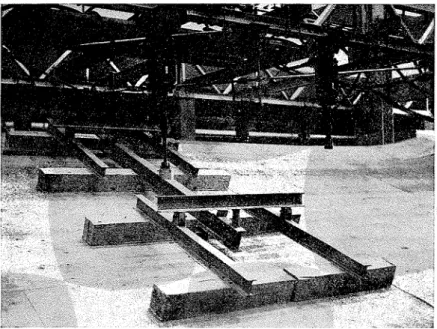
Loading conditions were t h e same as those in the tests on single frames: eight concentrated loads applied t o the rafters a t the center of each eighth of the span (Fig. 1). Expanded to cover the com- plete roof, this arrangement consisted
FIG. 4.-Hydraulic Jack Loatling Divided into Four Equal Line Loads by Whiffletrees.
to the rafters. I t was either 4 by 8-ft sheets of 3-in. plywood nailed a t 6 and 12 in. intervals a t edge and interior supports, respectively, or
2
b y 6-in. square-edge boards nailed with two nails per board a t each support. I n both cases 2-in. common nails were used.I n the co~lstruction of the eight test structures, average materials and work- manship were used in an attempt to ob-
.' National Building Cocle of Canada,
1960,Associate Committee on t h e National Building Code, National Research Council, Ottawa, Canada (1960).
of eight equally spaced line loads parallel to the ridge.
The loading system consisted of a re- action frame~vork (Fig. 3) (4), hydraulic jacks, and load-distributing whiffletrees (Fig. 4). T h e reaction framework was made of a pair of columns a t each end of the roof and a pair of trusses supported by the columns. The trusses, which were Bailey bridge trusses, spanned over the roof between the pairs of columns and ran parallel to the ridge in positions directly over the quarter points of the
roof span. Six hydraulic jacks, which provided the actual loading force, were suspended from the lower chord of each of these trusses, each jack being posi- tioned along the chord over the center of an area of roof proportional to the jack capacity. From this position over each slope, the load from each jack was divided by a whiffletree into four equal line loads. The application of the load to the roof was made through felt-cov- ered blocks, each 3 f t long. The twelve jacks mounted on both trusses were operated by a common hydraulic sys-
suspending a scale from the rafter and sighting on the scale with a level. The outward movements of the rafters a t the side walls and the movements of the walls were also measured, the first b y scales read relative to a tight mire and the second by scales and dial gages. The movements a t the joints of the frames were observed by means of lines drawn across the joints before loading.
Because of the importance of compara- tive evaluation of the results, the test TABLE I.-LOADING CAPACITIES OF SINGLE ROOF FRAMES -4ND
COMPLETE ROOFS.
Type 111.. . .
T
? b y 41
HeelFrame
Type Nails
/
RafterType I Location of Failure Type I . . . Type I . .
1
3I
2 byj
Slllice Heel Splice IIeel1
Failure Load. Ib per sq it Single Plywood-Sheathed Board-Sheathed1
F m m e1
Rooilli
a Figure in bracket iildicates per cent difference betmeell strength of conlplete roof and correspond-
ing single frames.
tem. Each jack was fed oil by a central distributor which in turn was fed by a pump. The oil pressure delivered to the jacks was measured by a pendulum dynamometer which indicated the load applied by each jack.
The deformations of the roofs under load were measured a t a number of lo- cations. The deflection of the ridge was measured by a system of thin wires and pulleys which transmitted the move- ments to an indicator board. The deflec- tions of the mid-spans of the rafters of every second frame were measured by
procedure for the full-scale roofs was similar to that used in the single-frame tests. Loads mere applied 011 a short-
term basis with the rate of loading 10 lb per scl ft per min, and loads were held a t each major increment for 10 min. Loading was divided into three steps which were based on an assumed design load of 50 Ib per scl ft. T h e roofs were first subjected to a '(bedding-in" load of half the design load (25 lb per sq f t ) and the load was then removed. I11t h e
second step, the load was increased t o the full design load (50 lb per sq ft) and
then removed again. Finally, the load was increased until the roof failed. Some of the roofs failed during the first or second steps. Loads were applied in in- crements of 10 lb per sq f t (sometimes s), and after each increment deflections were read.
The initial failure of the roof usually occurred a t the joist splice and did not cause much distortion a t other points. This separation could be readily re- paired, allowing a second test on the same roof. I n this repair work, the failed joints were made stronger than before so that on reloading, the second weakest joint or member would fail. For these second loadings, only onc step was used -from zero load to failure. Deflections were measured a t intervals to obtain an indication of the rate and mode of fail- ure.
Sheatlzirzg:
On the basis of a comparison of the strength of the complete roofs and the single roof frames, the results fall into two definite groups.
IVithout exception, thc failure loads of the plynood sheathed roofs were greater than those calculated from the test loads on the corresponding single frames, the differences ranging from ap- proximately 8 to 50 per cent (Table I). For example, frames with 2 by 4 rafters with three through nails a t the heel joints and the joist splices failed a t 65 lb per sq ft in the complete roof, whereas when tested singly they failed a t 48 Ib per sq ft. A similarly large difference was observed for the same frames with four nails a t the mentioned joints, 80 and 56 lb per sq ft being the corresponding failure loads. Frames of stiffer construc- tion, on the other hand, such as those with six nails a t the joints or with 2 by 6 rafters shon-ed smaller increases in
strength; for example, the frames with 2 by 6 rafters increased from 60 to only 65 lb per sq ft.
For roofs with board sheathing, the situation was completely different. They showed little or no increase in strength over that of the single frames; indeed, most of the roofs with board sheathing were weaker than the single frames. The observed difference in strength suggests that perhaps some systematic euperi- mental variation was present, perhaps due to the test method. In spite of this, however, the results for the board- sheathed roofs are considered significant. A typical case is the board-sheathed roof with frames of 2 by 4 rafters with three through nails a t the joints. I t failed a t 45 lb per scl f t compared with failure loads of 48 lb per sq f t for the single frames.
The difference between ply\vood sheathing and board sheathing indicated by the failure loads was also evident in the deflection measurements. For ex- ample, the deflections for the board- sheathed roofs a t a load of 40 lb per scl ft were, on the average, 50 per cent greater than those for the corresponding plywood-sheathed roofs. Those of the plywood-sheathed roofs did not show any significant difference compared with the deflections of the single frames. De- flections of the board-sheathed roofs were, however, greater than those for the single frames, probably for the same reason that the failure loads are not in accord with those for the single frames.
Gables:
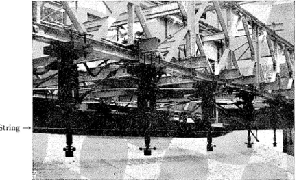
The contribution of gables to the strengths of the complete roofs was demonstrated in two forms. First, the fact that the board-sheathed roofs had strengths not significantly different from the single frames suggests that the direct contribution of the gables was negligible. Secondly, the deflection measurements
made only a short distance along the roof to the conclusioll that the direct con- from the gables were comparable t o tribution of the gables was negligible. those a t the mid-length of the roof, thus 11zdireclly, however, the contribuf.ion of
String
FIG. 5.-Small Elliect oi the Gal~les Shown by Deflections of the Ridge. (Note string stretched from gable peak.)
FIG. 6.-Failure at the Joist Splice.
indicating that the strengthening effect the gables was considerable in that they of the gables did not extend very far into provided the supports for the sheathing the roof (Fig. 5 ) . These two points lead acting as "deep beams."
Joist Splice iITaili7~l.g: 6 and
7).
This suggests that the nailing Another finding lvas the relation be- at the joist splice should be greater than tlveen the through nailing a t the heel that a t the heel joint. Perhaps two or joint and that of the joist splice. Several more additional nails are required a t the building codes, including that of the splice, although it might be expected Federal Housing Administrations and that the sheathing action of the ceilingFIG. 7.-Failure a t the Heel Joint.
the National Building Code of Canada,3 specify the same number of nails in the joist splice as in the heel joint. This re- quirement was met by six of the eight roofs tested, and in every case the joist splice failed before the heel joint (Figs.
Minimum Property Staudards for One and Two Living Units, Federa1 Housing Adminis- tration (FHA No 300), Washington, D. C.
(1958).
would tend to reduce the force on the joist splices.
COSCLVSIONS
In drawing conclusions from the re- sults of these loading tests, i t must be remembered that since only one of each of the eight different roof constructions was tested, the results may not be quantitatively accurate. There are, how-
ever, a number of qualitative conclu- sions that can be drawn for roofs of the type tested:
1. T h e contribution of plywood sheathing to the strength of a complete roof can be substantial, particularly when the roof frames are relatively flesi- ble.
2. The contribution of board sheath- ing to the strength of a complete roof is negligible.
3. The direct co~ltribution of gables
-
to the strength of a complete roof is small.4. The nailing a t the joist splice of a roof frame should he greater than that a t the heel joint for balanced strength in roof design.
Since the strengths determined from the single frames appear to be represen- tative of many complete board-sheathed roofs and since it can he assumed that many roofs in Canada have board sheathing, it may be concluded that the
snow loads they experience are often less than the design snow loads because of wind action, melting due to heat loss, or snow removal b y the owner. This con- clusion serves to reemphasize the im- portance that is already attached to the survey by the Division of Building Re- search of actual snow loacls on roofs, the results of which will be published as soon as sufficient statistically satisfactory in- formation has been assembled and as- sessed.
The authors ~vish to espress their thanks to all those whose time and edort contributed to the successful completion of tliis project. Grateful ack~zowledg- ment is made to R. F. Legget, Director of the Division of Building Research, with whose permission this paper is published, for his encouragement throughout the project.
(1) Synlposiunl on Full-Scale Tests on House cent Failnrcs Point Out Importance of Snow Structures, /lST~lf STP 1'0. 210, .-In]. Soc. Loads on Roofs," Naliorzal Builder, Vol.
Testing Mats. (1957). V I I I , No. 5, May, 19.59, p. 18.
(2) .A. T . Hansen, "1,ightneigh~ Trusses Bear (4
~ f , ,
R, schlieverLv.
G, Plenes, I[-% U p Better Than Conventional Roofs,"Naliorzal Bliilder, Val. VIII, S o . 11, Nov., New Canadian Structural Test Installa-
19.59, pp. 38-10, 51. tion," Er~gilteering Jor~rizc~l, Vol. 44, No. 1, (3) 1-1. J. Thorl~urn and W. R Schricver, "Re- Jan., 1961, pp. 35-41.