HAL Id: hal-01141210
https://hal.archives-ouvertes.fr/hal-01141210
Submitted on 10 Apr 2015
HAL is a multi-disciplinary open access
archive for the deposit and dissemination of
sci-entific research documents, whether they are
pub-lished or not. The documents may come from
teaching and research institutions in France or
abroad, or from public or private research centers.
L’archive ouverte pluridisciplinaire HAL, est
destinée au dépôt et à la diffusion de documents
scientifiques de niveau recherche, publiés ou non,
émanant des établissements d’enseignement et de
recherche français ou étrangers, des laboratoires
publics ou privés.
GPScan.VI: A general-purpose LabVIEW program for
scanning imaging or any application requiring
synchronous analog voltage generation and data
acquisition
Patrick Ferrand
To cite this version:
Patrick Ferrand. GPScan.VI: A general-purpose LabVIEW program for scanning imaging or any
application requiring synchronous analog voltage generation and data acquisition. Computer Physics
Communications, Elsevier, 2015, 192, pp.342. �10.1016/j.cpc.2015.03.010�. �hal-01141210�
GPScan.VI: A general-purpose LabVIEW program for scanning imaging
or any application requiring synchronous analog voltage generation and
data acquisition
Patrick Ferrand
Aix-Marseille Universit´e, CNRS, Centrale Marseille, Institut Fresnel, UMR 7249, Marseille, France
Abstract
A large number of measurement techniques involve the scanning of a probe, while a physical quantity is measured. This is for instance the case for all scanning imaging methods. Data acquisition therefore requires high acquisition rates, together with an accurate synchronization between the probe control and the measurement. The GPScan.VI program is a general purpose LabVIEW program for the control of National Instruments high-speed data acquisition boards, allowing to design scanning imaging systems. Analog output voltages are used to drive a two-dimensional scanning device, while acquisition of analog voltages and TTL pulse counting are run in parallel. Acquisition of megapixel images with pixel dwell times down to the microsecond can be reached with negligible I/O transfer time. The design can be generalized to any situation requiring high speed synchronous generation and acquisition.
Keywords: scanning imaging, high-speed data acquisition, analog output, synchronization, LabVIEW, NI-DAQmx
PACS: 07.05.Dz, 07.05.Hd, 07.79.-v
Program summary
Program Title: GPScan.VI Journal Reference:
Catalogue identifier: AEWG v1 0
Program summary URL: http://cpc.cs.qub.ac.uk/summaries/AEWG v1 0.html Program obtained from: CPC Program Library, Queens University, Belfast, N. Ireland Licensing provisions: Standard CPC licence, http://cpc.cs.qub.ac.uk/licence/licence.html Programming language: LabVIEW (http://www.ni.com/labview/)
Computer: Any machine running LabVIEW 2010 or higher Operating system: Windows XP or higher, OS X
RAM: 5 Mbytes
Supplementary material:
Keywords: scanning imaging, high-speed data acquisition, analog output, analog input, pulse counting, synchroniza-tion, LabVIEW, NI-DAQmx.
Classification: 20
External routines/libraries:
Nature of problem: A large number of measurement techniques involve the scanning of a probe, while a physical quantity is measured. This is for instance the case for all scanning imaging methods. Data acquisition therefore requires high acquisition rates, together with an accurate synchronization between the probe control and the mea-surement.
Solution method: The GPScan.VI program allows to set up National Instruments multifunction acquisition boards,
so that analog output voltage series (used to drive the scanner / probe) are generated, while analog input and counter acquisitions are run synchronously.
Restrictions: Requires National Instruments high-speed multifunction boards, such as X Series or S Series, with at least two analog outputs, and a compatible NI-DAQmx driver installed. The program has been tested on X series boards, with LabVIEW 2011, under Windows 7.
Running time: Real time data acquisition. Scan rates, up to several millions of samples per second, depend on the specification of the board and may be limited by the response of the physical system used to perform the scanning.
1. Introduction
A large number of microscopy techniques, including atomic force microscopy, electron microscopy, con-focal and nonlinear optical microscopy, rely on a scanning scheme. In this operating mode, a probe (tip, electron beam, light spot, etc.) is scanned over an object, while a physical quantity is measured, allowing subsequently to build a digital image of this object. Technically, because this acquisition scheme is sequen-tial and thus intrinsically slow, it requires high acquisition rates, together with an accurate synchronization between the probe control and the measurement. Such control and acquisition devices are available for a while on the market and operate in many commercial scanning imaging systems. In addition, several implementation of such devices for research instruments have been described in the past [1–5]. However, the proposed solutions are complete softwares that are often very specific, may appear complicated to the novice programmer because optimized for versatility, or may be based on devices and/or drivers that are now obsolete. As a consequence, adapting such software to an existing experimental bench remains a challenge for many research labs.
In this article, I describe the GPScan.VI program that allows to configure and use National Instruments (NI) multifunction acquisition boards for this purpose. I focus on providing the technical details of the necessary building blocks in a comprehensive way, and on detailing the critical issues of device configuration, triggering and acquisition rate. The program is built into modular blocks, so that basic tasks such as initializing, measuring and releasing the devices are easy to adapt to any user needs.
2. Program overview 2.1. Requirements
The program GPScan.VI is written in LabVIEW using DAQmx functions, and exploits the features of NI all-in-one high-speed multifunction acquisition boards. It requires the presence of two analog out-put (AO) channels that are exploited for a high-speed (up to several millions of samples per second) and device-independent control of the two-dimensional scanning, since most scanning devices (piezo scanners, galvanometric mirrors, etc.) can be driven by analog voltages. Data acquisition can involve several analog input (AI) channels and/or counters in parallel. AI channels suit for most detectors and sensors, which output voltages, while counters can exploit specific detectors that deliver TTL pulses, such as single photon counting modules.
In the NI product portfolio, suitable acquisition devices will be found among the X [6] or the S [7] series multifunction data acquisition boards. The choice of device [8] will be dictated by the required acquisition rate, internal computer bus (USB, PCIe, PXI or PCI), and available budget.
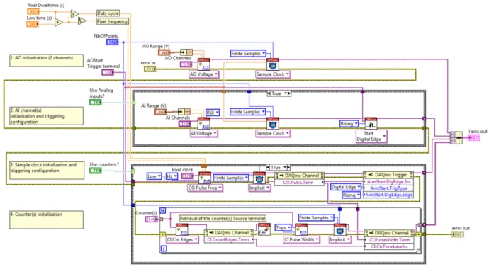
2.2. Subprograms
The tasks corresponding to synchronous scanning and image acquisition are first configured using the Init.VI program, which is depicted in Fig. 1, where the total number of points of the image, together with the pixel dwell time are set. The AO (2 channels) and AI (user defined number of channels) tasks are configured to deliver and measure, respectively, voltages series at the appropriate pixel rate. The counter acquisition is performed using the so-called pulse duration mode in a roundabout way: this measurement mode was indeed originally designed in NI-DAQmx to measure the duration of unknown pulses in terms
Figure 1: Block diagram of Init.VI.
of number of ticks of a reference clock [9]; here the unknown pulses are replaced by a known pulse train generated by one counter (called pixel clock), while the sample clock is replaced by the TTL pulses coming from the detector. In this way, the “pulse duration” values that are returned are actually the number of TTL pulses measured at each pixel coordinate. Finally, in order to ensure a perfect synchronization, AI, pixel clock generation and counters tasks are configured to start at the rising digital edge signal of the AO start trigger terminal.
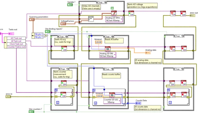
The scanning of an entire frame is performed according to the Scan.VI program, depicted in Fig. 2. First, counter acquisition, pixel clock generation, and AI acquisition are armed, meaning that they are waiting for the triggering signal. Then, based on the scanning parameters (number of pixels in each dimension, scanning amplitude) and voltage factors (which associate a voltage value to a desired scanning amplitude), the values of the AO series corresponding to a 2D raster scan are computed by RasterScanXY.VI (see Fig. A.6) and written on the device. When ready, the AO generation starts, together with the trigged data acquisitions. Then, the complete series of AI and counter measurements are transferred to the computer, when available. Iterative image acquisition is performed by means of a while loop. In this case, AO series are updated to the board only if the scanning amplitudes have changed since the last iteration. Note that although this does not appear on the program, data transfers involve internal buffers and are bidirectional so that AO generation and data acquisition partially overlap in time. Finally, the Close.VI, depicted in Fig. 3 clears all tasks, and releases all the device resources reserved by the tasks.
2.3. Main program
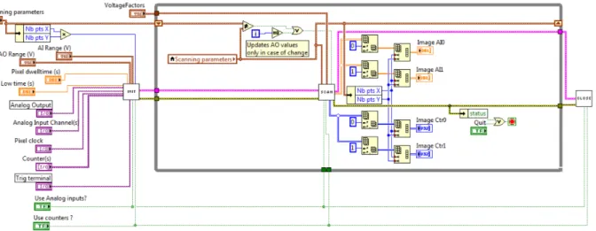
The program GPMain.VI as depicted in Fig. 4 is a basic example of complete scanning and acquisition program, in the case of two AI channels and two counting channels, that illustrates how to manipulate the data series so that they can be displayed as digital images.
Figure 2: Block diagram of Scan.VI. Block diagram of RasterScanXY.VI is given in Fig. A.6.
3. How to use the program
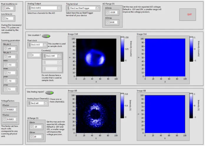
The front panel of the program GPScan.VI is depicted in Fig. 5. The left frame contains the scanning settings, including pixel duration, scanning range, and voltage factors, that allow to adjust the scaling be-tween the scanning physical units and the control voltages. The top panel is used to set the two AO channels, together with the terminal which is used to trig every frame scanning. The middle frame corresponds to the two counter channels, whose parameters are taken into account only if the front panel button “Use counters” is activated. Similarly, the bottom frame deals with AI acquisition and display, when “Use analog inputs” is on.
The block diagram of GPScan.VI, as shown in Fig. 4, corresponds to the case of two AI channels and two counter channels. The first AI channel is extracted by selecting the first row (i.e., of index 0) of the 2D analog data array that is output by GPScan.VI, the second AI channels corresponds to row of index 1, etc. Counter channels data are extracted in the same way from the 2D count data array. Adapting the number of AI and/or counter channels can therefore be done easily by deleting or by duplicating the desired pieces of diagram, with the appropriate index number.
4. Acquisition rate
The program GPScan.VI can typically operate acquisition of megapixel images with pixel dwell times down to the microsecond, the ultimate value of which being dictated by the specifications of the up-date/acquisition rate of the NI device in use. The 16-bit analog to digital converters allow a precision for the AO generation of AI acquisition that is usually high enough to cover all usual experimental needs. GPScan.VI has been used as core program of advanced scanning microscopy softwares [10–14]. The screen capture presented in Fig. 5, has been taken when GPScan.VI operates a multimodal microscopy system detailed in [15], combining here one counter channel and one AI channel. The working parameters used here
Figure 3: Block diagram of Close.VI.
Figure 4: Block diagram of the main program GPScan.VI. In this example, images are acquired in parallel on two AI channels and two counting channels.
correspond to a relatively fast image acquisition (1 fps), with a reduced scanning field definition (15×15 µm2),
providing a sufficient signal to noise ratio and fast response for an efficient focus optimization, for instance. In practice, the acquisition speed depends strongly on the scanning device. Standard galvanometric mirrors usually possess a low inertia so they can routinely operate in a raster scanning mode with dwell times down to tens of microseconds [16], with a possible delay which may induce an artificial shift of the reconstructed image and flyback artifact [1; 10]. Piezo scanning stages, unless specifically designed for speed, work in the millisecond range [11].
Another factor limiting speed is the required signal to noise ratio. This issue could be critical when using photon counting modules. Because of their specific design, these devices are often limited to count rates of a few millions of counts per seconds, i.e., a few counts per microseconds. In these conditions, scanning with pixel dwell times below 10 µs is redhibitory in terms of signal to noise ratio.
Finally, when the application requires a high frame rate, a legitimate concern is the time that is needed to transfer (i) the scanning parameters from the computer to the board, (ii) the measured signal to the computer. This time, which I refer to as “I/O data transfer time”, has to be considered as an incompressible extra delay, in addition to the duration of the measurement itself. It has been measured on NI-USB-6353 device connected to a 3 GHz-CPU laptop (USB2 port) for various scanning conditions and typical values are given in Tab. 1. Predictably, this I/O transfer time is mostly dependent on the amount of data to transfer, i.e., on the total number of pixels, irrespectively of the pixel dwell time. Remarkably, it remains usually small compare to the measurement time, even when AO series are updated from one frame to the next. In
Figure 5: Front panel of the main program GPScan.VI when operating. In this example, images are acquired in parallel on one counting channel and one AI channel. Note that the difference between the two obtained images is due to the different signals acquired by the two channels, namely two-photon fluorescence and coherent anti-Stokes Raman scattering, respectively [15]. Image field of view is 15 × 15 µm2.
usual conditions of imaging, which involve a large number of pixels, one could reasonably consider that the I/O data transfer time is negligible compare to the measurement itself.
Table 1: Measured value of the I/O transfer time (in addition to the measurement itself). Although not critical, dwell time and low time were set to 10 µs and 1 µs, respectively. Measurements were performed on a NI-USB-6353 device.
Number of pixels I/O data transfer time (ms)
w/o AO series update w/ AO series update
10 × 10 138 138
100 × 100 138 142 500 × 500 148 196 1000 × 1000 176 420
5. Conclusion
In conclusion, GPScan.VI can be used as a core program to develop high-speed raster scanning systems using a multifunction device, and can be adapted for any other arbitrary scanning scheme. More generally, it can be used in all kind of instrument which necessitate high speed synchronous signal generation and acquisition.
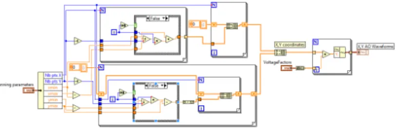
Appendix A. RasterScanXY.VI
The block diagram of RasterScanXY.VI is shown in Fig. A.6.
Figure A.6: Block diagram of RasterScanXY.VI.
Acknowledgments
The author is grateful to H. Rigneault for stimulating discussions. This work has been funded by Agence Nationale de la Recherche under contracts ANR-2010-BLAN-150902, ANR-10-INBS-04-01, ANR-11-INSB-0006, ANR-11-IDEX-0001-02, by Fondation pour la Recherche M´edicale, under contract DBS20131128448 and by Conseil R´egional Provence Alpes Cˆote d’Azur.
References
[1] T. A. Pologruto, B. L. Sabatini, K. Svboda, Scanimage: flexible software for operating laser scanning microscopes, Biomed. Eng. Online 2 (2003) 13.
[2] Q.-T. Nguyen, P. S. Tsai, D. Kleinfeld, Mpscope: A versatile software suite for multiphoton microscopy, J. Neurosc. Meth. 156 (2006) 351–359.
[3] N. A. Hartell, Simple windows-based software for the control of laser scanning confocal microscopes, J. Neurosc. Meth. 162 (2007) 26–31.
[4] A. A. Bettiol, C. Udalagama, F. Watt, A new data acquisition and imaging system for nuclear microscopy based on a field programmable gate array card, Nucl. Instrum. Meth. Phys. Res. B 267 (2009) 2069–2072.
[5] D. J. Kim, Z. Fisk, A labview based template for user created experiment automation, Rev. Sci. Instrum. 83 (12) (2012) 123705.
[6] National Instruments, DAQ X Series user manual, National Instruments, Austin, TX (2012). [7] National Instruments, DAQ S Series user manual, National Instruments, Austin, TX (2009). [8] Accessed 01/06/2015. [link].
URL http://www.ni.com/dataacquisition/
[9] National Instruments, LabVIEW measurements manual, National Instruments, Austin, TX (2003).
[10] P. Ferrand, M. Pianta, A. Kress, A. Aillaud, H. Rigneault, D. Marguet, A versatile dual spot laser scanning confocal microscopy system for advanced fluorescence correlation spectroscopy analysis in living cell, Rev. Sci. Instr. 80 (2009) 083702.
[11] E. Mudry, E. Le Moal, P. Ferrand, P. C. Chaumet, A. Sentenac, Isotropic diffraction-limited focusing using a single objective lens, Phys. Rev. Lett. 105 (2010) 203903.
[12] S. Brustlein, P. Ferrand, N. Walther, S. Brasselet, C. Billaudeau, D. Marguet, H. Rigneault, Optical parametric oscillator-based light source for coherent Raman scattering microscopy: practical overview, J. Biomed. Opt. 16 (2) (2011) 021106.
[13] S. Saint-Jalm, E. R. Andresen, P. Ferrand, A. Bendahmane, A. Mussot, O. Vavincq, G. Bouwmans, A. Kudlinski, H. Rigneault, Fiber based ultra-short pulse delivery for nonlinear imaging using high energy solitons, J. Biomed. Opt. 19 (2014) 086021.
[14] P. Ferrand, P. Gasecka, A. Kress, X. Wang, F.-Z. Bioud, J. Duboisset, S. Brasselet, Ultimate use of two-photon fluorescence microscopy to map orientational behavior of fluorophores, Biophys. J. 106 (2014) 2330.
[15] J. Duboisset, P. Berto, P. Gasecka, F.-Z. Bioud, P. Ferrand, H. Rigneault, S. Brasselet, Molecular orientational order probed by coherent anti-stokes raman scattering (cars) and stimulated raman scattering (srs) microscopy: A spectral comparative study, J. Phys. Chem. B 119 (2015) 3242.
[16] L. Beiser, Unified optical scanning technology, Wiley, Hoboken, 2003.