REVIEW
Containment versus impingement: finding a compromise
for cup placement in total hip arthroplasty
K.-H. Widmer
Published online: 28 July 2007 # Springer-Verlag 2007
Abstract Recommendations for cup containment and impingement may provide conflicting directions for com-ponent orientation in total hip arthroplasty. For optimal containment, the cup is positioned with respect to the acetabular bone, resulting in coincidence of the rim of the cup and the acetabulum. This results in good coverage and symmetric load transfer, leading to good long-term stability, but occasionally necessitates more abduction of the cup than that recommended by the safe zone. On the other hand, placement of the cup for an optimal range of motion would lead to only partial containment, with a higher risk of component loosening and revision. The most effective compromise is to use a prosthesis that has a large safe zone, realised by a high head-to-neck ratio, and orienting the cup such that a good containment is achieved and the safe zone is respected. Computer navigation or smart aiming devices may help to find the best relative orientation.
Introduction
Besides pain relief, patients expect hip replacement to restore good joint function with successful long-term fixation of the components. There is no doubt that a high standard in total hip replacement has been achieved nowadays and nearly one million patients are provided with new perspectives in their lives from this development
world-wide each year. But what is necessary to realise secure component fixation and orientation, especially in the non-cemented cup?
Cementless pressfit acetabular cups have been widely accepted and became the standard in total hip arthroplasty. The fixation of these cups in acetabular bone and their load transfer has been studied by several groups [1]. There is also a trend to prefer hemispheric cups that are ideally suited for pressfit techniques and to preserve as much acetabular bone as possible. These cups distribute com-pressive fixation forces to the periphery near the equator of the acetabulum, where they generate friction forces, which hold the cup in place [2–4]. Such a load pattern is close to that in a natural hip joint. Therefore, it can be hypothesised that this load transfer guarantees the best long-term fixation of an acetabular cup, as it does not alter the normal load transfer of a natural hip joint [5].
Furthermore, the cups must be implanted in such a way that the best containment is achieved, i.e. the rim of the acetabular bone and the rim of the socket should coincide as closely as possible. This may lead to a higher cup abduction that may be different from cup orientations that are recommended with respect to a good range of motion. In addition, it may generate prosthetic impingement, leading to additional problems, such as subluxation, dislocation and rim damage in hard-on-hard bearings. The question arises on how this conflict can be resolved. This paper addresses this conflict and tries to give possible solutions.
Cup containment
There are numerous recommendations on how to orient the prosthetic cup with respect to the rim of the acetabular bone. These cups are evaluated as fully contained and less
DOI 10.1007/s00264-007-0429-3
In the preparation of this article, no funding was received in any form whatever. The content of this manuscript is not linked to any product that is commercially available and there are no conflicts of interest directly or indirectly relevant to the contents of this manuscript. K.-H. Widmer (*)
Department for Orthopedic Surgery and Traumatology, Kantonsspital Schaffhausen,
8208 Schaffhausen, Switzerland e-mail: [email protected]
radiolucencies were seen in the interface of these cups [6]. A more horizontal orientation leads to a partial containment only and a higher rate of radiolucencies is seen thereafter. Furthermore, the lack of containment was correlated with a higher rate of loosening in the long term [7].
Good containment of the cup is necessary for a reliable pressfit. The pressfit technique requires that contained parts on the outer surface of the cup be opposed in order to build up opposing forces in the implant–bone interface that compress the prosthetic socket. Such compressing forces are provided at those parts of the acetabulum that are supported by the iliac, pubic and ischial bones [1] (Fig.1). The cup should be supported by the cortical bone on its outer surface, i.e. the rim of the cup should not sink into the reamed acetabulum, otherwise, the cup is supported by cancellous bone only. Cancellous support alone weakens primary stability and will disturb osseointegration and, finally, completely prevent it (Fig.2). So, cortical contact of the outer surface of the cup is an essential feature of pressfit implantation.
Impingement
Impingement may occur as component-to-component im-pingement, bone-to-bone impingement or component-to-bone impingement. If any scar tissue is formed around the neck, this tissue can also interfere with the prosthesis neck, leading to additional soft tissue impingement. While bone-to-bone impingement is addressed by the offset of the prosthesis, component-to-component impingement is high-ly dependent on the design parameters and component orientation [8,9].
There are numerous papers covering the recommenda-tions on how the components should be positioned in total hip arthroplasty. Lewinnek introduced the safe zone concept in 1978 [10]. He derived his recommendations from clinical findings: cup orientation from 5° to 25° of anteversion and 30° to 50° of abduction showed a lower rate of dislocation. Nothing is said about the stem orientation. Apparently, the cup and neck should be oriented relative to each other, accordingly, in order to prevent cup-to-neck impingement. This is expressed by the so-called “combined version” for the cup and stem.
Ranawat recommends different combined versions for men and women [11], while computer simulation with three-dimensional models revealed that the size of the safe zone is optimised when the “intended range of motion” concept is introduced. This concept tells the surgeon which component orientation he/she should adhere to when a predefined range of motion should be reached by the patient [12]. There is a linear correlation between cup anteversion and stem antetorsion [12], and also between cup abduction and the neck-to-shaft angle of straight stems [8]. The optimal range for the neck-to-shaft angle is between 125° and 130°. These stems allow the lowest cup abductions, which is beneficial for a small edge loading and for a reduced risk of dislocation. In addition, it is close to the CCD angles found in the normal femur [13–15].
The amazing thing about component orientation in total hip arthroplasty is that there is no need to stick to an absolute orientation when implanting the first component, but, as soon as the position of this first component is fixed, the second component has to be positioned in a compliant orientation to the first component. Hence, the relative positioning of the components is more important than the absolute positioning with regard to bony landmarks.
This goal is best achieved when the second component is intentionally oriented relative to the first component, i.e. the surgeon may follow the“stem first” concept, where the cup is positioned relative to the stem after the trial stem has been implanted [12]. As a matter of course, the orientation of the cup relative to the stem has to be known for each prosthesis system when this concept is applied. Alterna-tively, one may introduce modularity in cups or stems to accommodate for relative component positioning.
The most efficient way to reduce the risk of impinge-ment is increasing the head-to-neck ratio by either increasing the head size or by reducing the neck diameter
Fig. 1 Most of the load is transferred at these three dis-tinct areas, where the acetabular bone is supported by the iliac, pubic and ischial bone (three-spot support, left acetabulum)
Fig. 2 Seating the cup beyond the cortical rim of the acetabulum will put its osseointegration at risk. Cortical rim contact of the cup is necessary for primary stability and secure osseointegration
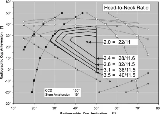
or both. The head-to-neck ratio should at least be 2 or more, i.e. the diameter of the head should be double the neck diameter. Increasing the head-to-neck ratio will increase the size of the safe zone (Fig. 3). As one would expect, said changes in head size have a greater influence on the safe zone in smaller heads (e.g. 22–26 mm) than in larger heads (e.g. 38–42 mm).
Additionally, the risk of dislocation is reduced, not only by preventing impingement, but also by increasing the distance that is required to lift the head out of the cup. Soft-tissue tension increases when the prosthesis head is lifted and this tension counteracts further dislocation. Fortunately, larger head sizes are a valuable option nowadays, in combination with cross-linked polyethylene and hard-on-hard bearings (e.g. ceramic-on-ceramic and metal-on-metal), which provide enhanced wear resistance, without the need for excessive reaming of the acetabulum.
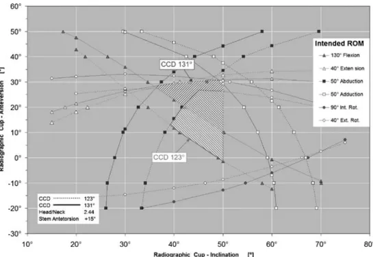
The simulations for the range of motion suggest orienting the cup to be less inclined and more anteverted in prosthesis systems with a straight stem [8]. Combining low abduction and low anteversion is not recommended, as it leads to impingement during flexion. Moreover, one should not stick to fixed absolute values defining the orientation of the components, but one should position the components with regard to the specific safe zones that can be determined for each prosthesis system (Fig. 4). Obvi-ously, there is a strong interrelationship between the four angles defining the orientation of both components. Neck-shaft angle and antetorsion of the stem greatly determine how the cup should be positioned. When offset stems are
used with a reduced neck-shaft angle, the anteversion of the cup should be reduced too [8]. Neck-shaft angles greater than 135° lead to a dramatic reduction in the range of motion and should be avoided.
Discussion
The orientation of the natural acetabular opening in the human pelvis can vary from anteversion to retroversion, and its abduction can vary from lower to higher degrees too. Furthermore, the cavity tends to be shallow in cases of dysplasia and rather deep in cases with protrusion of the femoral head. Hence, orienting the prosthetic cup with regard to the acetabular rim alone may result in a wide spectrum of cup orientations. However, in each case, the improved containment of the cup is expected to lead to greater long-term stability of the prosthesis. One may even accept extreme but compliant positions of the components in order to obtain good component fixation and long-term stability, as long as the morphology of the proximal femur and the pelvis allows the stem and the cup to be placed in complementary orientations.
The situation becomes more challenging during prepa-ration of the acetabulum or the femur, when it becomes clear that it is infeasible to orient the components in complementary positions. This happens quite frequently, because, in general, the orientation of the neck is not reflected by a corresponding orientation of the acetabulum and, moreover, the abduction of the acetabulum is higher
Fig. 3 The safe zone for cup orientation increases with in-creased head-to-neck ratio, pro-viding more room for error
than the recommended abduction for the prosthetic socket. So, it is inescapable to find a compromise between the containment of the cup and the risk of impingement. If ever in doubt, good containment is preferable in order to achieve a good fixation of both components, because long-term fixation of the components is an indispensable requirement for a successful total hip arthroplasty. The diagrams showing the safe zones may help to find a good compromise. For example, they indicate that a small anteversion or even retroversion of the acetabulum can be best met with a stem having a low neck-to-shaft angle, as these stems complement the placement of the acetabular cups in less anteversion.
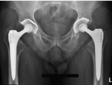
In cases with underdeveloped acetabular bone stock, like in a case of congenital dysplastic hip, one should aim for the optimal relative component fixation (Fig. 5). Here, reaming the acetabular bone according to the basic require-ments of good cup fixation at the correct site helps to restore the biomechanics of the hip. Sometimes, it is additionally helpful to use stems that allow the prosthetic neck to be placed in a wide range of rotational positions independent of the original morphology of the proximal femur.
It may also be suggested that the relative orientation of the outer surface of the cup and the articulating surface of the liner should be decoupled to allow differences in orientation. With such a modular cup, the outer surface can be oriented in full accordance with the needs of optimal cup fixation and containment, whereas the inner articulating surface can be oriented according to the recommendation for a maximised safe zone providing the greatest range of motion, together with a given stem.
What is the role of computer-assisted surgery in total hip arthroplasty, in particular, computer navigation? Above all, computer navigation software should have a built-in database that illustrates the safe zone for each prosthesis system considering its specific design and implantation parameters. Based on this built-in knowledge, such a navi-gation system converts from a simple three-dimensional measuring system to a real navigation tool that supports the surgeon in finding the best way of component orientation, especially in setting the complementary orien-tation of the cup or the femoral stem when the orienorien-tation
Fig. 5 Secure fixation is achieved by precise reaming of the acetabular bone, even in dysplastic pelvises. Hip biomechanics is restored on the right side after distraction (distance=8.5 cm) Fig. 4 Shape and position of
the safe zone is dependent on the neck-to-shaft angle of the stem
of its mating component has already been set. In following such a procedure, slight misplacement of the first compo-nent does not have any adverse effects, as the navigation system can recompute the best orientation of the second component to restore the relative orientation of both components to the safe zone. In particular, there is no longer any need to stick to fixed, predefined values for the positioning of either component.
There is also a role for smart non-computer-based aiming devices that can be constructed to provide system-specific guidance in ensuring that components are oriented within the safe zone of each implant system. Although such a device may lack the versatility of a real computer-based navigation system, it may provide enough support by solving the task of orienting the components without the need for the time-consuming setup and application of a conventional navigation system. Such an option could be highly attractive for a modular cup or a modular stem.
References
1. Elke R, Marugg S (1992) Transmission of force to the trabecular structures of the proximal end of the femur (in German). Orthopäde 21:51–56
2. Laursen JO, Petersen B, Mossing NB (1998) The Richards Series 2 total hip prosthesis: a 13-year study and radiographic evaluation. Orthopedics 21:277–282
3. Lewinnek GE, Lewis JL, Tarr R, Compere CL, Zimmermann JR (1978) Dislocations after total hip-replacement arthroplasties. J Bone Joint Surg Am 60(2):217–220
4. Morscher EW (1992) Current status of acetabular fixation in primary total hip arthroplasty. Clin Orthop Relat Res 274:172–193 5. Massin P, Geais L, Astoin E, Simondi M, Lavaste F (2000) The anatomic basis for the concept of lateralized femoral stems: a frontal plane radiographic study of the proximal femur. J Arthroplasty 15:93–101
6. Noble PC, Alexander JW, Lindahl LJ, Yew DT, Granberry WM, Tullos HS (1988) The anatomic basis of femoral component design. Clin Orthop Relat Res 235:148–165
7. Ranawat CS, Maynard MJ (1991) Modern techniques of cemented total hip arthroplasty. Techniques Orthoped 6:17–25
8. Sarmiento A, Ebramzadeh E, Gogan WJ, McKellop HA (1990) Cup containment and orientation in cemented total hip arthro-plasties. J Bone Joint Surg Br 72:996–1002
9. Schidlo C, Becker C, Jansson V, Refior J (1999) Change in the CCD angle and the femoral anteversion angle by hip prosthesis implantation (in German). Z Orthop Ihre Grenzgeb 137:259–264 10. Shirazi-Adl A, Dammak M, Paiement G (1997) Experimental determination of friction characteristics at the trabecular bone/ porous-coated metal interface in cementless implants. J Biomed Mater Res 27:167–175
11. Widmer K-H, Zurfluh B (2004) Compliant positioning of total hip components for optimal range of motion. J Orthop Res 22:815– 821
12. Widmer K-H, Majewski M (2005) The impact of the CCD-angle on range of motion and cup positioning in total hip arthroplasty. Clin Biomech 20:723–728
13. Widmer K-H, Zurfluh B, Morscher EW (1997) Contact surface and pressure load at implant–bone interface in press-fit cups compared to natural hip joints (in German). Orthopäde 26:181–189 14. Widmer K-H, Zurfluh B, Morscher EW (2002) Load transfer and fixation mode of press-fit acetabular sockets. J Arthroplasty 17:926–935
15. Yoshimine F (2006) The safe-zones for combined cup and neck anteversions that fulfill the essential range of motion and their optimum combination in total hip replacements. J Biomech 39:1315–1323