Electron Capture Dissociation Implementation
Progress in Fourier Transform Ion Cyclotron
Resonance Mass Spectrometry
Yury O. Tsybin,a John P. Quinn,b Oleg Yu Tsybin,c
Christopher
L.
Hendrickson,b,d and Alan G. Marshallb,d
aBiomolecular Mass Spectrometry Laboratory, Ecole Polytechnique Federale de Lausanne, Lausanne, Switzerland bIon Cyclotron Resonance Program, National High Magnetic Field Laboratory, Florida State University, Tallahassee, Florida, USA
CIon Physics Laboratory, State Polytechnical University, St. Petersburg, Russia
dDepartment of Chemistry and Biochemistry, Florida State University, Tallahassee, Florida, USA
Successful electron capture dissociation (ECD) Fourier transform ion cyclotron resonance mass spectrometry (FT-ICR MS) applications to peptide and protein structural analysis have been enabled by constant progress in implementation of improved electron injection techniques. The rate of ECD product ion formation has been increased to match the liquid chromatography and capillary electrophoresis timescales, and ECD has been combined with infrared multipho-ton dissociation in a single experimental configuration to provide simultaneous irradiation, fast switching between the two techniques, and good spatial overlap between ion, photon, and electron beams. Here we begin by describing advantages and disadvantages of the various existing electron injection techniques for ECD in FT-ICR MS. We next compare multiple-pass and single-pass ECD to provide better understanding of ECD efficiency at low and high negative cathode potentials. We introduce compressed hollow electron beam injection to optimize the overlap of ion, photon, and electron beams in the ICR ion trap. Finally, to overcome significant outgassing during operation of a powerful thermal cathode, we intro-duce nonthermal electron emitter-based electron injection. We describe the first results obtained with cold cathode ECD, and demonstrate a general way to obtain low-energy electrons in FT-ICR MS by use of multiple-pass ECD. (JAm Soc Mass Spectrom 2008, 19, 762-771)©2008 American Society for Mass Spectrometry
E
lectron capture dissociation (ECD) in Fourier trans-form ion cyclotron resonance mass spectrometry (FT-ICR MS) is one of the most prominent methods for complete peptide and protein structural characteriza-tion [1-5]. The analytical power of ECD in FT-ICR MS encouraged researchers to develop alternative methods for lower resolution mass spectrometers. As a result, ECD and ion-ion reaction based electron-transfer dissociation (EID) have been implemented and developed into effi-cient tools in linear and Paul radiofrequency ion traps [6-10] as well as in a digital ion trap [11]. ECD/EID implementation in radiofrequency devices that typically constitute the first stage of a hybrid mass spectrometer allows for subsequent high-resolution detection of prod-uct ions with FT-ICR, Orbitrap [12], or time-of-flight (TOF) [13] mass analyzers. Moreover, peptide and protein struc-tural analysis by ECD in high vacuum (FT-ICR MS) and ECD/EID under low vacuum conditions (radiofrequency multipole ion traps) offer complementary approachesAddress reprint requests to Dr.Y.O. Tsybin, Biomolecular Mass Spectrom-etry Laboratory, Ecole Polytechnique Federale de Lausanne, CH-1015, Lausanne, Switzerland. E-mail: [email protected]
differing in ion internal energy. Inparticular, ECD in a high vacuum ICR ion trap offers potential advantages for bottom-up and top-down analyses of peptides and pro-teins, and pursuit of further improvement in ECD effi-ciency is therefore warranted.
ECD efficiency and product ion abundance distribu-tion vary as a funcdistribu-tion of electron injecdistribu-tion condidistribu-tions as well as ion activation and motion in the ICR trap [14-19]. Progress in electron injection in ECD FT-ICR MS [20] has been aimed mainly toward increased ECD reliability, rate, and compatibility with infrared multiphoton dissociation (IRMPD), as shown in Table 1 and summarized here: • Narrow electron beam (directly heated filament),
Table I, top left [I, 21]. Hot filament-based electron injection was originally employed for ECD by Zubarev et al. in 1998 and spawned the first applica-tion of ECD to peptide and protein structural analysis [21]. Despite its ease of implementation and low heating power level, hot filament based ECD was not sufficiently reliable and reproducible, and required a long electron irradiation period (typically seconds) for extensive product ion formation [22,23].
© 2008 American Society for Mass Spectrometry. Published by Elsevier Inc. 1044-0305/08/$32.00
doi:l0.1016/j.jasms.2008.02.007
Published online March 4, 2008 Received December 15, 2007 Revised February 13, 2008 Accepted February 14,2008
• Wide electron beam (dispenser cathode), Table 1, middle left[24]. In 2001, large diameter (up to 10 mm) disk shaped dispenser cathodes were implemented by Zubarev in Denmark and Håkansson in Sweden, for improved reliability of ECD and increase in ECD rate by two orders of magnitude[24]. Combination of ECD with liquid chromatography [25]and capillary electrophoresis[26]thus became possible. Dispenser cathode based ECD was taken as the basis for commer-cialization by all leading FT-ICR MS manufacturers. However, the dispenser cathode exhibited increased heating power level and limited compatibility with conventional on-axis IRMPD.
• Compressed electron beam (dispenser cathode),
Ta-ble 1, bottom left[27]. To provide space for IR laser
injection (both on-axis and angled off-axis) and in-crease electron beam density (flux), a dispenser cath-ode may be mounted remotely from the ICR trap in the magnet fringe field region. However, cathode alignment and increased heating power (to compen-sate for larger cathode diameter required to generate a broad cross-section compressed beam) remained problematic.
• Hollow electron beam (hollow dispenser cathode),
Table 1, top right[28]. Hollow (tubular) electron beam
based ECD became standard on commercial systems (Bruker Daltonics GmbH, Bremen, Germany), allowing combination of ECD and IRMPD in a single experi-mental configuration without beam compression and increased heating power [28]. The success of the hollow beam ECD is mainly due to ion motional trajectories in ICR trap that allow for efficient overlap of precursor ions with both the on-axis IR laser beam and on-axis tubular electron beam. Nevertheless, careful alignment was needed to ensure the overlap of ion, electron and photon beams [16].
The ECD improvement obtained by replacing a narrow electron beam with a wide, large diameter beam with higher electron flux was due mainly to efficient electron trapping in the region of the ICR trap, namely, multiple-pass ECD[15]. In contrast to single-pass ECD, in which electrons pass through the center of the ICR trap only once, electrons trapped between the negative potential of the cathode and the even more negative potential of the ion injection electrodes (e.g., the ion transfer
octo-Table 1. Progress of ECD implementation in FT-ICR MS: (top left) narrow electron beam (directly heated filament), (middle left) wide electron beam (indirectly heated dispenser cathode), (bottom left) compressed electron beam (disk-shaped dispenser cathode), (top right) hollow electron beam (hollow dispenser cathode), (middle right) compressed hollow electron beam (hollow dispenser cathode), (bottom right) ultra-wide “cold” electron beam (non-thermal electron source)
1998: thin electron beam (directly heated filament) 2003: hollow electron beam (hollow dispenser cathode)
Advantages: easy to
implement and handle; low power level
Advantages: simultaneous ECD/IRMPD; high rate
Disadvantages: typically poor overlap of ions and electrons, electron energy control; low rate;
repeatability
Disadvantages: limited overlap of electron, ion and photon beams; thermal activation
2000: wide electron beam (dispenser cathode) 2006: compressed hollow electron beam (large hollow dispenser cathode)
Advantages: better overlap of ions and electrons, energy control; higher electron flux; high rate
Advantages: good (complete) overlap of electron, ion and photon beams; higher electron flux; on-axis geometry; high rate Disadvantages: limited ECD/
IRMPD combination possibility; crosstalk; thermal activation
Disadvantages: high power level required (outgassing); vacuum chamber volume; alignment; thermal activation
2002: compressed electron beam (dispenser cathode) 2006: “cold” ultra-wide electron beam (non-thermal electron emitter)
Advantages: simultaneous ECD/IRMPD; high rate
Advantages: non-thermal activation; fast switch on/off time; decreased outgassing; wider and more uniform electron beams with higher flux; decreased charge build-up; high rate
Disadvantages: decreased electron beam diameter; electron reflection; alignment; thermal activation
Disadvantages: electron energy control; electron source lifetime
pole) make multiple passes through the ICR trap[15]. As a result, the number of electrons increases with time leading to rapid ECD. Alternatively, nested ICR trap geometry [1] and gas-assisted plasma ECD [29] have been employed to optimize ion-electron interaction through electron trapping/repelling in the ICR trap.
The more extensive fragmentation of combined ECD/IRMPD [14, 30, 31]triggered alternative IR laser beam injection configurations, including: off-axis an-gled IRMPD with an additional lens to focus the ICR laser beam (ThermoFischer Scientific, Bremen, Ger-many); reflection of the IR beam from a movable mirror mounted in the ion transfer line, allowing for IR beam injection from the trap end opposite to that for electron beam injection[32]; and off-axis injection of an IR laser beam into the ICR trap with subsequent reflection of the angled IR beam through the center of the trap by a mirror installed inside the trap [19, 33].
The major drawbacks of present electron injection methods (seeTable 1) are extensive outgassing due to thermal heating of the emitter itself and surrounding parts, including the ICR trap, producing higher pres-sure in the ICR trap and insufficient overlap of the ions, electrons, and photons required for efficient combina-tion of ECD with ion activacombina-tion/dissociacombina-tion by IR laser irradiation. Here, we present an overview of ECD implementation configurations since the first develop-ment of ECD a decade ago, and demonstrate new methods of electron injection into the ICR trap. The new ECD configurations are based on mechanistic analysis of both single-pass and multiple-pass ECD.
Methods
Sample Preparation
The neuropeptide, Substance P, and formic acid were purchased from Sigma (St. Louis, MO). Acetonitrile and
water (HPLC grade) were purchased from J. T. Baker (Philipsburg, NJ). For electrospray, aqueous stock solu-tions were diluted to a concentration of 1–10 M in 50/50 vol/vol acetonitrile:water with 0.1% (vol/vol) formic acid.
Fourier Transform Ion Cyclotron Resonance
Mass Spectrometry
Mass analysis was performed with a custom-built 9.4 T ESI-Q-FT-ICR mass spectrometer [27]. Microelectros-pray flow rate was ⬃300 nL/min. After 0.1–5 s accu-mulation in an external octopole ion trap (4.8 mm i.d., 15 cm long, 300 Vp-p at 1.5 MHz) and precursor ion
selection in an external quadrupole mass filter ions were transported through a radiofrequency octopole ion guide (4.8 mm i.d., 160 cm long, 225 Vp-pat 1.5 MHz)
into an open-ended cylindrical ICR trap (94 mm i.d., 300 mm long with 100 mm long excitation/detection and segmented cylindrical end cap electrodes). Gated ion trapping was conducted without cooling gas. Tandem mass spectrometry (MS/MS) was performed with each of three electron injection configurations: conventional dispenser cathode, hollow cathode in the magnetic fringe field, and a cold electron emitter. Single-pass and multiple-pass electron injection were employed[15, 20]. The D.C. offset potential of the transfer octopole served as an electron mirror to control electron reflection (see
Figure 1). The transfer octopole D.C. potential was⫺60
V during ion injection into the ICR trap and pulsed to a user-defined value (⫾100 V) during ECD. Multiple-pass ECD occurs if the octopole D.C. potential is more negative than the cathode potential. Product ions were frequency-sweep excited before broadband detection. The time-domain transient signal was baseline cor-rected, Hanning apodized, zero-filled, and Fourier transformed to produce a magnitude-mode frequency
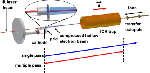
cathode grid transfer octopole ICR trap IR laser beam B ions compressed hollow electron beam single pass multiple pass cathode grid transfer octopole ICR trap IR laser beam B ions compressed hollow electron beam single pass multiple pass
Figure 1. Experimental configuration for ECD FT-ICR MS with a compressed hollow electron beam. A hollow electron emitter is located in the magnet fringe field. An IR laser beam may be introduced into the ICR trap on-axis. Ions and electrons/photons are injected into the ICR trap from opposite ends of the ICR trap. Depending on the applied potentials, electrons can pass through the ICR trap once (single-pass regime) or multiple times (multiple-pass regime).
spectrum that was converted to an m/z spectrum by the quadrupolar approximation. Data acquisition was per-formed by use of a Predator data station and data analysis with MIDAS 2.7 software [34]. ECD efficiency was calculated following the method described by McFarland et al. [15] with charge state correction for multiply charged product ions.
ECD with a Dispenser Cathode
Electrons were injected into the ICR trap from the opposite end of the trap for ion injection, followed by an electron clean-up event (100 ms)[15]. In a typical ECD configuration, a 10 mm diameter electron beam was produced by a disk-shaped heated dispenser cathode located in the magnet fringe field region. Due to com-pression of the electron beam with increasing magnetic field, the electron beam diameter inside the ICR trap was ⬃3 mm. The cathode potential during electron injection was⫺5 V and held at ⫹10 V otherwise.
ECD with a Hollow Electron Emitter in the
Magnet Fringe Field
Electrons were generated by a custom-built hollow electron emitter (hollow dispenser cathode) with 4.7 mm i.d. and 15.2 mm o.d. (HeatWave, Watsonville, CA). The electron emitter was installed on-axis in the magnet fringe field region with magnetic induction of ⬃1.4 T at a distance of 65 cm from the ICR trap center
(see Figure 1). The electron emitter was installed on a
vacuum-sealed moveable probe that allowed for transla-tional and radial adjustment of cathode position. The increase in magnetic field magnitude, proceeding from the cathode to the ICR trap, compresses the electron beam into a beam with an i.d. of⬃0.1 mm and o.d. of ⬃6 mm inside the ICR trap. Assuming negligible variation of magnetic field over an electron cycloidal motion step (adiabatically inhomogeneous magnetic field), electron beam compres-sion is governed by the conservation of magnetic flux in the perpendicular cross-sectional radius, R (BR2⫽ const.),
seeTable 1. The o.d. of the electron emitter was chosen to
provide a wide on-axis electron beam in the ICR trap, whereas the inner electron emitter diameter was chosen to be large enough for on-axis IR laser beam injection. The power required for efficient electron generation from the present electron source was⬃45 W (5 V at 9 A). ECD FT-ICR MS experiments with a hollow cathode in the magnet fringe field were performed with a Predator data acquisition system, for both single-pass and multiple-pass electron injection.
ECD with a Cold Electron Emitter
Recent progress in nanotechnology has led to commer-cially available cold cathodes for efficient electron gen-eration in various applications. Field emission cold triode cathode ATC-CR (field emission film active area
5 mm ⫻ 10 mm) and custom-built cathodes (field emission film active area diameter 20 mm) were ob-tained from Xintek Inc. (Research Triangle Park, NC) and modified for operation at high magnetic field. Electrons are produced by field emission from carbon nanotubes arranged on the conducting surface (cath-ode). A strong electric field is created by applying high voltage (1–2 kV) between the cathode and the extraction grid electrode (gate). The gate electrode is located⬃0.1 mm from the tips of the carbon nanotubes. The triode electron source configuration was employed in the current work with an additional grid (anode) placed between the gate electrode (gate–anode distance ⬃5 mm) and the ICR trap.
We suggest the use of the cold electron emitters for production of low-energy electrons required for ECD
(Table 1, bottom right). In the present configuration,
first a commercial (active area 5 mm⫻ 10 mm) and then a custom-built 20 mm o.d. disk-shaped cathode were placed 50 cm axially from the ICR trap center in the magnet fringe field (typical location for mounting a dispenser cathode for ECD experiments on this FT-ICR MS instrument) and operated at low potential (⫾50 V) with the gate electrode pulsed to high positive potential (1–2 kV) during electron emission and kept at the cathode potential otherwise. The additional grid elec-trode (anode) shields ions in ICR trap from the high potential of the gate electrode and is operated at the same potential as for typical ECD conditions, namely ⫹5 V during ECD and ⫺200 V otherwise. Fast switch-ing of high voltages on the gate electrode was accom-plished with a high voltage pulse supplier (model AMS-10B2-LCPvS, manufactured by Matsusada Preci-sion Inc., Kyoto, Japan). The rise time of the high voltage pulse was ⬃300 us (from 0 V to 2 kV). ECD FT-ICR MS experiments with the cold cathode were controlled by a Predator data acquisition system for both single-pass and multiple-pass electron injection.
Results and Discussion
Multiple-Pass Versus Single-Pass ECD
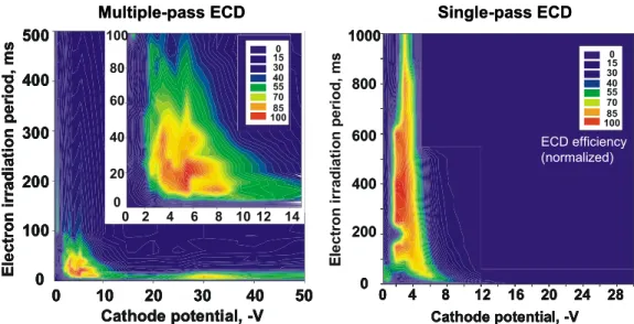
Single-pass and multiple-pass ECD are shown inFigure 2. Multiple-pass electron injection was achieved by bias-ing the transfer octopole to⫺50 V during ECD, whereas the transfer octopole potential was⫹50 V during single-pass ECD. Overall, ECD efficiency correlates well with the reported data for typical ECD parameters (⫺5 V cathode potential and 10 ms optimum irradiation pe-riod for multiple-pass operation)[15]. However, for the same cathode potential, ⫺(0–5) V and ECD efficiency, single-pass electron injection requires⬃10 times longer irradiation period than multiple-pass electron injection, thereby confirming previously reported much lower single-pass ECD efficiency for same (short) electron irradiation period as for multiple-pass. The range of cathode potentials at which ECD efficiency is acceptable for peptide and protein structure analysis is wider for
multiple-pass than single-pass ECD. Single-pass ECD efficiency is maximal at ⬃⫺3 V cathode potential and electron irradiation period of⬃300–400 ms, compared with ⬃⫺5 V and 15–20 ms for multiple-pass ECD
(Figure 2, left, inset). ECD efficiency drops off faster
with increased cathode potential for single-pass than for multiple-pass and is negligible at ⬃⫺8 V cathode potential for single-pass. Multiple-pass electron irradi-ation for longer than 100 ms presumably induces sec-ondary fragmentation [29], thereby reducing the effi-ciency of primary product ion formation. More than tenfold longer electron irradiation (1 s and longer) may be required in single-pass ECD, due to lower probabil-ity and cross section of ion-electron interaction (lower number of injected (no electron trapping) electrons and their higher average energy).
For comparison of single-pass and multiple-pass ECD efficiency, both radical and prime product ions should be taken into account. Interestingly, radical
c-type ions typically observed for c4, c5, and c6 ions in
multiple-pass ECD of Substance P[14]are missing in its single-pass ECD. Figure 3 demonstrates the depen-dence of c5 ion radical/prime ratio as a function of
octopole potential, affording a clear transition between single-pass and multiple-pass operation. Increasing the cathode potential from ⫺5 V to ⫺2 V shifted the threshold value for c·/c= transformation toward a slightly more positive repelling (octopole) potential. Based upon comparison of ECD with and without IR activation[14], the presence of radical c-ions in multiple-pass ECD suggests interaction with lower-energy elec-trons (⬍1 eV) than for single-pass ECD. What then is the mechanism of electron energy reduction in multiple-pass electron injection? The number of secondary electrons in multiple-pass ECD should be negligible. The primary
electrons are trapped in the potential well between the negative cathode potential and even more negative D.C. offset on the transfer octopole without direct interaction with metal electrodes (except the positively biased acceleration grid). We suggest that multiple reflections of electrons in the magnet fringe field result in conver-sion of electron parallel (to the mass spectrometer axis) velocity component into its perpendicular component. However, because the electron total energy is con-served, electrons are necessarily slowed on-axis; they cannot return to the cathode and relax axially toward the center of the ICR trap. As a result, in multiple-pass ECD the number of electrons constantly increases until it reaches a steady-state at which the potential from the trapped electrons approaches the cathode potential and significantly slows down incoming electrons leading to formation of a low-energy electron fraction. Although the electron beam diameter may increase due to a larger perpendicular component of electron velocity (energy) and space charge effects in the trapped electron cloud, the beam expansion is not significant compared with the overall electron beam dimensions. Therefore, electron energy in the ICR trap depends less directly on cathode potential in multiple-pass than in single-pass operation. The above mechanism is supported by electron current measurements (data not shown). For example, octopole current and return current to the cathode have not been detected, whereas acceleration grid current is equal to the cathode emission current (electrons adsorb on the grid as they lose energy). In contrast, single-pass electrons pass through the ICR trap once and with higher translational energy, for reduced ECD rate, less pronounced hydrogen atom rearrangement processes (absence of c radical ions), and longer electron irradiation period is required to build up ECD efficiency. Cathode potential, -V Ele c tr o n ir ra di a ti on pe ri od , m s 100 200 300 400 500 10 20 30 0 0 40 50 2 4 6 8 10 12 14 0 20 40 60 80 100 0 Cathode potential, -V Ele c tr o n ir ra di a ti on pe ri od , m s 100 200 300 400 500 10 20 30 0 0 40 50 2 4 6 8 10 12 14 0 20 40 60 80 100 0
Multiple-pass ECD Single-pass ECD
0 20 40 60 80 100 120 140 100 85 70 55 40 30 150 0 20 40 60 80 100 120 140 100 85 70 55 40 30 150 0 20 40 60 80 100 120 140 Cathode potential, -V 16 20 0 4 8 12 24 28 1000 800 600 400 200 0 100 85 70 55 40 30 150 E le c tro n ir rad ia ti on pe ri o d , m s 0 20 40 60 80 100 120 140 Cathode potential, -V 16 20 0 4 8 12 24 28 1000 800 600 400 200 0 100 85 70 55 40 30 150 E le c tro n ir rad ia ti on pe ri o d , m s ECD efficiency (normalized) Cathode potential, -V Ele c tr o n ir ra di a ti on pe ri od , m s 100 200 300 400 500 10 20 30 0 0 40 50 2 4 6 8 10 12 14 0 20 40 60 80 100 0 Cathode potential, -V Ele c tr o n ir ra di a ti on pe ri od , m s 100 200 300 400 500 10 20 30 0 0 40 50 2 4 6 8 10 12 14 0 20 40 60 80 100 0
Multiple-pass ECD Single-pass ECD
0 20 40 60 80 100 120 140 100 85 70 55 40 30 150 0 20 40 60 80 100 120 140 100 85 70 55 40 30 150 0 20 40 60 80 100 120 140 Cathode potential, -V 16 20 0 4 8 12 24 28 1000 800 600 400 200 0 100 85 70 55 40 30 150 E le c tro n ir rad ia ti on pe ri o d , m s 0 20 40 60 80 100 120 140 Cathode potential, -V 16 20 0 4 8 12 24 28 1000 800 600 400 200 0 100 85 70 55 40 30 150 E le c tro n ir rad ia ti on pe ri o d , m s ECD efficiency (normalized)
Figure 2. Normalized ECD efficiency in multiple-pass (left) and single-pass (right) ECD as a function of electron energy (cathode potential) and electron irradiation period. For a given number of precursor ions, optimal ECD efficiency is achieved at short (ms) irradiation periods and over a wide cathode potential range in the multiple-pass regime. Comparable ECD efficiency in the single-pass requires 10-fold longer electron irradiation period and a narrower cathode potential range.
The dependence of optimal ECD parameters on single-pass versus multiple-single-pass electron injection offers the possibility for ECD rate control according to the potential applied to the repelling electrode (transfer octopole). Therefore, it is possible to adjust the durations of ECD and IRMPD events in combined (alternating) ECD/IRMPD in LC-MS/MS applications and thus to keep the MS/MS scan rate constant by appropriate choice of electron repel-ling potential. Moreover, optimization of the shape of the repeller electrode might lead to better control of electron number and energy by efficient conversion of parallel into perpendicular electron velocity components.
ECD at High Negative Cathode Potential
The presence of low-energy electrons in multiple-pass ECD is further corroborated byFigure 2. Multiple-pass ECD (Figure 2, left) exhibits good ECD efficiency for cathode potential of⬃⫺30 V for an octopole potential of ⫺50 V during electron injection. Single-pass ECD re-gime does not. Therefore, the presence of ECD product ions in the high negative cathode potential range only in multiple-pass operation suggests that a significant fraction of the electrons have low-energy. We previ-ously reported ECD over an extended electron energy range, including cathode potentials at⫺(30–50) V[35]. The present data indicate that electron energy in multiple-pass operation may be low even for high negative cathode potentials.
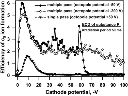
Could one control the position of the second maxi-mum in Figure 2 (bottom left) or is it an intrinsic
property of ion interaction with electron of given (high) energy? Figure 4 clearly shows that the position and appearance of second maximum is a function of elec-tron repelling electrode (transfer octopole) potential. Lower ECD efficiency for single-pass than multiple-pass is due to short electron irradiation period of 50 ms used for all measurements in Figure 4. The second maximum of ECD efficiency (and, in general, of ECD at high negative cathode potential) is not observed when octopole potential is positive (single-pass). Therefore, multiple-pass ECD (formation of c- and z-type ions) at high negative cathode potentials is probably not a result of high-energy electron induced ionization/dissociation. Formation of multiple-pass ECD product ions for high negative cathode potentials is possible and proceeds at rate comparable to that for typical ECD conditions if the cathode potential is not more negative than the repel-ling electrode (transfer octopole) potential. Figure 4
demonstrates that ECD product ions are observed over a wide cathode potential range (up to⫺100 V for ⫺200 V octopole potential and up to ⬃⫺60 V for ⫺50 V octopole potential). Therefore, ECD product ions are formed when electrons can be repelled and trapped in the ICR trap region. Presumably ECD proceeds with low-energy electrons produced by virtual cathode for-mation (electron energy loss due to multiple turns in crossed electric and magnetic fields). Local enhance-ment of ECD efficiency (second maximum inFigure 2, left) could be due to electron beam behavior, e.g., virtual cathode instabilities, under specific experimen-tal conditions. We note that similar behavior is
ob-Figure 3. Radical/prime c-type ion formation in ECD (shown for c5ions from substance P) as a
function of octopole potential, electron irradiation period and cathode potential. Formation of radical
c-type ions in multiple-pass but not in single-pass mode at a given cathode potential indicates a larger
served for shorter and longer electron irradiation peri-ods than 50 ms shown inFigure 4.
ECD with Hollow Electron Emitter
Figure 5 demonstrates the dependence of overall ECD
efficiency (probed with Substance P) on hollow cathode
ECD parameters (cathode potential and electron irradi-ation period) and distance from the ICR trap center. Magnetic field gradient is indicated by the blue line in
Figure 5. As discussed in the Methods section,
mount-ing the hollow cathode in the magnet frmount-inge field produces a compressed electron beam in the center of the ICR trap (Figure 1).Figure 5clearly shows that ECD
Figure 4. ECD efficiency as a function of cathode potential and octopole potential. The octopole potential amplitude determines ECD extent and efficiency at high negative cathode potentials.
20
25
30
35
40
45
50
55
60
65
0
2
4
6
8
10
12
14
16
18
-0.5 V 50 ms
-2 V 50 ms
-5 V 50 ms
-2 V 100 ms
Ucathode Period
9.4 T
1.4 T
Ma
gnetic
in
duction,
T
20
25
30
35
40
45
50
55
60
65
0
2
4
6
8
10
12
14
16
18
-0.5 V 50 ms
-2 V 50 ms
-5 V 50 ms
-2 V 100 ms
Ucathode Period
9.4 T
1.4 T
Ma
gnetic
in
duction,
T
Distance from the ICR trap center, cm
EC
D
effi
ci
ency
,
%
20
25
30
35
40
45
50
55
60
65
0
2
4
6
8
10
12
14
16
18
-0.5 V 50 ms
-2 V 50 ms
-5 V 50 ms
-2 V 100 ms
Ucathode Period
9.4 T
1.4 T
Ma
gnetic
in
duction,
T
20
25
30
35
40
45
50
55
60
65
0
2
4
6
8
10
12
14
16
18
-0.5 V 50 ms
-2 V 50 ms
-5 V 50 ms
-2 V 100 ms
Ucathode Period
9.4 T
1.4 T
Ma
gnetic
in
duction,
T
Distance from the ICR trap center, cm
EC
D
effi
ci
ency
,
%
Figure 5. Compressed hollow electron beam ECD efficiency as a function of distance from the ICR trap center (magnetic field shown in blue), electron injection period and cathode potential (electron energy).
efficiency drastically increases as the hollow cathode is moved away from the ICR trap. The precursor ion beam is on-axis in the ICR trap, so that there is little overlap with the hollow electron beam when its i.d. is⬃4.7 mm (20 –30 cm from the ICR trap center). Electron beam compression by the magnetic field becomes more pro-nounced as the cathode is moved into the magnet fringe field. ECD efficiency reaches its maximum (corresponds to the maximal ECD efficiency for a disk-shaped dis-penser cathode, namely ⬃18% to 20% for doubly charged Substance P) if the cathode is located in the field of⬃1.4 T (65 cm away from the ICR trap center). ECD dependence on various experimental parameters is similar for a disk dispenser cathode (o.d. 10 mm) and hollow cathode displaced by 65 cm axially from the ICR trap center (Figure 5). The 4.7 mm aperture of the hollow cathode allows for efficient on-axis IRMPD as noted earlier [28]. Therefore, the hollow cathode in magnet fringe field provides efficient on-axis ECD and IRMPD with the required optimum overlap of the three beams: ions, photons, and electrons. However, the drawbacks of the method (remote mounting of the electron emitter and very high power required for cathode operation) limit its implementation.
ECD with a Cold Electron Emitter
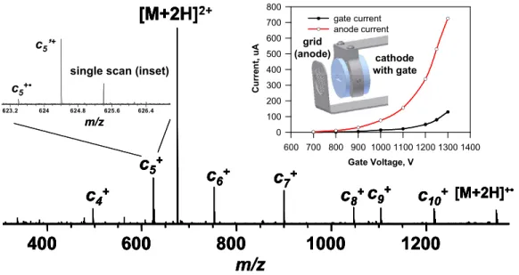
Successful proof-of-principle experiments with a cold electron emitter (see the Methods section) not only demonstrate the possibility of obtaining efficient ECD mass spectra (Figure 6), but also suggests the presence of low-energy electrons, based on formation of radical
c-ions (Figure 6, mass scale-expanded segment).
Elec-tron current and energy measurements performed with the cold electron emitter demonstrate electron current comparable to that obtained with thermal dispenser cathodes (Figure 6inset). ECD fragmentation (product ion distribution) for cold cathode ECD is similar to that for ECD with thermal cathodes at low electron energy (multiple-pass). Thus despite the wide electron energy dispersion (10–20 eV) and presence of high-energy elec-trons (10 –20 eV when cathode potential is at⫺(5–15) V) in the primary electron beam, trapping and cooling of electrons by multiple-pass evidently suffices to provide abundant low-energy electrons. Therefore, multiple-pass operation enables use of electron sources with wide electron energy dispersion and high average elec-tron energy for ECD. Advantages of the cold cathode compared with the thermal emitter are: no outgassing due to thermal heating of the surrounding parts; no blackbody irradiation when ECD is not active; and fast on-off switching. The drawbacks of cold-cathode ECD are mainly the high voltage (1–2 kV) pulses required for cathode operation. Increase of electron irradiation pe-riod above ⬃100 ms at high negative gate potential (⬃1.5–2 kV) was limited by electrical discharges pre-sumably between cathode nanotubes and gate elec-trode, resulting in reduced electron emission efficiency and subsequent damage to the emitting surface. There-fore, ECD of highly multiply charged precursor ions in top-down protein structural analysis might be more suitable for cold cathode applications because the req-uisite electron irradiation period is typically 10 times shorter than for ECD of doubly and triply charged peptides. Further improvements of cathode operation under high voltage pulses in the environment of FT-ICR
m/z
1000
1200
800
600
400
m/z 625.6 626.4 624.8 624 623.2c
5+c
5
’
+
[M+2H]
2+c
4+c
6+c
7+c
8+c
9+c
10+[M+2H]
+•single scan (inset)
substance P
100 ms
c
5
+•
m/z
1000
1200
800
600
400
m/z 625.6 626.4 624.8 624 623.2c
5+c
5
’
+
[M+2H]
2+c
4+c
6+c
7+c
8+c
9+c
10+[M+2H]
+•single scan (inset)
substance P
100 ms
c
5
+•
626.4 625.6 624.8 624 623.2 c5’+ 2+single scan (inset)
c5+• 626.4 625.6 624.8 624 623.2 c5’+ 2+
single scan (inset)
c5+• m/z Gate Voltage, V 600 700 800 900 1000 1100 1200 1300 1400 Cur re n t, uA 0 100 200 300 400 500 600 700 800 gate current anode current grid (anode) cathode with gate
m/z
1000
1200
800
600
400
m/z 625.6 626.4 624.8 624 623.2c
5+c
5
’
+
[M+2H]
2+c
4+c
6+c
7+c
8+c
9+c
10+[M+2H]
+•single scan (inset)
substance P
100 ms
c
5
+•
m/z
1000
1200
800
600
400
m/z 625.6 626.4 624.8 624 623.2c
5+c
5
’
+
[M+2H]
2+c
4+c
6+c
7+c
8+c
9+c
10+[M+2H]
+•single scan (inset)
substance P
100 ms
c
5
+•
626.4 625.6 624.8 624 623.2 c5’+ 2+single scan (inset)
c5+• 626.4 625.6 624.8 624 623.2 c5’+ 2+
single scan (inset)
c5+• m/z Gate Voltage, V 600 700 800 900 1000 1100 1200 1300 1400 Cur re n t, uA 0 100 200 300 400 500 600 700 800 gate current anode current grid (anode) cathode with gate
Figure 6. First ECD FT-ICR mass spectrum (Substance P) acquired with a non-thermal electron source. Electron irradiation period, 50 ms; gate potential during electron injection, 2 kV; cathode
potential,⫺5 V; grid potential, ⫹5 V. Radical c-type ions indicate the presence of low-energy electrons
in the electron beam (left inset). Electron emission current is comparable to that for a thermal dispenser cathode (right inset).
MS will be required to provide stable electron emission for long electron irradiation periods. Cold cathode operation in a D.C. regime can be obtained with the present cathodes and is a typical mode for operation in other applications.
Conclusions
Improved ECD performance obtained with thermal dispenser cathodes in 2001 accelerated further devel-opment of the method and its wide application in bottom-up and top-down mass spectrometry. Combi-nation with IRMPD, achieved with different experimen-tal geometries, added ion activation/dissociation capa-bilities and further broadened application areas and fundamental investigations of ion-electron interactions. Facing rapid ETD development, ECD preserves its niche in tandem mass spectrometry and demands fur-ther technical improvements.
In-depth comparison of single-pass and multiple-pass electron injection for ECD demonstrates that both can provide similar efficiency but single-pass requires 10 times longer electron irradiation period at the same cathode potential. Multiple-pass ECD clearly indicates the presence of low-energy electrons that presumably result from electron trapping and cooling between the negative potentials of the cathode surface and ion transfer optics. The presence of radical c-ions serves as an indicator of ion dissociation due to interaction with low-energy electrons that allow for pronounced hydro-gen atom transfer between ECD products in charge-reduced radical ion intermediates. Efficient electron trapping and cooling extends the range of cathode potentials suitable for peptide and protein analysis. We demonstrate that ECD at high negative cathode poten-tial is a function of electron repelling electrode (ion transfer octopole) potential and most probably pro-ceeds from low-energy electrons and not high-energy electrons as reported previously. ECD performance variation as a function of transfer octopole potential allows efficient ECD rate control to optimize the exper-iment timing, for instance for combined ECD/IRMPD applications in LC-MS/MS.
To improve the overlap of three beams (ions, pho-tons, and electrons) for efficient activation/dissociation of the same ensemble of ions, we introduced electron injection based on a hollow dispenser cathode mounted in the magnet fringe field. Magnetic field compression of the on-axis annular electron beam provided optimum performance for ECD and IRMPD as well as their combination. However, the high power required for large o.d. hollow cathode operation leads to strong outgassing and rapidly increases background pressure in and near the ICR ion trap.
To overcome the problem of outgassing due to thermal heating while generating a large diameter elec-tron beam, we implemented elecelec-tron injection based on cold electron emitter (field emission from carbon nano-tubes). High voltage pulsed operation of the cold
cath-ode demonstrated suitable performance in multiple-pass ECD. Observation of radical c-type ions indicated the presence of low-energy electrons in the trapped electron beam despite wide electron energy dispersion and high average electron energies in the primary electron beam. With several technological limitations still to be resolved, the future employment of cold electron emitters in low electron energy applications, for instance in ECD FT-ICR MS, appears quite promis-ing and advantageous.
Acknowledgments
The authors thank Melinda A. McFarland for helpful discussions. The authors acknowledge support for this work by Ecole Poly-technique Fédérale de Lausanne, the NSF National High-Field FT-ICR Mass Spectrometry Facility (DMR-00-84,173), Florida State University, and the National High Magnetic Field Laboratory at Tallahassee, Florida.
References
1. Zubarev, R. A.; Horn, D. M.; Fridriksson, E. K.; Kelleher, N. L.; Kruger, N. A.; Lewis, M. A.; Carpenter, B. K.; McLafferty, F. W. Electron Capture Dissociation for Structural Characterization of Multiply Charged Pro-tein Cations. Anal. Chem. 2000, 72(3), 563–573.
2. Cooper, H. J.; Hakansson, K.; Marshall, A. G. The Role of Electron Capture Dissociation in Biomolecular Analysis. Mass Spectrom. Rev.
2005,24(2), 201–222.
3. Tsybin, Y. O.; Ramstrom, M.; Witt, M.; Baykut, G.; Hakansson, P. Peptide and Protein Characterization by High-Rate Electron Capture Dissociation Fourier Transform Ion Cyclotron Resonance Mass Spec-trometry. J. Mass Spectrom. 2004, 39(7), 719 –729.
4. Sweet, S. M. M.; Cooper, H. J. Electron Capture Dissociation in the Analysis of Protein Phosphorylation. Expert Rev. Proteom. 2007, 4(2), 149 –159.
5. Breuker, K.; Oh, H. B.; Lin, C.; Carpenter, B. K.; McLafferty, F. W. Nonergodic and Conformational Control of the Electron Capture Dis-sociation of Protein Cations. Proc. Nat. Acad. Sci. U.S.A. 2004, 101(39), 14011–14016.
6. Syka, J. E. P.; Coon, J. J.; Schroeder, M. J.; Shabanowitz, J.; Hunt, D. F. Peptide and Protein Sequence Analysis by Electron Transfer Dissocia-tion Mass Spectrometry. Proc. Nat. Acad. Sci. U.S.A. 2004, 101(26), 9528 –9533.
7. Baba, T.; Hashimoto, Y.; Hasegawa, H.; Hirabayashi, A.; Waki, I. Electron Capture Dissociation in a Radio Frequency Ion Trap. Anal. Chem. 2004, 76(15), 4263– 4266.
8. Silivra, O. A.; Kjeldsen, F.; Ivonin, I. A.; Zubarev, R. A. Electron Capture Dissociation of Polypeptides in a Three-Dimensional Quadrupole Ion Trap: Implementation and First Results. J. Am. Soc. Mass Spectrom. 2005, 16(1), 22–27.
9. Pitteri, S. J.; Chrisman, P. A.; Hogan, J. M.; McLuckey, S. A. Electron Transfer Ion/Ion Reactions in a Three-Dimensional Quadrupole Ion Trap: Reactions of Doubly and Triply Protonated Peptides with SO2·⫺.
Anal. Chem. 2005, 77(6), 1831–1839.
10. Satake, H.; Hasegawa, H.; Hirabayashi, A.; Hashimoto, Y.; Baba, T. Fast Multiple Electron Capture Dissociation in a Linear Radio Frequency Quadrupole Ion Trap. Anal. Chem. 2007, 79, 8755– 8761.
11. Ding, L.; Brancia, F. L. Electron Capture Dissociation in a Digital Ion Trap Mass Spectrometer. Anal. Chem. 2006, 78(6), 1995–2000. 12. McAlister, G. C.; Phanstiel, D.; Good, D. M.; Berggren, W. T.; Coon, J. J.
Implementation of Electron-Transfer Dissociation on a Hybrid Linear Ion Trap-Orbitrap Mass Spectrometer. Anal. Chem. 2007, 79(10), 3525– 3534.
13. Xia, Y.; Chrisman, P. A.; Erickson, D. E.; Liu, J.; Liang, X. R.; Londry, F. A.; Yang, M. J.; McLuckey, S. A. Implementation of Ion/Ion Reactions in a Quadrupole/Time-of-Flight Tandem Mass Spectrometer. Anal. Chem. 2006, 78(12), 4146 – 4154.
14. Tsybin, Y. O.; He, H.; Emmett, M. R.; Hendrickson, C. L.; Marshall, A. G. Ion Activation in Electron Capture Dissociation to Distinguish Between N-Terminal and C-Terminal Product Ions. Anal. Chem. 2007, 79(20), 7596 –7602.
15. McFarland, M. A.; Chalmers, M. J.; Quinn, J. P.; Hendrickson, C. L.; Marshall, A. G. Evaluation and Optimization of Electron Capture Dissociation Efficiency in Fourier Transform Ion Cyclotron Resonance Mass Spectrometry. J. Am. Soc. Mass Spectrom. 2005, 16(7), 1060 –1066. 16. Tsybin, Y. O.; Hendrickson, C. L.; Beu, S. C.; Marshall, A. G. Impact of
Trans-form Ion Cyclotron Resonance Mass Spectrometry. Int. J. Mass Spectrom.
2006,255, 144 –149.
17. Chan, T. W. D.; Ip, W. H. H. Optimization of Experimental Parameter for Electron Capture Dissociation of Peptides in a Fourier Transform Mass Spectrometer. J. Am. Soc. Mass Spectrom. 2002, 13(12), 1396 –1406. 18. Mormann, M.; Peter-Katalinic, J. Improvement of Electron Capture Efficiency by Resonant Excitation. Rapid Commun. Mass Spectrom. 2003, 17(19), 2208 –2214.
19. Cournoyer, J. J.; Lin, C.; O’Connor, P. B. Gas-Phase Structure Dissimilarity of Protonated Isomeric Peptides Revealed by IR-Acti-vated DR-ECD. J. Am. Soc. Mass Spectrom., unpublished.
20. Tsybin, O. Y.; Tsybin, Y. O.; Hendrickson, C. L.; Quinn, J. P.; Marshall, A. G. Electron Capture Dissociation Implementation Evolution in FT-ICR Mass Spectrometry. Proceedings of the 54th ASMS Conference on Mass Spectrometry and Allied Topics; Seattle, WA, May, 2006.
21. Zubarev, R. A.; Kelleher, N. L.; McLafferty, F. W. Electron Capture Dissociation of Multiply Charged Protein Cations. A Nonergodic Pro-cess. J. Am. Chem. Soc. 1998, 120(13), 3265–3266.
22. Hakansson, K.; Emmett, M. R.; Hendrickson, C. L.; Marshall, A. G. High-Sensitivity Electron Capture Dissociation Tandem FTICR Mass Spectrometry of Microelectrosprayed Peptides. Anal. Chem. 2001, 73(15), 3605–3610.
23. Axelsson, J.; Palmblad, M.; Hakansson, K.; Hakansson, P. Electron Capture Dissociation of Substance P Using a Commercially Available Fourier Transform Ion Cyclotron Resonance Mass Spectrometer. Rapid Commun. Mass Spectrom. 1999, 13(6), 474 – 477.
24. Tsybin, Y. O.; Hakansson, P.; Budnik, B. A.; Haselmann, K. F.; Kjeldsen, F.; Gorshkov, M.; Zubarev, R. A. Improved Low-Energy Electron Injection Systems for High Rate Electron Capture Dissociation in Fourier Transform Ion Cyclotron Resonance Mass Spectrometry. Rapid Commun. Mass Spectrom. 2001, 15(19), 1849 –1854.
25. Palmblad, M.; Tsybin, Y. O.; Ramstrom, M.; Bergquist, J.; Hakansson, P. Liquid Chromatography and Electron-Capture Dissociation in Fourier Transform Ion Cyclotron Resonance Mass Spectrometry. Rapid Com-mun. Mass Spectrom. 2002, 16(10), 988 –992.
26. Tsybin, Y. O.; Hakansson, P.; Wetterhall, M.; Markides, K. E.; Bergquist, J. Capillary Electrophoresis and Electron Capture Dissociation Fourier Transform Ion Cyclotron Resonance Mass Spectrometry for Peptide
Mixture and Protein Digest Analysis. Eur. J. Mass Spectrom. 2002, 8(5), 389 –395.
27. Hakansson, K.; Chalmers, M. J.; Quinn, J. P.; McFarland, M. A.; Hendrickson, C. L.; Marshall, A. G. Combined Electron Capture and Infrared Multiphoton Dissociation for Multistage MS/MS in a Fourier Transform Ion Cyclotron Resonance Mass Spectrometer. Anal. Chem.
2003,75(13), 3256 –3262.
28. Tsybin, Y. O.; Witt, M.; Baykut, G.; Kjeldsen, F.; Hakansson, P. Com-bined Infrared Multiphoton Dissociation and Electron Capture Disso-ciation with a Hollow Electron Beam in Fourier Transform Ion Cyclo-tron Resonance Mass Spectrometry. Rapid Commun. Mass Spectrom.
2003,17(15), 1759 –1768.
29. Sze, S. K.; Ge, Y.; Oh, H. B.; McLafferty, F. W. Plasma Electron Capture Characterization of Large Dissociation for the Proteins by Top Down Mass Spectrometry. Anal. Chem. 2003, 75(7), 1599 –1603.
30. Zabrouskov, V.; Whitelegge, J. P. Increased Coverage in the Transmem-brane Domain with Activated-Ion Electron Capture Dissociation for Top-Down Fourier-Transform Mass Spectrometry of Integral Mem-brane Proteins. J. Proteome Res. 2007, 6(6), 2205–2210.
31. Horn, D. M.; Ge, Y.; McLafferty, F. W. Activated Ion Electron Capture Dissociation for Mass Spectral Sequencing of Larger (42 kDa) Proteins. Anal. Chem. 2000, 72(20), 4778 – 4784.
32. Mihalca, R.; van der Burgt, Y. E. M.; McDonnell, L. A.; Duursma, M.; Cerjak, I.; Heck, A. J. R.; Heeren, R. M. A. Combined Infrared Multipho-ton Dissociation and Electron-Capture Dissociation Using Colinear and Overlapping Beams in Fourier Transform Ion Cyclotron Resonance Mass Spectrometry. Rapid Commun. Mass Spectrom. 2006, 20(12), 1838 – 1844.
33. Lin, C.; Cournoyer, J. J.; O’Connor, P. B. Probing the Gas Phase Folding Kinetics of Peptide Ions by IR Activated DR-ECD. J. Am. Soc. Mass Spectrom., in press.
34. Blakney, G. T.; Robinson, D. E.; Ngan, V. L.; Kelleher, N. L.; Hendrick-son, C. L.; Marshall, A. G. Predator: A PCI Data Station for FT-ICR Mass Spectrometry. Proceedings of the 53rd ASMS Conference on Mass Spectrom-etry and Allied Topics; San Antonio, TX, June, 2005.
35. Tsybin, Y. O.; Witt, M.; Baykut, G.; Hakansson, P. Electron Capture Dissociation Fourier Transform Ion Cyclotron Resonance Mass Spec-trometry in the Electron Energy Range 0 –50 eV. Rapid Commun. Mass Spectrom. 2004, 18(14), 1607–1613.