Landfill of Dong Hoi and Bo Trach
MANUAL FOR OPERATIONS
Table of contents
1. INTRODUCTION... 4
2. LANDFILL OVERVIEW ... 6
2.1 Location... 6
2.2 Purpose ... 7
2.3. How the landfill will work?... 8
2.3.1 Bottom Liner System... 9
2.3.2 Cells ... 9
2.3.3 Storm Water Drainage ... 9
2.3.4 Leachate Collection System ... 9
2.3.5 Methane Collection System ... 10
2.3.6 Covering or Cap... 10
2.4 What’s happen to the waste in the landfill?... 11
2.4.1 Waste decomposition... 11 2.4.2 Landfill gas... 12 2.4.3 Leachate generation ... 12 2.5 Description of facilities ... 14 2.5.1 Entrance facilities... 14 2.5.2 Landfill area ... 14
2.5.3 Leachate treatment system... 14
3. OPERATIONS GUIDELINES... 16
3.1 Personnel ... 16
3.1.1 Employees’ assignment and responsibility ... 16
3.1.2 Landfill manager (1) ... 16 3.1.3 Landfill supervisors (1-2)... 17 3.1.4 Drivers (1-2) ... 17 3.1.5 Laborers (3-4) ... 17 3.1.6 Security guard (1-2) ... 18 3.1 7 Working hours... 18
3.2 Waste operations and handling ... 19
3.2.1 Waste registration ... 19
3.2.2 Working the cells... 20
3.2.3 Waste dumping and compacting... 21
3.3 Gas collection and discharge... 24
3.4 Rainwater Network ... 25
3.4.1 Rainwater collection... 25
3.4.2 Drainage network... 25
3.4.3 Drainage bottom layer... 26
3.4.4 Draining trench... 28
3.5 Leachate collection and treatment ... 29
3.5.1 Collection network... 29
3.5.2 Leachate treatment ponds ... 30
3.5.3 Leachate recycling ... 31
3.5.4 Ponds maintenance ... 32
3.6 Other maintenance works... 33
3.6.1 Tools ... 33
3.6.2 Equipment... 33
3.6.3 Facilities ... 33
3.6.4 Roads... 34
4. SAFETY ... 35
4.1 Injuries and accidents... 35
4.2 Personal safety equipment... 35
4.3 Potential hazard... 35
4.4 Waste fire ... 35
5. MONITORING AND INSPECTION ... 37
5.1 Flow measurement ... 39
5.2 Water quality ... 39
5.3 Air quality ... 40
5.4 Inspection... 40
6. FINAL COVER PLACEMENT... 41
List of figures and tables
Figure 1: Overall view of the landfill 6 Figure 2: Main elements of a landfill 8 Figure 3: Map of landfill facilities 15 Figure 4: Placing the plastic sheet 20 Figure 5: Typical cross-section of an operational road` 22 Figure 6: Gasses collection and discharge network 23 Figure 7: Drainage and rainwater network 26 Figure 8: Detail of drainage layer 27 Figure 9: Detail of drainage trench 28 Figure 10: Drainage/leachate connection management 29 Figure 11: Leachate treatment ponds 31 Figure 12: Details of protective layer in the ponds 33 Figure 13: Location of samplings 38 Figure 14: Detail of V-notch manhole G33 39 Figure 15: Cross section final cover 41 Figure 16: Detail of vent in the final cover 42
Table 1: Scenario of filling 7
Table 2: Staffing 16
Table 3: List of potential hazards 35
Table 4: Water samplings 39
Table 5: Air samplings 40
Table 6: Details of final cover 41
List of annexes
Annex 1: List of equipment, tools and material necessary for the landfill operations Annex 2: Summary Operations and Maintenance operations
Annex 3: Calculation of flow based on V-notch Annex 4: Registry of waste entrance
Annex 5: Daily report form
1. INTRODUCTION
The landfill of Dong Hoi and Bo Trach is an important component of the socio-economic development plan of the province of Quang Binh for the period 2001-2020 and it was a pre-requisite for upgrading Dong Hoi City to class III in 2003.
In 2007, after several years of planning and construction, the landfill was inaugurated and handed over to the authorities by the Project Management Unit. The landfill is ready to receive the waste from the city of Dong Hoi and the districts of Bo Trach.
The Manual for Operations describes the basic and necessary operations to manage and maintain efficiently the landfill. It provides the Landfill Manager with a tool to operate with ease the landfill facilities. The Manual is indicative and should encourage the Landfill Manager to develop his/her own methodologies to constantly improve the operations.
The Manual for Operations at the Landfill of Dong Hoi and Bo Trach is divided in three main parts:
1. The present introduction and the chapter 2 explain why such a Manual was prepared and introduces the basics of landfill functioning.
2. The guidelines for the operations in chapter 3 detail the daily procedures to maintain the landfill facilities in good condition, and how to handle the waste, while the chapter 4 deals with safety of the operations and the chapter 5 sets the basis of monitoring and inspection, and the chapter 6 describe the final cover placement.
3. The annexes provide additional details as well as templates for monitoring and control.
The Operations described in this Manual take into account the limited budget for operations; for instance operations that should be done on a daily basis, such as the waste cover, is proposed to be done on a weekly basis. It does not prevent the landfill manager from doing a more appropriate and better job.
Over the years, the operations and equipment should be adjusted to the quantity and quality of waste being accepted at the landfill and inclusion of recycling should be quickly envisaged, as it will reduce the amount of waste to be buried and hence the lifespan of the landfill. This may have significant and beneficial economic and environmental impacts. Such recycling facilities do not need to be costly to be efficient.
1. Wastes should be deposited and compacted in layers no thicker than 2-2.5m
2. Each day or each week, depending on the quantity of waste being added, the waste should be covered with approximately 10-15 cm of soil.
The Manual for Operations is presented in a folder with plastic sleeves, in order to make updates, changes and improvements easier for the landfill manager.
Dong Hoi, May 2007,
2. LANDFILL OVERVIEW
2.1 Location
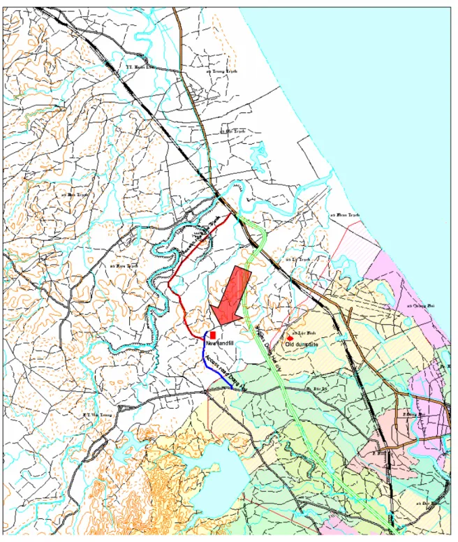
The landfill of Dong Hoi and Bo Trach is located in the commune of Ly Trach, in the district of Bo Trach, to the West of the city of Dong Hoi. It is accessible by two access roads from Bo Trach by the North-East and from Dong Hoi by the South-West. The figure 1 below is a map of the area with the placement of the landfill.
2.2 Purpose
The landfill will receive the waste from the municipalities of Dong Hoi and Bo Trach, and from other sources, such as private citizens and companies, health centres, hospitals and local companies. The landfill was designed with the latest knowledge and technologies and should be large enough to receive the waste during the next 15 to 20 years, taking into account the demography and the constant increase in quantity of collected waste.
The graph below (fig. 2) shows the scenario that served at dimensioning the landfill, and presented in the Feasibility Study of June 2005.
Table 1: Scenario of filling
Minimum and Maximum Scenario Waste Disposed at Landfill
Minimum Maximum Average Year Waste Waste Cumulative Waste Waste Cumulative Waste Cumulative
Generated Collected Settled Generated Collected Settled Collected Settled (ton/year) (ton/year) (m3) (ton/year) (ton/year) (m3/year) (ton/year) (m3)
2007 26,567 6,325 26,567 6,325 6,325 2008 27,369 6,679 30,052 7,799 7,239 2009 28,188 7,048 33,737 9,480 8,264 2010 29,025 7,430 6,316 37,633 11,383 9,675 9,407 7,996 2011 29,880 7,828 12,970 41,748 13,525 21,171 10,676 17,071 2012 30,754 8,241 19,974 46,093 15,924 34,707 12,082 27,341 2013 31,646 8,669 27,343 50,679 18,600 50,517 13,634 38,930 2014 32,558 9,114 35,090 55,517 21,572 68,852 15,343 51,971 2015 33,489 9,575 43,229 60,619 24,861 89,984 17,218 66,607 2016 34,439 10,054 51,775 65,996 28,491 114,202 19,272 82,988 2017 35,411 10,550 60,743 71,662 32,485 141,814 21,517 101,278 2018 36,402 11,064 70,147 77,630 36,868 173,152 23,966 121,649 2019 37,415 11,597 80,004 83,913 41,668 208,569 26,632 144,287 2020 38,417 12,221 90,392 87,276 45,395 247,155 28,808 168,773 2021 39,440 12,869 101,330 90,770 49,351 289,103 31,110 195,217 2022 40,485 13,540 112,840 94,401 53,546 334,617 33,543 223,728 2023 41,551 14,236 124,941 98,172 57,993 383,911 36,115 254,426 2024 42,639 14,958 137,655 102,090 62,706 437,210 38,832 287,433 2025 43,750 15,706 151,005 106,161 67,697 494,753 41,701 322,879 2026 44,883 16,480 165,013 110,390 72,982 556,788 44,731 360,900 2027 46,040 17,282 179,702 114,783 78,576 623,577 47,929 401,640 2028 47,221 18,112 195,098 119,347 84,493 695,396 51,303 445,247 2029 48,426 18,972 211,224 124,087 90,751 772,535 54,861 491,879 2030 49,656 19,861 228,105 129,011 97,367 855,297 58,614 541,701 2031 50,911 20,780 245,769 134,126 104,359 944,003 62,570 594,886 2032 52,191 21,732 264,240 139,439 111,746 1,038,987 66,739 651,614 2033 53,497 22,715 283,548 144,958 119,549 1,140,603 71,132 712,076 2034 54,830 23,732 303,720 150,691 127,786 1,249,222 75,759 776,471 2035 56,191 24,783 324,785 156,645 136,482 1,365,231 80,632 845,008
2.3. How the landfill will work?
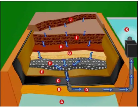
The basic parts of the landfill, as shown in Figure 2, are:
• Bottom liner system - separates waste and subsequent leachate from groundwater • Cells (old and new) - where the waste is stored within the landfill
• Storm water drainage system - collects rain water that falls on the landfill
• Leachate collection system - collects water that has percolated through the landfill itself and contains contaminating substances (leachate)
• Methane collection system - collects methane gas that is formed during the breakdown of waste
• Covering or cap - seals off the top of the landfill.
Each of these parts is designed to address specific problems that are encountered in the landfill. So, as we discuss each part of the landfill, we'll explain what problem is solved.
Figure 2: Main elements of a landfill
A. Groundwater B. Compacted soil C. Impervious liner
D. Leachate collection pipe E. Geotextile F. Protective layer G. Drainage layer H. Soil layer I. Old cells J. New cells K. Leachate ponds
2.3.1 Bottom Liner System
A landfill's major purpose and one of its biggest challenges is to contain the waste so that the waste doesn't cause problems in the environment. The bottom liner prevents the waste from coming in contact with the outside soil, particularly the groundwater. In Dong Hoi’s landfill, the liner is a durable, self-healing geosynthetic clay liner (GCL). The GCL is made of one layer of a mixture of sodium bentonite with an adhesive bound to an upper and lower geotextiles. Total thickness is about 5 to 6 mm. The sodium bentonite is a natural compound formed by volcanic ash. Hydraulic conductivity is very low, from 1x10⁻⁶ cm/sec for dry bentonite until 1x10⁻⁹ cm/sec when saturated.
2.3.2 Cells
Perhaps, the most precious commodity and overriding problem in a landfill is air space. The amount of space is directly related to the capacity and usable life of the landfill. If you can increase the air space, then you can extend the usable life of the landfill. To do this, waste is compacted into areas, called cells, which contain about one week's waste. This compression is done by the bulldozer that goes over the mound of waste several times. Once the cell is made, it is covered with 10 cm of soil and compacted further. Cells are arranged in rows and layers of adjoining cells (lifts).
2.3.3 Storm Water Drainage
It is important to keep the landfill as dry as possible to reduce the amount of leachate. This can be done in two ways:
• Exclude liquids from the solid waste. • Keep rainwater out of the landfill.
To exclude rainwater, the landfill has a storm drainage system. Plastic and concrete drainage pipes and trench collect water from areas of the landfill and channel it to outside and downstream the landfill area.
2.3.4 Leachate Collection System
No system to exclude water from the landfill is perfect and water does get into the landfill. The water percolates through the cells and soil in the landfill. As the water percolates through the waste, it picks up contaminants (organic and inorganic chemicals, metals, biological waste products of decomposition). This water with the dissolved contaminants is called leachate and is
To collect leachate, perforated pipes run throughout the landfill in a layer of gravel. These pipes then drain into a leachate pipe, which carries leachate to a leachate collection pond.
The leachate in the pond is allowed to settle, and is treated and decontaminated through successive anaerobic and aerobic processes, before being sent back into the landfill for further decomposition and evaporation. In addition, during the dry season, the recycled leachate will provide the necessary moisture to the waste to stabilize. Once the levels of various chemicals are at an acceptable level, the water can be released from the landfill.
2.3.5 Gases Collection System
Bacteria in the landfill break down the waste in the absence of oxygen (anaerobic) because the waste once compacted is airtight. A byproduct of this anaerobic breakdown is landfill gas, which contains approximately 50 percent methane and 50 percent carbon dioxide with small amounts of nitrogen and oxygen. This presents a hazard because the methane can explode and/or burn. So, the landfill gas must be removed. To do this, a series of pipes are embedded within the landfill to collect the gases that are discharged into the atmosphere.
2.3.6 Covering or Cap
As mentioned above, each cell is covered daily with at least 10 cm of compacted soil. This covering seals the compacted waste from the air and prevents pests (birds, rats, mice, flying insects, etc.) from getting into the waste and the generation of odors.
When a section of the landfill is finished, it is covered permanently with an impervious layer of natural clay and a layer of compacted soil. The soil is then planted with vegetation (grass) to prevent erosion of the soil by rainfall and wind. No trees, shrubs or plants with deep penetrating roots are used so that the plant roots do not contact the underlying waste and allow leachate out of the landfill, and rain getting in.
2.3.7 Groundwater Monitoring
During the landfill lifetime and beyond, the authorities will take samples of the groundwater for analysis. If the pH of the groundwater becomes acidic, that could indicate seeping leachate.
2.4 What’s happen to the waste in the landfill?
Waste put in a landfill will stay there for a very long time. Inside a landfill, there is little oxygen and limited moisture. Under these conditions, waste does not break down very rapidly. In fact, a lot of items present in the waste will decompose with difficulties and some may never totally disappear. Landfills are not designed to break down waste, merely to bury it. When a landfill closes, the site, especially the groundwater, must be monitored and maintained for up to 30 years!
2.4.1 Waste decomposition
Wastes are decomposed both through chemical reactions with landfill liquids and the action of bacteria and other microbes that occur naturally in the environment. Organisms feed on organic materials found in waste breaking them down into end products consisting primarily of:
• CO2 (carbon dioxide), • NH4 (ammonia), • CH4 (methane), • Humus, and • H2O.
The biological decomposition of solid waste follows three distinct phases:
PHASE 1: The microorganisms slowly degrade the complex organic portions of the waste using the O2 trapped during the landfilling process to form simpler organic compounds, CO2 and water. This phase is termed aerobic decomposition.
PHASE 2: After the CO2 is fully consumed, bacteria grow and decompose waste into simpler molecules such as hydrogen, ammonia, CO2 and organic acids. This second phase is step one of the anaerobic phase.
PHASE 3: In the third decomposition phase (step two of anaerobic phase), CH4 forming bacteria (methanotrops) utilize CO2, hydrogen and inorganic acids to form CH4 gas and other products.
Chemical reactions between wastes placed in landfills may also take place producing volatile constituents. Complete decomposition may take fifty years or more. However, conditions are such that rapid decomposition occurs mainly within the first five years.
2.4.2 Landfill gas
The gaseous end products produced in the most significant quantities are as follows:
CARBON DIOXIDE:
• Is highly soluble in water, forms carbonic acid,
• Dissolves iron from metal cans and lime from materials containing calcium, • Increases the hardness of water (including groundwater), and
• Is odorless and colorless.
METHANE:
• Travels upward through fill or along the path of least resistance into the atmosphere, pipes or building,
• Not very soluble in water, • Explosive, and
• Odorless, colorless and tasteless.
HYDROGEN SULFIDE:
• Creates odors (rotten egg) and a foul taste when dissolved in water, and
• In the presence of dissolved oxygen in the water, sulfide will be oxidized to tasteless and odorless sulfur and sulfates.
2.4.3 Leachate generation
In addition to the gases, landfills produce leachate. The amount of Leachate generated is directly affected by the amount of water that is allowed to enter the fill.
Water can enter the fill through:
• Moisture and liquids contained in wastes, • Poor surface water control,
• High water table, and • Inadequate cover.
Leachate usually contains elevated levels of: • Iron
• Organic Carbon (TOC) • Chloride • Dissolved solids • Sodium • Phosphorous • Calcium • Nitrogen • Magnesium
• Biological Oxygen Demand (BOD) • Sulfate
• Acid • Metals
2.5 Description of facilities
The landfill of Dong Hoi and Bo Trach is composed of three distinctive areas:
1. Entrance
2. Landfill area
3. Treatment ponds.
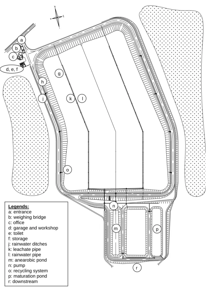
The figure 3 details the main facilities of the landfill.
2.5.1 Entrance facilities
The trucks bringing the waste are received at the main gate (a), where the waste is weighed at the weighing bridge (b). The supervisor that remains at the office (c), register the arrival in the logbook. The entrance facilities include the garage and workshop (d), the office and the toilets (e). A small room is reserved for storage of tools and others (f).
2.5.2 Landfill area
The trucks dump the waste inside the landfill area (g), using the operational roads (h). The rain is collected and diverted through a network of ditches (j). Inside the landfill area, there is a network of pipes that collects the leachate (k) and a separate network that collects the rainwater (l).
2.5.3 Leachate treatment system
The treatment ponds receive and treat the leachate coming from the landfill area. The first pond (m) favours the development of anaerobic bacteria to break down the toxics, remove organic nutrients, heavy metals, etc. The bottom of the pond will fill quickly and the sludge has to be regularly pumped back (n) to the landfill area, using the recycling system (o). The second pond serves at treating further the leachate using aerobic bacteria, which will remove bad smell. The leachate then flows to the third pond (p), where the leachate will mature before being safely discharged downstream (r).
Figure 3: Landfill facilities 2 3 4 a b c d, e, f g h j k l m n o p r Legends: a: entrance b: weighing bridge c: office
d: garage and workshop e: toilet f: storage j: rainwater ditches k: leachate pipe l: rainwater pipe m: anearobic pond n: pump o: recycling system p: maturation pond r: downstream
3. OPERATIONS GUIDELINES
3.1 Personnel
The landfill personnel consist of the persons working at the site on full or part-time basis. The skills, experience and motivation of the personnel are important factors to decide the success or failure of the operations. Failure of the operations will have a negative impact on the environment and on the image of the operating company.
3.1.1 Employees’ assignment and responsibility The composition of the personnel is as follows:
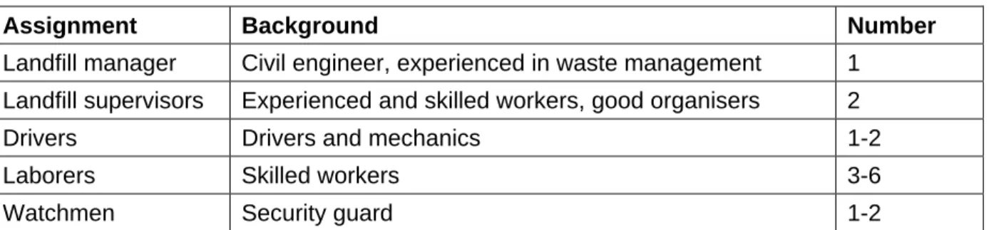
Table 2: Staffing
Assignment Background Number
Landfill manager Civil engineer, experienced in waste management 1 Landfill supervisors Experienced and skilled workers, good organisers 2
Drivers Drivers and mechanics 1-2
Laborers Skilled workers 3-6
Watchmen Security guard 1-2
The number of drivers and laborers can be flexible, depending on the working loads, the number of equipment that will be operated in parallel and if recycling activities take place before the final disposal of the fresh waste.
3.1.2 Landfill manager (1)
The landfill manager is the Director of the Landfill. He or she will have the following functions: • report to the Director of the Urban Works Company
• understand and update all national, provincial and city’s legal aspects on waste management and handling
• manage the personnel of the landfill
• ensure that the landfill is properly staff at the beginning of each day • contact and negotiate with the authorities
• plan and monitor the daily operations
• adjust and improve the operations and maintenance activities • adjust and improve safety and emergency procedures
• provide necessary training and coaching to new supervisors • order spare parts, equipment, material and tools
• prepare weekly, monthly, quarterly and annual reports, as required.
3.1.3 Landfill supervisors (1-2)
The landfill supervisors will be directly involved in the maintenance and operations activities.
They will have the following functions: • report directly to the landfill manager • register the arrival of waste
• supervise and participate in the daily operations of waste handling
• supervise and participate in the daily operations of maintenance of facilities, equipment and tools
• give first aid
• provide necessary training and coaching to new laborers, drivers and guards • instruct workers, drivers, guards
• prepare daily reports
3.1.4 Drivers (1-2)
The drivers will maintain and operate the bulldozer and any other wheeled or tracked equipment, as well as other additional tasks. They will have the following functions:
• report to the landfill manager
• operate and maintain the mobile equipment, bulldozer and wheel-loader • operate and maintain the electro-mechanical equipment and installations • participate in the daily operations of waste handling
• participate in the daily maintenance of facilities, equipment and tools • manage bulldozer/wheel-loader and other mobile equipment logbook.
3.1.5 Laborers (3-4)
The laborers will handle the operations related to the waste disposal, and will have the following functions:
• report to the landfill supervisors • assist the drivers’ activities • handle the waste
3.1.6 Security guard (1-2)
The security guards will take care of the facilities, during non-working hours or whenever a landfill manager or supervisor is not present at the landfill. They will have the following functions:
• report to the landfill manager
• watch over the facilities, equipment, tools and material • register the waste entering during non-working hours.
3.1 7 Working hours
Working hours at the landfill will be related to the hours that the site is being used by the Urban Works Company. Nevertheless, for safety reasons the landfill will be guarded 24/7 by watchmen.
The Landfill Manager will make assignments of working hours for each employee.
Each employee is responsible for adherence to assigned working hours. If an employee is unable to report at the proper time of day, he or she must notify the landfill manager ahead of his or her designated working time.
3.2 Waste operations and handling
All waste unloaded at the landfill must be supervised by landfill personnel. The purpose of this is to:
• prevent accidents,
• prevent unauthorized scavenging,
• ensure detection of problem or unauthorized wastes; and
• prevent unloading at a rate that exceeds the capacity of on-site equipment used for compaction and cover placement.
Supervision also allows vehicles to be unloaded in specified areas. Since it takes more time for a vehicle to be unloaded manually, an improperly positioned vehicle could slow down the number of vehicles able to unload at a busy site or time.
3.2.1 Waste registration
The trucks bringing the waste will enter the facilities through the main gate. They will register their load with the landfill supervisor. The truck will be weighted on the scale when entering the site and once more when exiting the site, after emptying.
The main information that needs to be logged are: • day and arrival time
• license plate of the truck • weight of the full truck
• type of waste (domestic, hospital, construction, industrial, chemical, bulky) • waste moisture (dry, moist, damped, soaked, liquid)
• waste origin (Dong Hoi, Bo Trach, other).
The supervisor will indicate to the drivers where to unload the waste and will informat with sufficient clarity to avoid the drivers making unnecessary manoeuvres. It may be useful, since unloading will occur in low light conditions, to indicate the position of the dumping zone with mobile posts and arrows.
When the truck leaves the site, it has to go on the weighing bridge again, and the second weight will be logged. The supervisor will then calculate the difference in weight and write it down.
3.2.2 Working the cells
Waste placing will be carried out in a way that optimises the operational area and minimises the nuisances; it means a small active area and a consecutive placing of waste and soil coverage.
The landfill will be divided into zones, to be filled sequentially from the northern part, near the gate, to the south, before the treatment ponds. The cells will have the following status:
• Unused zone: does not yet contain waste.
• Active zone: where waste is added on a daily basis, and the surface is periodically covered with soil
• Completed zone: where waste has reached its final level and its final cover has been completed.
Each cell will be made in several layers, called “lifts”. A waste lift can be of 3 to 5 meters high and is covered by an intermediate or final cover. Activities on the lift depend on the position of the lift within the cell: lower, medium or upper.
Working at the cells is different depending on the location of the cells. Cells that are directly in contact with the slopes of the landfill need the following preparatory works:
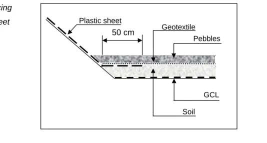
• Protecting the unprotected slopes of the landfill with plastic sheets.
The plastic sheet will protect the slope, which is not covered with impervious layer, against pollution with leachate. The leachate will flow on the surface of the sheet until the bottom of the landfill, and will get into the leachate collection pipes. The plastic sheet must be carefully laid and shall overlap with the GCL, below the gravel layer (see figure 5). The gravel will have to be removed and put back after the plastic sheet is laid. Overlap will be of minimum 50 cm. Before placing the sheets, the vegetation will be cut.
Figure 4: Placing the plastic sheet
50 cm Geotextile Plastic sheet
Pebbles
GCL Soil
The lower lifts at the bottom of the cells will need the following preparatory works:
• swapping the small gates in the manholes located at the bottom of the landfill from A to B (see figure …), directing the flow into leachate collection system.
3.2.3 Waste dumping and compacting
After the initial weighing, the truck will drive to the closest place where the active cell is located. Upon instruction of the workers, the waste will be dumped on the slope of the landfill from the access road, from the right or left side, depending on the location of the active cell. The driving on the bottom of the landfill is not recommended, as it will damage the drainage layer and the GCL. The bulldozer will push and spread the waste in layers no thicker than 30 cm and compact the layer several times thoroughly. The optimum compaction rate is achieved after 4 to 5 passes.
Good compaction will offer the following benefits: • less leachate is produced
• ulterior settlement of the final cover is minimised • landfill life is extended
• amount of blowing litter is reduced • runoff of surface waters is facilitated.
3.2.4 Waste cover
On a weekly basis, the waste in the active cell is covered with a 10-15cm layer of soil. The soil will be taken from the storages built with the original excavation material, located both sides of the landfill area. The soil will be trucked to the active cell and spread and compacted with the bulldozer.
The purpose of this cover is to:
• Reduce vectors - Fly eggs cannot emerge through 10 cm of soil. This also reduces the attractiveness for rats and birds.
• Litter control - No waste is exposed.
• Fire control - Glass left exposed to the sun can ignite other wastes. Cover also controls atmospheric oxygen and provides a fire barrier between cells.
• Provides a medium for vegetative growth. • Controls the movement of leachate and gases.
3.2.5 Construction of operational roads.
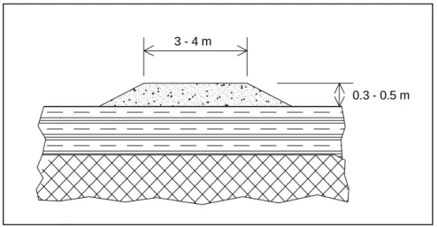
The trucks can use several operations roads to access to the active cell. Two roads, located East and West of the landfill, have already been built and will be used to access the cells located close to the landfill slopes. Additional operational all-weather roads (at least one in the middle!) will be built on top of the final cover and will be accessed from the Northern road. A typical cross-section is shown in figure 6 below. Demolition waste can be used as road foundation.
Figure 5: Typical cross-section of operations roads
Access for the working face is facilitated with the construction of turning places every 50 meters along the operations roads, so that the truck can drive backward and unload. Security measures will be taken to prevent the truck from backing too close to the edge of the working face, with the placement of logs or concrete curbs.
3.2 6 Hard-to-handle waste
Hard-to-handle waste will be accepted in the landfill, if no alternative and safer disposal method exists. Dangerous waste that is not accepted may finish in an uncontrolled way, causing severe environmental damage.
Construction waste: Construction waste is made mostly of inert material, not dangerous for the environment, such as stones, fragments of tiles, ceramic, concrete or wood. A smaller part may contain toxics, such as asbestos, paints and glues. Inert and non-biodegradable material (stones, concrete, etc.) can be used as foundation layer for the additional operational roads. Material with toxics should be manipulated with care (gloves, masks, boots) and buried in the middle of an active cell. Exposed glass wastes have been known to start landfill fires on sunny days and should be covered with waste or soil promptly.
0.3 - 0.5 m 3 - 4 m
Bulky wastes: Bulky wastes are large objects that can cause difficult compaction and long decomposition (mattress, furniture, etc.). Whole bulky items can cause uneven settlement which prevents adequate runoff or may create holes that accumulate gasses and/or leachate. Bulky waste should be dismantled, and some parts can be reused (wood, steel, etc.). The remains can be put in an active cell, after making sure that it can not perforate or damage the plastic layers at the slopes or/and the GCL at the bottom.
Hazardous waste: Hazardous waste is dangerous and toxic waste. It should be handled with extreme care and carefully mixed with daily waste in an active cell. The accumulation of toxic waste in one specific area of the landfill is not recommended, since it may cause a dangerous concentration of toxics and an augmented risk for the immediate environment. Dangerous waste, such as coming from health care centres and hospital, if not pre-treated, need to be placed in a container before being buried in an active and upper cell. If buried in a lower cell, there is a risk that the container is crushed by the overburden and the material released.
Sludge: Sludge coming from septic tanks will be spread over the waste at the upper lifts. A slow percolating process will promote the activities of the anaerobic bacteria for a faster decomposition of the waste. Small quantity of organic sludge can be used to aid in re-vegetation of the final cover. It cannot be used for weekly cover. Lime can be added to the sludge to neutralise bad smell.
3.3 Gases collection and discharge
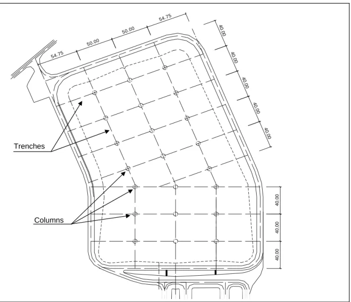
In parallel to the waste dumping, the gas collection and discharge network will be built. This network is three-dimensional and is composed of three main items:
• Vertical columns: the columns will be built at the same time the waste is dumped in the cells. A cylindrical steel form will be filled with coarse gravel (or construction waste). The steel form will be lift regularly by the bulldozer as the waste piles up.
• Horizontal gravel trench: the trenches will be dug at the top of the upper lift and will connect the vertical columns. The section of the trenches will be about 50/50 cm and will be filled with coarse gravel or construction waste. They will form a grid of about 40m x 40 m just below the final cover.
• Vents: at each crossing between columns and trenches, gasses discharge outlets will be built.
Figure 6: Gases collection and discharge network.
54.75 50.00 50.00 54.75 4 0 .00 40 .0 0 40 .0 0 40 .0 0 40 .0 0 40. 00 40. 00 40. 00 Columns Trenches
3.4 Rainwater Network
Rainwater in contact with the waste will be transformed into leachate, a highly polluted wastewater with a BOD5 that can measure up to 3’000 mg/L (domestic waste water has only 200 mg/L). Water in the waste will accelerate the decomposition process that produces the leachate. Thus, the design of the leachate and drainage intends to prevent rainwater and leachate from mixing.
3.4.1 Rainwater collection
At the bottom of the landfill, the rainwater collected from the unused zone is collected separately from the leachate and discharged outside the landfill. When a zone is inactive, the water flows in the rainwater drain and the connection to the leachate collection pipe is closed with a gate. When a zone is active or finished, the gate is moved to the other pipe connection and the leachate is diverted from the rainwater pipe to the leachate pipe (see fig. below). The landfill manager will make sure that the gates are swapped well in advance to avoid leachate mixing with rainwater.
3.4.2 Drainage network
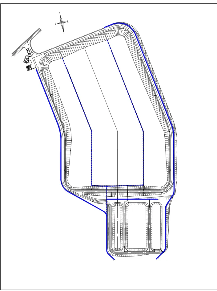
The landfill is surrounded with channels collecting the rainwater and directing it outside the landfill area. Because the runoff has never been in contact with the waste, it is still clean and can be safely discharged into the environment without prior treatment.
Drainage channels are made of concrete slabs that prevent erosion and facilitate the maintenance. Regular inspection and maintenance of the drains is needed on a weekly basis and after significant weather events, such as storms. The main purpose of the maintenance will be to keep the channels and pipes cleaned of sediment and in good working conditions.
Small repair will be made immediately, thus preventing further damage by erosion. During the first year of activity, a lot of erosion will occur and material will have to be removed from the drainage network. Afterwards the quantity of sediment should decrease, because most of the small particles will have been washed away. Make sure that the sediment is not stored in a place from when it can flow back into the network!
Culverts that cross the roads beneath will be checked regularly and cleaned of sediment whenever necessary. Any degradation that may imperil their solidity should be taken care seriously, as it could result in accidents and/or injuries.
Figure 7: Drainage and rainwater network
2
3 4
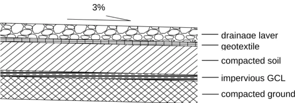
3.4.3 Drainage bottom layer
The bottom of the landfill is composed of:
• geo-synthetic Clay Liner (GCL) that is placed directly on the compacted ground • drainage layer, placed directly on the top of the liner.
The liner (GCL) is a waterproof barrier that contains the waste and prevents the leachate from contaminating the sub-soil and the water table. GCL is self-healing and small incisions and openings are immediately sealed off.
The drainage layer will function differently in unused zone and in active and completed zone. As long as the drainage layer is not covered with waste, it will serve at collecting the rainwater. As soon as it is close enough to an active or completed cell, it will collect the leachate.
Figure 8: Detail of drainage layer
The drainage layer at the bottom of the landfill has three main functions: • to protect the GCL from the sun and from being damaged
• to filter the leachate
• to bring oxygen to the leachate.
Maintenance works of the bottom layers will consist in:
• removing vegetation that could grow at the bottom; seeds and soil will be brought by birds and wind; roots will grow through the impervious layer and create path for the leachate to contaminate the subsoil.
• repairing the drainage layer with addition of gravel
• repairing the impervious layer in case of damage. In case the GCL is severely punctured, a patch will be placed.
drainage layer geotextile compacted soil impervious GCL compacted ground 3% 3%
If the liner is damaged (torn, punctured, etc.) during landfill operations, it is possible to repair it by placing a patch to fit over the damaged area (Figure …). The patch should be cut to size such that a minimum of overlap of 300 mm is achieved around all parts of the damaged area. Granular bentonite or mastic should be applied around the damage area prior to the placement of the patch. I may be necessary to use adhesive such as wood glue to affix the patch in place so that it is not displaced during the re-placement of the cover. Smaller patches also may be tucked under the damaged area to prevent patch movement.
3.4.4 Draining trench
In the middle of the landfill and beneath the bottom layers and, there is a drainage pipe in a trench that collects water. This is to prevent sub-pressure that may exercise unnecessary stress below the GCL. In case the GCL swells in presence of underneath water, it is a signal that the underneath pipe is clogged and needs clearance or repair.
Figure 9: Detail of draining trench
compacted ground GCL pebble
unground water
leachate rain water
3% 3%
geotextile
geotextile
3.5 Leachate collection and treatment
3.5.1 Collection networkThe leachate pipes collect the wastewater produced by the waste and drive it to the treatment ponds. As it was said before, the leachate should be collected through different pipes than the rainwater.
The network is composed of three main parts:
• the collectors located at the bottom of the landfill
• the pipes that receive the leachate from the collectors, lead to the ponds, and interconnect the ponds
• the leachate recycling system.
There are two parallel pipes with regularly-spaced manholes at the lowest parts of the landfill. A system of gates directs the water either to the rainwater pipe or to the leachate collectors.
Leachate usually carries a high load of sediment, and part of this sediment will deposit into the pipes. In dry and hot season, the amount of leachate will be small, and in particular circumstances, the sediment may dry and harden in the pipes. Manholes are placed are regular intervals along the leachate collector so that maintenance is easy and bamboo rods can be introduced into the pipes to stir the sediment and makes it moving again with the flow.
During the rainy season, the leachate will be much diluted and can be more easily treated through the system of ponds. Part of the flow can still be recycled for accelerating the decomposition of waste.
3.5.2 Leachate treatment ponds
The leachate will flow through a system of three ponds, alternatively anaerobic (pond 1), aerobic (pond 2) and maturation (pond 3).
Pond 1 – Anaerobic: The anaerobic pond is 2.5m deep and favours the development of bacteria that thrive in absence of oxygen. A large quantity of sludge is produced in this pond. A suction pump is placed at the bottom of the pond and will pump back the sludge to the landfill for recycling. The volume of the pond is about 5000 m3.
Pond 2 – Facultative pond: The water in the pond settles in three layers: the top layer is an aerobic zone, because there is oxygen brought by the wind and the sun; the anaerobic zone is the layer at the bottom of the pond where there is no oxygen and is a continuation of the treatment that started in the first pond; the middle layer is the facultative zone where both conditions exist in varying degrees. The volume of the pond is about 7000 m3.
Pond 3 – Maturation pond: The last pond, called maturation pond, is 80-100 cm deep and achieves the treatment of the leachate. The leachate will stabilise before it is released into the environment. At this stage, a small amount of sludge may still be produced, and the leachate is no longer toxic for the environment. Performance of the maturation pond can be improved with the addition of plants that are able to remove nutrients, as well as some variety of fish. Water hyacinth and carps should do well. Plants have to be regularly harvested and dumped into the landfill; plants and fish should not be used, because they accumulate heavy metals (lead, cadmium, mercury, etc.) in their organism and can be toxic. The volume of the pond is about 3000 m3.
Figure 11: Leachate treatment ponds
3.5.3 Leachate recycling
During the dry season, a small but highly concentrated amount of leachate will be produced. This leachate will be very difficult to treat in the ponds and shall be recycled and sprayed over the upper lifts. Flexible hose will be connected to the valves locate East and West along the roads and the leachate can be sprayed on top of the waste. In hot periods, the evaporation will make the leachate more concentrate but reduce the volume of liquid to recycle. It may be possible to recycle all the leachate produced in the landfill.
The operations of leachate recycling will be different during the rainy and dry periods:
a) During rainy period: the leachate will be diluted with rainwater and the DBO5 will be low. It is not necessary to add liquid to the waste, as it will receive regularly rainwater. Due to the low pollution load, the leachate will be easily treated through the system of ponds. Leachate will then be recycled whenever the waste is too dry and needs moisture.
b) During dry period: the leachate will be very strong with a high BOD5 and the system of ponds will treat it imperfectly. Leachate should be recycled. A flexible hose will connect to the closest valves and will spread the leachate on the waste at the upper lifts.
3.5.4 Ponds maintenance
The design and construction of the ponds ensure that the ponds are totally impervious and that no leachate will leak and migrate into the subsoil. The bottoms and the sides of the ponds are protected with a 2-mm HDPE liner. The liner needs a particular attention because it can easily be damaged if no proper care is taken when working around and in the ponds.
During the first year of operations, settlement of the ponds will occur and the HDPE liner will move slightly to adjust. Once the settlement is completed, let’s say after 2 years of operations, additional works will need to be done to protect the HDPD liner for the long term. The liner has to be covered and protected with a 5cm thick layer of stones or concrete slabs. Concrete and stones should be placed on a small layer of mortar, preventing sharp edges from puncturing the liner. Any concrete in contact with the leachate should have a percentage a silicate fume, which prevents the leachate from dissolving the cement.
Figure 12: Details of protective layer in the ponds
The whole system is designed so that the ponds can be individually emptied for maintenance. Ponds maintenance will necessitate emptying and should be organised whenever the flow of leachate is small or diluted.
The maintenance of the pond 1 necessitates the halt of the recycling activities; the maintenance of ponds 2 and 3 requires a constant recycling, because the reduction in volume of the whole system will lower its overall performance.
Maintenance activities will consist in:
• Removing the sludge deposited at the bottom and spreading it on the upper lifts in the landfill
300 mm
concrete tk. 50 - 70 mm chicken wire
• Repairing the HDPE liner
• Building the HDPE protection with stones and/or concrete • Clean and maintaining the pipes
• Maintaining the electro-mechanical equipment, such as pump, wires, etc. • Repairing and maintaining the roads around the ponds
• Repairing and maintaining the drainage network surrounding the ponds.
Downstream the ponds, there is a buffer zone, along which the treated leachate is released into the environment. This zone could be developed as an additional filter and filled with stones for a length of 50 meters or more.
3.6 Other maintenance works
The facilities and equipment have to be maintained in good working conditions at all time. Good and regular maintenance will lengthen the lifetime of the equipment and will reduce the overall cost of operating the landfill. In addition, it is safer and more comfortable for the drivers and labourers to use well-maintained equipment and tools.
3.6.1 Tools
A list of tools that are necessary for the general maintenance of the landfill is shown in Annex.. Small tools such as rakes, shovels, picks, mason’s tools, etc. will be cleaned at the end of each working day, and steel parts will be oiled at least once per month with waste engine oil. Tools’ oiling will protect the steel from rusting. Wooden handles will be changed whenever they are damaged or broken, because even a small splinter can cause infection and incapacitate a worker for several days, especially when handling waste. Tools will be put safely in the storage room whenever they are not being used.
3.6.2 Equipment
Equipment includes the pumps, diesel generator, trucks, bulldozer and wheel-loader, weighing bridge, etc. They will be maintained according to supplier/constructor specifications and recommendations.
3.6.3 Facilities
3.6.4 Roads
The access and operations roads will be maintained in good conditions, in order to avoid accident. The following maintenance activities are required:
• in case of erosion, stabilize the emplacement and replace the soil that was washed away, replant grass
• compensate settling with additional soil, compact thoroughly • maintain traffic signs, replace or repaint
4. SAFETY
4.1 Injuries and accidents
When normal safety rules are accepted, few accidents should occur. Nevertheless, accidents can happen when handling waste, tools or equipment.
The landfill office is equipped with a first-aid kit, and the supervisors should be trained in first aid intervention. Every minor wound will be immediately treated with disinfectant and protected from the dust. In case of serious and incapacitated injury, the person will be transported to the
hospital with the ambulance.
In case of accident caused by toxic matter, present in chemical/biological waste, a sample of the product has to be taken for analysis.
4.2 Personal safety equipment
Each personnel will receive safety equipment consisting of: • steel-top boots,
• safety gloves • helmet
• reflecting jacket.
4.3 Potential hazard
The table below describes the potential hazards associated with some wastes that may require special handling for disposal.
Table 3: List of potential hazards
Potential hazard Example waste
Personnel safety hazards Asbestos
Odor and vector problems Large dead animals
Excessive leachate generation Sewage sludge Excessive settlement in the landfill Yard debris
Puncturing or tearing the landfill liner Construction and demolition debris
Fire hazards Tire chips
Increased toxicity of leachate Cleanup materials contaminated with hazardous substances 4.4 Waste fire
Beware! The surrounding areas may not be stable. The rapid decomposition of refuse by burning may have created large voids underground. Underground fire may last for days and
The following safety procedures should be taken:
1. If an area is suspected of having an underground fire, block further access to the area and keep people away. Make sure everyone near the suspected fire is notified. If flames are present above ground, immediately notify the Fire Department and Forestry Office.
2. Try to stay upwind of any smoke and not breathe fumes, if any. Toxic fumes are not always visible and can be odourless.
3. Secure the site with cones, barriers, ribbon, etc. Be careful not to get too close if voids are suspected and ground may be unstable.
4. Bring heavy earth moving equipment (e.g. wheel-loader) to the site and uncover the burning waste as much as possible.
5. Smother the fire with soil.
5. MONITORING AND INSPECTION
The landfill is constructed in order to protect the environment, and the immediate surroundings of the landfill have to be regularly sampled and analysed, to make sure that it has no negative impact on the environment. The results will be compared to the standards TCVN. The sampling and analysis should be made together with a reputable agency and in coordination and supervised by DONRE.
The Environmental Impact Assessment (EIA) prepared in 2002 recommends taking samples and analyses the water and the air at several locations, as shown in fig. 12. Sampling and analysis will start as soon as the landfill is put into operations.
Results that are above the limit values of the TCVN standards should: • be checked again to make sure that it is not a mistake
• incite the landfill managers to investigate the causes and take timely action to reduce the negative environmental impact.
The results of flow measurement and samples analysis are best presented in form of graphics (excel) so that major trends and issues can easily be detected.
Figure 13: Location of sampling 2 3 4 Location of sampling Manhole G33
Discharge outlet of the treatment system Downstream 100 m away
Drilled well south of the treatment pond Leachate pipes (from the manholes)
5.1 Flow measurement
The inflow of leachate to the treatment ponds will be measured with the V-notch weir that equips the distribution manhole (G33) on the North of the ponds 1 and 2. To facilitate the access to regular measurement, the lid can be removed at all time; in this case the manhole should be protected with a small barrier to prevent accident or injury.
The flow will be measured daily. The height of water measured inside the V in cm (fig. 13) will give the corresponding flow according to the table in annex… Both the height and the corresponding flow should be recorded in the logbook.
Figure 14: Detail of V-notch in manhole G33
5.2 Water quality
The quality of the water will be analysed regularly, and compared with TCVN 5945-2005. Main parameters are DBO5 and the pH. Samples will be collected at the following locations:
Table 4: water samplings
No Details of location
1 inlet of leachate treatment system (manhole with V-notch) 2 outlet of leachate treatment system (outflow pond 3) 3 runoff 100 m downstream the ponds
4 underground water, through dug well
The following parameters will be analysed: pH, COD, BOD5, SS total, CrVl, N total, NH3, Coliform, Pb, P total, Cu, Mn, Zn, Cd and CN-.
100 mm 1 2 1 2 section 2-2 section 1-1 60 outflow inflow
Additional samplings taken before and after each pond will give good indications about the functioning and the effectiveness of the treatment system. Additional samplings should be organised at least once during the dry season and once during the rainy season.
5.3 Air quality
The quality of the air will be measured at 4 locations around the landfill:
Table 5: air samplings
No Details of location
5 control house – landfill gate
6 300 m downstream the non-dominant wind (blowing to North-East) 7 1000 m downstream the dominant wind (blowing to South-West) 8 at the nearest permanently inhabited house
The analysis will include: NH3, H2S, NO2, Dust, CH4, SO2, temperature.
5.4 Inspection
Visual inspection is the primary mean to detect environmental problems. The presence of fire, vermin or rodents are detected though visual inspection. Other visual aids include the presence of large amount of litter blown by the wind around the landfill, and the dark colour of the leachate spilling outside the leachate network. These are visual signals that some maintenance operations have to be planned and carried out.
Warning signs for subsurface fires may include:
• smoke and/or heat waves emanating from cracks and/or holes; • localised settlement;
6. FINAL COVER PLACEMENT
The final cover or cap will prevent the water from entering the waste and will accelerate anaerobic biodegradation processes. It is made of two layers.
Table 6: Details of final cover
Location Thicknes
s
Components Cross-section (Fig. 15)
Surface Common grass
Top layer 40 Soil stored at the
site added with compost produced on site
Bottom layer 60 Soil stored at the site with high percentage of clay, thoroughly compacted compacted clayey so ils (c lay conten t >30%) compacted soils
alluvial soils
grass
compacted wastes 3-5%
Prior to the final cover placement, the completed area should be cleared of all debris. Any object protruding through the daily or intermediate cover should be pulled out and the hole filled. Large cracks or holes in the surface should be filled with cover material. The network of channels and vents that collect gas will be completed.
The first and lower layer that is in contact with the waste will be made with an impermeable clay layer, or at least with sandy soil with a high content of clay. The final and top layer will be soil with enough organic parts on which grass will be planted to avoid erosion and for aesthetic purpose. The organic quality of the top layer can be improved with mixing with compost that can be produced on site. Grass will be preferably planted just before the rainy season starts. Trees and bushes should not be planted instead of grass, since the root will penetrate the impermeable layer and create paths for water.
Occasionally, leachate may seep through weak point in the covering and come out on to the surface. It appears black and bubbly. Later, it will stain the ground red. Leachate seepages are promptly repaired by excavating the area around the seepage and filling it with well-compacted
Once the cover is almost completed, the gasses discharge vents will be built, according to the construction details in fig. 14.
Figure 16: Detail of vent in the final cover
p la s t ic p ip e d ia . 1 0 0 m m g a s c o lle c tio n c h a n n e ls 3 0 0 x 3 0 0 m m , g r id 2 0 x 2 0 0 m 6 0 0 500 200 500 600 g r a s s a llu v ia l s o ils 300 c o m p a c te d s o ils c o m p a c te d c la y e y s o ils ( c la y c o n t e n t > 3 0 % ) c o m p a c te d w a s te s g a s c o lle c t io n c o lu m n r o u n d p r o f ile d ia .6 0 0
maintenance and operations
1. Equipment Description Unit No bulldozer p 1 front wheeled-loader p 1 truck 3.5 t p 1pressure washing unit p 1
mobile diesel pump p 1
mobile diesel generator p 1
handcart p 2
fire extinguisher p 2
first aid kit 2
2. Tools
Description Unit No
bulldozer maintenance tools set 1
loader maintenance tools set 1
wheelbarrow p 2 shovel p 5 rake p 5 pick p 3 hand compactor (?) p 1 mallet p 2 flat chisel p 2 pointed chisel p 2 bamboo rods 5 m p 2 saw p 1 plastic buckets 10 l p 5
masonry tools set 2
measuring tape 50 m p 1 metallic brush p 1 broom p 2 paint brush p 2 water hose 1” m 50 sickle p 2
cleaning tools set 1
3. Material
Description Unit No
cement Portland bag 5
silicate fume admixture kg 5
stones m3 1 sand m3 1 gravel m3 1 pebbles m3 1 bitumen kg 150 plastic sheets m2 500
steel formwork diam.1m p 1
reinforcement steel 8 mm kg 50
anti-rusting paint kg 2
fuel kg 250
machine grease kg 10
concrete stop curb m 10
cleaning product set 1
HDPE pipes 250 mm m 10
HDPE pipes 350 mm m 10
HDPE pipes 450 mm m 5
GCL m2 10
HDPE sheet 2 mm m2 20
ITEMS PERIOD
ACTIVITIES
MANPOWER
TOOLS
MATERIAL
Weighbridge daily sweeping and clean bridge 1 labourer broom water
monthly clean and grease lifting
mechanism
1 driver machine grease
yearly overall maintenance from supplier from supplier from supplier
Inside buildings daily sweeping 1 labourer broom water
weekly overall cleaning 1 labourer broom, brush, bucket,
cleaning kit
water, cleaning set
monthly small maintenance 2 labourers masonry tools, paint
brush
cement, paint, water
outside buildings weekly sweeping 1 labourer broom water
yearly overall maintenance 2 labourers masonry tools, paint
brush
cement, sand, paint, water
operations roads weekly check 1 supervisor
weekly clean 2 labourers broom
weekly repair shoulder erosion
and damages
2 labourers pick, shovel, hand
compactor, wheelbarrow
soil, grass
repair potholes 2 labourers pick, shovel, hand
compactor, wheelbarrow
gravel, asphalt
repair signposts 1 labourer metallic brush, paint
brush
anti-rusting paint, paint
drainage layers monthly check 1 supervisor
repair, remove grass 2 labourers shovel, wheelbarrow,
pick, compactor
soil, gravel
drainage channels after storm remove soil 2 labourers shovel, wheelbarrow
monthly check 1 supervisor
repair channels 2 labourers pick, shovel, hand
compactor, masonry
cement, sand, gravel, stones, water
compactor, masonry tools, wheelbarrow
stones,
reinforcements, water
rainwater pipes monthly check 1 supervisor
clean pipes 2 labourers bamboo rods, shovel,
wheelbarrow,
repair pipes 2 labourers shovel, saw grease, HDPE pipes,
glue
manholes monthly check 1 supervisor
clean 2 labourers shovel, wheelbarrow
yearly repair concrete 2 labourers masonry tools cement, admixture,
sand, gravel,
reinforcements, water
repair metal parts 1 labourer paint brush anti-rusting paint
leachate pipes weekly check 1 supervisor
clean pipes 2 labourers bamboo rods, shovel,
wheelbarrow,
repair pipes 2 labourers shovel, saw grease, HDPE pipes,
glue
Treatment ponds weekly check 1 supervisor
after two
years of operations
bypass ponds and build protection of HDPE liner
1 supervisor 3 labourers
masonry tools, chisel shovel, wheelbarrow
cement, admixture, sand, stones, water
monthly raise and clean pump 2 labourers hose, bucket, brush water
yearly empty and remove the
sludge
1 supervisor 3-4 labourers
shovel, buckets
Final Cover monthly check 1 supervisor
fill settlement 3-4 labourers wheelbarrow, shovel,
pick, compactor
soil, grass
water 2 labourers hose water, leachate
Surroundings weekly pick up blown items 1 supervisor
3-4 labourers
h [cm] Q [l/s] h [cm] Q [l/s] h [cm] Q [l/s] 0 0.000 4 0.431 11 4.615 0.5 0.002 4.25 0.501 11.5 5.157 0.75 0.007 4.5 0.578 12 5.736 1 0.013 5 0.753 12.5 6.353 1.25 0.024 5.5 0.955 13 7.007 1.5 0.037 6 1.187 13.5 7.700 1.75 0.055 6.5 1.450 14 8.433 2 0.076 7 1.746 14.5 9.207 2.25 0.102 7.5 2.074 15 10.021 2.5 0.133 8 2.438 15.5 10.877 2.75 0.169 8.5 2.836 16 11.776 3 0.210 9 3.272 16.5 12.717 3.25 0.256 9.5 3.746 17 13.703 3.5 0.309 10 4.258 17.5 14.732 3.75 0.367 10.5 4.811 18 15.807 h
Date: D: 12 M: 4 Y: 2007
Operator:
Thuyen Bui Chuyen
time in truck No waste origin waste type waste
moisture weight in [kg] weight out [kg] weighted waste [kg]
Driver’s name and signature
08:20 73-876 DH municipal dry 7454 3278 4176 Nguyen Tam Long
Date: D: 12 M: 4 Y: 2007
weather conditions sunny and hot with a slight breeze from the South
Landfill Manager Huong Cuong Long
Quantity of waste dumped [kg]
Dong Hoi [kg] Bo Trach [kg] Other [kg]
6455
4176 2279
(sludge) 0
Operations activities
- dumped in cell No 12 and covered with soil
- swap gate in manhole No G3
- move soil for final cover
Material utilised- 25 m3 of soil
Maintenance activities
- repair 10 potholes on west road
- fix up lid manhole No G3
- built 20 m2 stones protection in pond No 2
Material used- a bag of cement, 200 lt of sand and gravel, 3 kg
reinforcements
Observations
- lot of plastic bags in the forest on west side
- light smoke out of cell No 3
Actions - plan cleaning west forest on April 14
- plan digging waste and smother fire tomorrow 13
Other noticeable
events
- Labourer Tri was sleeping during working hours, gave
him warning
- scavengers came to collect recyclable items
Month of:
April 2007
Landfill Manager Huong Cuong Long
Quantity of waste dumped [kg]
Dong Hoi [kg] Bo Trach [kg] Other [kg]
127’890
87’980 25’570 14’340
Operations summary
Final cover completed for 50 m.
Maintenance summary
Completed stones protection pond No 2
Repair west road
Events summary
None
Priority next month:
Complete stones protection pond No 3
Restock: