HAL Id: hal-01829431
https://hal.archives-ouvertes.fr/hal-01829431
Submitted on 4 Jul 2018
HAL is a multi-disciplinary open access
archive for the deposit and dissemination of
sci-entific research documents, whether they are
pub-lished or not. The documents may come from
teaching and research institutions in France or
abroad, or from public or private research centers.
L’archive ouverte pluridisciplinaire HAL, est
destinée au dépôt et à la diffusion de documents
scientifiques de niveau recherche, publiés ou non,
émanant des établissements d’enseignement et de
recherche français ou étrangers, des laboratoires
publics ou privés.
Fabrication of TiO 2 Nanotanks Embedded in a
Nanoporous Alumina Template
Christophe Massard, S. Pairis, V. Raspal, Y. Sibaud, K. Awitor
To cite this version:
Christophe Massard, S. Pairis, V. Raspal, Y. Sibaud, K. Awitor. Fabrication of TiO 2 Nanotanks
Embedded in a Nanoporous Alumina Template. Journal of Nanomaterials, Hindawi Publishing
Cor-poration, 2015, 2015, pp.452148. �10.1155/2015/452148�. �hal-01829431�
Research Article
Fabrication of TiO
2
Nanotanks Embedded in
a Nanoporous Alumina Template
C. Massard,
1S. Pairis,
2V. Raspal,
1Y. Sibaud,
1and K. O. Awitor
11Clermont Universit´e, Universit´e d’Auvergne, C-Biosenss EA 4676, BP 10448, 63000 Clermont-Ferrand, France 2Institut NEEL, CNRS, Universit´e Grenoble Alpes, BP 166, 38042 Grenoble Cedex 9, France
Correspondence should be addressed to C. Massard; christophe.massard@udamail.fr Received 12 March 2015; Revised 18 May 2015; Accepted 24 May 2015
Academic Editor: Xiaosheng Fang
Copyright © 2015 C. Massard et al. This is an open access article distributed under the Creative Commons Attribution License, which permits unrestricted use, distribution, and reproduction in any medium, provided the original work is properly cited. The feasibility of surface nanopatterning with TiO2nanotanks embedded in a nanoporous alumina template was investigated. Self-assembled anodized aluminium oxide (AAO) template, in conjunction with sol gel process, was used to fabricate this nanocomposite object. Through hydrolysis and condensation of the titanium alkoxide, an inorganic TiO2 gel was moulded within the nanopore cavities of the alumina template. The nanocomposite object underwent two thermal treatments to stabilize and crystallize the TiO2. The morphology of the nanocomposite object was characterized by Field Emission Scanning Electron Microscopy (FESEM). The TiO2 nanotanks obtained have cylindrical shapes and are approximately 69 nm in diameter with a tank-to-tank distance of 26 nm. X-ray diffraction analyses performed by Transmission Electron Microscopy (TEM) with selected area electron diffraction (SAED) were used to investigate the TiO2structure. The optical properties were studied using UV-Vis spectroscopy.
1. Introduction
Nanostructured surfaces with the possible management of behavioral characteristics of the solid-liquid interface as well as their enormous surface area are critical in fields such as environment, health, electronics, IT, and energy. So, nanos-tructures are required to develop emerging technologies such as miniaturization of functional devices [1, 2] or to design more efficient materials [3–5]. The ability to produce nanos-tructures also allows developing devices [6, 7] that rely on physical principles that are missing at the microscopic scale such as quantum size effect. In some of emerging techno-logical applications, such as nanomedicine, fabricating the nanostructures is a great challenge and the key event to the achievement of the desired applications. Numerous tech-niques are nowadays available to build the nanostructures such as printing [8], molding [9], embossing [10], or anodic oxidation [11]. Hollow shaped nanostructures provide a plat-form to develop biomedical applications [12–14] and to store chemicals in nanocages [15–17]. In nanomedicine, nanocavi-ties can be useful to encapsulate therapeutic agents in order
to create drug delivery devices with controlled-release prop-erties [18,19]. Many methods are available to fabricate TiO2 nanotubes. The most commonly used are the electrochemical deposition methods [20], atomic layer deposition [21] and template assisted deposition [22]. Electrochemical anodiza-tions of titanium sheet are simple, cost effective methods. However, the obtained TiO2 nanotubes layers are generally not very ordered compared to AAO (anodic aluminum oxide) obtained by electrochemical anodization.
The hydro/solvothermal methods with or without tem-plates enable excellent control over the nanotube dimensions, including their wall thickness, diameter, and height. These approaches require a control of many parameters (solvent, annealing temperature) to be efficient. The atomic layer deposition requires more costly instruments. In this work, we demonstrate the feasibility of surface nanopatterning with TiO2 nanotanks embedded in a nanoporous template by combined electrochemical anodization and sol gel process. This approach is most cost effective, scalable (by changing the AAO nanomould size), and faster. The anodized aluminum oxide (AAO) templates elaborated in this study were used as
Volume 2015, Article ID 452148, 7 pages http://dx.doi.org/10.1155/2015/452148
2 Journal of Nanomaterials nanomoulds whereas the casting of an inorganic sol in the
nanopores leads to the TiO2 nanotanks buildings via a sol gel process after stripping apart the alumina nanomould. Our method ensures that our nanotanks are embedded in AAO templates which give the structure a more rigid base com-pared to anodized samples. In addition, the TiO2 sublayer strengthens the barrier layer.
2. Experimental Section
2.1. AAO Templates Synthesis. AAO templates were
fab-ricated using a two-step anodization process on a pure (99.999%) Al foil described in detail elsewhere [23–25]. First, the Al foil was anodized in 0.3 M oxalic acid solution at 40 V and 3∘C for 15 h to grow a thick porous oxide layer. The result-ing AAO film was then chemically stripped from the Al foil and a secondary anodization in the same oxalic acid solution at 40 V and 3∘C for 10 min was carried out. As-grown pore radii can be increased by chemical etching, without a notice-able change in the film thickness. This pore widening is linear in time with the diameters increasing about 6.6 nm per hour. Using this two-step technique combined with the etching process, good ordering is obtained over micron-sized regions and results in an AAO film approximately 400 nm in thick-ness with 50 nm pore diameters spaced 100 nm apart. A through-hole mask was prepared by separating the AAO film from the Al foil in a saturated HgCl2solution and removing the bottom alumina barrier layer in 5 wt.% phosphoric acid at 30∘C for 34 min. The remaining AAO was then lifted off onto the prepared wet TiO2 gel layer supported on various sub-strates.
2.2. Sol Preparation. The synthetic route of the sol chosen
here offered a simple method for the preparation of a sol suitable for the deposition of thin film by dip coating process. The sol was based on the dilution of the titanium (IV) butox-ide Ti(OBu)4 (3% molar) in anhydrous ethyl alcohol (97% molar), both supplied by Sigma Aldrich. The molar ratio was defined in order to obtain a suitable quality of titanium oxide [26].
2.3. Coating Procedure and Template Assembly. We prepared
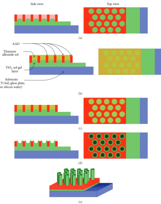
TiO2film coatings on various substrates, such as non-alkali glass plates, silicon wafers, and titanium foils, respectively, for XRD, UV-Vis, and SEM characterization. Every substrate was cleaned and degreased by immersion in 4 ultrasonic baths for 5 minutes containing, respectively, trichloroethylene, acetone, methyl alcohol, and deionized water. Samples were blow-dried under nitrogen flow. Just before the coating, the substrates were cleaned with optical paper and ethyl alcohol. Figure1shows the schematic procedure for preparation of TiO2 nanotanks embedded in a nanoporous alumina tem-plate. The starting point is a titanium foil. A thin layer of TiO2 is deposited by dip coating. The AAO template with both sides opened is then lifted to the wet inorganic TiO2coating (Figure 1(a)). The AAO nanocavities are filled with the titanium alkoxide sol (Figure1(b)). The sol in excess at the surface is wiped using optical paper (Figure1(c)). The assem-bly is then heat-treated in order to densify the relief and to
crystallize the titanium oxide. A development step is then applied in order to partially remove AAO template (Fig-ure 1(d)). We obtained TiO2 nanotanks embedded in a nanoporous template (Figure1(e)).
2.4. Annealing Treatment. After 20 minutes of air drying at
room temperature, the samples were first heat-treated in an oven at 130∘C for one hour under air. This first curing step allowed stabilizing the titanium oxide layer and also remov-ing volatile organic solvent. The second part of the annealremov-ing took place in a tubular furnace at 500∘C for one hour under air in order to obtain crystallized titanium dioxide material. A crystallized material was found to be less sensitive to the chemical stripping reagents used to remove partially the alumina nanomould than the amorphous counterpart.
2.5. Scanning Electron Microscopy. The samples were
char-acterized by a Field Emission Scanning Electron Microscope (FESEM) from ZEISS ultra+ (ZEISS-Germany) used with a low voltage (900 V and 3 kV) to limit charge effects. The working distance was from 2.5 mm to 6 mm. Samples were observed on a flat view or with a various tilt angle (33∘ and 40∘). Pictures were obtained with the secondary electron detector in-lens. Theses characterizations were carried on at the Neel Institute of Grenoble.
2.6. Transmission Electron Microscope and X-Ray Microanal-ysis. For detailed analysis of the nanotanks, a CM300 Philips
Transmission Electron Microscope (TEM) equipped with an X-ray microanalysis system by energy dispersion (Bruker EDX system SDD X-Flash 5030 detector) was used. The energy of the electrons is 300 KeV, leading to a wavelength of about 0.0196 ˚A. Images and electron diffraction patterns are obtained in selected area on aggregate with a TVIPS-F416 camera (4 k × 4 k 16 bits). Samples were prepared by scratching the surface which was rinsed with ethanol. The ethanol solution with nanoobjects was filtered using a 3 mm copper TEM grid covered with an amorphous carbon mem-brane with holes.
2.7. XRD Analysis. The crystalline structure of the TiO2
layers was determined by XRD using a Philips X’pert Pro diffractometer with Cu K𝛼 radiation.
2.8. UV-Vis Spectroscopy. Transmission spectra of the
sam-ples coated on silicon were recorded from 200 to 900 nm with a resolution of 2 nm using a Perkin Elmer Lambda 35 spectrometer.
3. Results and Discussion
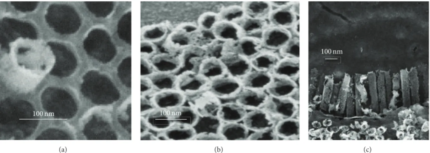
3.1. AAO Templates as Nanomould. Figure2(a)shows a
top-down SEM image of a typical nanoporous alumina template. This image indicates pore regularity with good hexagonal order. The resulting sample is roughly 10 mm × 10 mm in size, presenting a good uniformity. Figure 2(b) shows an oblique angle view from which the template thickness𝐻 was measured (𝐻 = 500 nm in this case). Considering the good regularity of the synthesized nanoporous structure previously
Top view Side view
(a)
Substrate (Ti foil, glass plate,
or silicon wafer) AAO
layer Titanium alkoxide sol
TiO2sol gel
(b)
(c)
(d)
(e)
Figure 1: Schematic procedure for preparation of TiO2nanotanks embedded in a nanoporous alumina template: (a) the AAO template with both sides opened is lifted to the wet inorganic TiO2coating. (b) The AAO nanocavities are filled with the titanium alkoxide sol. (c) The sol in excess at the surface is wiped. (d) After the annealing, a development step is then applied in order to remove partially AAO template. (e) TiO2nanotanks embedded in an AAO nanoporous template are obtained.
depicted, the AAO template was a good candidate to be used as a nanomould for building the TiO2nanotanks.
Figure3shows FESEM micrographs of the TiO2 nano-tanks embedded in AAO template as described in Figure1. Figure 3(a) shows the whole assembly. Figure 3(b) shows the top-down images of the hexagonal arrangement of the nanotanks resulting from the hexagonal pore structure in the AAO template. The ordered TiO2nanotanks are approx-imately 69 nm in diameter with a tank-to-tank separation of 26 nm. The SEM pictures of as-grown AAO in Figure2show
the AAO template with 50 nm diameter. A free-standing through-hole membrane may then be obtained by getting rid of the bottom barrier layer. This was achieved by chemical dissolution. The layer turns into a permeable membrane. This process increases the pore radii of the through-hole AAO template. So the diameter of nanotanks is around 69 nm in agreement with the through-hole AAO template diameter. Figure3(c)shows a 33∘oblique angle FESEM view of the TiO2 nanotanks. This picture shows fallen nanotanks occurring during the AAO unmolding process. The approximate height
4 Journal of Nanomaterials
200 nm
(a)
200 nm
(b)
Figure 2: Secondary electron (FESEM) images obtained with the secondary electron detector, in-lens, of a nanoporous alumina template: (a) top view and (b) oblique view.
100 nm (a) 100 nm (b) 100 nm (c)
Figure 3: FESEM (secondary electron collected with the in-lens detector) micrographs of the TiO2nanotanks embedded in AAO template. (a) TiO2 nanotanks embedded in AAO template. (b) Image of the hexagonal arrangement of the nanotanks. (c) View of the fallen TiO2 nanotanks.
determined from the image showing fallen nanotanks was found to be 440 nm. From these images, it can be seen that the TiO2nanotanks have cylindrical shapes with porous surface.
3.2. Transmission Electron Microscope and X-Ray
Microanal-ysis. A TEM image of a TiO2 nanotank is presented in
Figure4. The nanotank appears as a stack of spherical-like grains crammed together. These kinds of elementary grains are roughly 90 nm thick in diameter. Because of this granular morphology, the nanotank’s surface exhibits a rough and porous surface. EDX-MET spectrum is presented in Figure5. The major peaks match with titanium and oxygen species and are relative to the elaborated titanium dioxide nanotanks. Copper peaks come from the copper grid used as specimen holder. Sometimes aluminum, phosphor, and silicon traces are detected. Theses traces are the result of the different chemicals used in the synthesis protocol. The crystallinity of the TiO2 nanotanks structures are determined by indexing the diffraction pattern obtained (see Figure6). Rings on the diffraction patterns are indexed by anatase phase I41/amd (S.G.: 141; a = 3,7852 ˚A, c = 9,514 ˚A; pattern 00-021-1272) (labels are reported on it). The experimental data are in good agreement with the standard 021-1272 concerning anatase.
100 nm
Figure 4: TEM image of the TiO2nanotank surface.
3.3. XRD Analysis. Figure7summarizes the X-ray
charac-terization of TiO2layers on quartz substrate before and after annealing at 500∘C in air for 2 h. The unannealed TiO2layer is amorphous. In order to convert the TiO2layer to a crystalline phase, the sample was annealed in air at 500∘C in increments
0 500 1000 1500 2000 2500 3000 3500 4000 4500 5000 0 1 2 3 4 5 6 7 8 9 10
Peak “0” = electronic noise
Ti-L𝛼 O-K𝛼 Cu-L𝛼 Ti-K𝛼 Ti-K𝛽 Cu-K𝛼 Cu-K𝛽 Co u n ts Energy (keV)
Figure 5: MET-EDX spectra of the TiO2nanotanks.
101 004 200
211 204 116 + 220
1/(0.05 nm)
Figure 6: Diffraction pattern of the TiO2nanotanks.
of 50∘C. We observe the characteristic line of anatase (1 0 1). Crystallite size was calculated using the Scherrer formula
𝐷 = 0.94𝜆
𝛽 cos 𝜃, (1)
where 𝜆 is the wavelength of the CuK𝛼1 line, 𝜃 is the Bragg diffraction angle, and𝛽 is the full-width at half-max (FWHM) of a peak. We calculated the crystallite size by using the FWHM of the anatase (1 0 1). The average crystal size is about 64 nm. These data are in the same order of magnitude with the crystallite size evaluated from the TEM images.
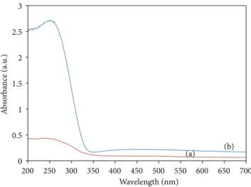
3.4. UV-Vis Spectroscopy. Figure8plots the UV-Vis
absorb-ance spectra for quartz substrate alone and quartz substrate coated with thin film layer stabilized at 130∘C for 1 hour. The curve for TiO2thin film layer shows considerable absorption for wavelengths below 330 nm which is in good agreement with previous studies [27].
A deviation of band gap energy is obtained on the nanotank titanium dioxides. This is a consequence of the weak thickness of our nanostructured layer. This result was observed elsewhere [28].
3.5. Discussion. We have obtained TiO2 nanotanks using
AAO template as nanomould. The approach followed here enables the fabrication of nanocylinders arrays at the surface
0 2000 4000 6000 8000 10000 12000 14000 20 30 40 50 60 70 80 Re la ti ve in te n si ty (101) (b) (a) 2𝜃 (deg)
Figure 7: X-ray diffraction patterns of TiO2 layers on quartz substrate: (a) as grown, (b) annealed at 500∘C.
0 0.5 1 1.5 2 2.5 3 200 250 300 350 400 450 500 550 600 650 700 A b so rba n ce (a.u .) Wavelength (nm) (b) (a)
Figure 8: UV-Vis spectra for (a) quartz substrate coated with TiO2 thin film layer, (b) quartz substrate alone layer (reference).
of an inorganic coating. TEM images exhibit hollow shaped structures. The titanium alkoxide sol used to fill in the AAO template is responsible for establishing theses cavities. During the annealing step, a TiO2 gel is formed within the AAO templates. Considering the high amount of volatile organic compound in the sol, evaporation during the heat treatment is responsible for the cavities genesis in the nanocylinders. After a development step, the AAO template is partially removed in order to exhibit the so-called nanotanks consisting in TiO2 hollow nanocylinders ruffling a base alumina. In comparison with conventional TiO2nanotubes layers obtained by electro-chemical anodization, we highlighted a more regular shape of the TiO2 nanotanks as a consequence of the growing of the TiO2 nanotanks into cylindrical AAO nanomoulds (see Figure9). This geometrical improvement of the shape is an advantage of the combined electrochemical anodization and sol gel process.
These hollow nanostructures are interesting in building future drug delivery platform. In previous works, we have
6 Journal of Nanomaterials
200 nm
(a)
100 nm
(b)
Figure 9: FESEM (secondary electron collected with the in-lens detector) micrographs of the TiO2comparison: (a) image of conventional TiO2nanotubes layers obtained by electrochemical anodization [11], (b) TiO2nanotanks embedded in AAO template.
demonstrated that TiO2nanotubes obtained by electrochem-ical anodization could act as cefuroxime carriers [29]. During the same annealing treatment, a crystallization process of the TiO2inorganic backbone occurs, providing an anatase struc-ture to the synthesized nanotank relief. Our surface nanos-tructuration, combining electrochemical process and sol gel route, can also be a photoactive device to inhibit bacterial adhesion [30–34].
4. Conclusion
We demonstrate the feasibility of surface nanopatterning with TiO2 nanotanks embedded in a nanoporous template by combined electrochemical anodization and sol gel process. The ordered crystallized TiO2nanotanks obtained have cylin-drical shape and are approximately 69 nm in diameter with a tank-to-tank separation of 26 nm.
The nanotanks obtained are promising candidates for further applications concerning nanoconfinement and drug administration: the embedded TiO2nanotanks are a stiff and protective nanocage which can be used to store and protect different molecular species of interest.
Furthermore, the anatase structure of the TiO2 material exhibits photocatalytic properties. If required, an UV irradi-ation of the nanostructure can provide a bactericidal effect: each cavity can own a self-cleaning surface, without the use of disinfection chemical products that might interfere with the stored molecules.
So our new synthesis method is a contribution to the building of well defined TiO2 nanotanks with a cylindrical geometry. The geometrical uniformity of our TiO2nanotanks is a consequence of the use of nanoporous alumina template as nanomoulds.
The growing of TiO2nanotanks in AAO template by com-bining anodization technique and sol gel process ensures a better geometrical definition of the TiO2nanotanks obtained compared to classical anodization of titanium. Monodisperse hollow nanocylinders consisting of crystalline titania parti-cles have been already prepared in a porous alumina mem-brane by a deposition technique using an aqueous solution system of titanium tetrafluoride. The main difference with our approach is the previous deposition of a titanium oxide gel layer. This film ensures a better anchoring for the coming TiO2nanotanks, in order to obtain arrays of TiO2nanotanks with a preferential orientation.
Conflict of Interests
The authors declare that there is no conflict of interests regarding the publication of this paper.
Acknowledgments
The authors thank Joel Cellier for the XRD measurements and the Neel Institute of Grenoble for FESEM and TEM microscopies and X-ray microanalysis.
References
[1] A. Mart´ınez-Otero, E. Evangelio, R. Alib´es et al., “Surface-structured molecular sensor for the optical detection of acidity,”
Langmuir, vol. 24, no. 7, pp. 2963–2966, 2008.
[2] P. Hu, J. Zhang, L. Li, Z. Wang, W. O’Neill, and P. Estrela, “Car-bon nanostructure-based field-effect transistors for label-free chemical/biological sensors,” Sensors, vol. 10, no. 5, pp. 5133– 5159, 2010.
[3] Y.-G. Guo, Y.-S. Hu, W. Sigle, and J. Maier, “Superior electrode performance of nanostructured mesoporous TiO2 (Anatase) through efficient hierarchical mixed conducting networks,”
Advanced Materials, vol. 19, no. 16, pp. 2087–2091, 2007.
[4] Y. Jin, Y. Shen, and S. Dong, “Electrochemical design of ultrathin platinum-coated gold nanoparticle monolayer films as a novel nanostructured electrocatalyst for oxygen reduction,”
Journal of Physical Chemistry B, vol. 108, no. 24, pp. 8142–8147,
2004.
[5] S. Zhang, D. M. Marini, W. Hwang, and S. Santoso, “Design of nanostructured biological materials through self-assembly of peptides and proteins,” Current Opinion in Chemical Biology, vol. 6, no. 6, pp. 865–871, 2002.
[6] P. Caroff, C. Paranthoen, C. Platz et al., “High-gain and low-threshold InAs quantum-dot lasers on InP,” Applied Physics
Letters, vol. 87, Article ID 243107, 2005.
[7] H.-J. Choi, J. C. Johnson, R. He et al., “Self-organized GaN quantum wire UV lasers,” The Journal of Physical Chemistry B, vol. 107, no. 34, pp. 8721–8725, 2003.
[8] L. Jiao, B. Fan, X. Xian, Z. Wu, J. Zhang, and Z. Liu, “Creation of nanostructures with poly(methyl methacrylate)-mediated nan-otransfer printing,” Journal of the American Chemical Society, vol. 130, no. 38, pp. 12612–12613, 2008.
[9] H. Xu, N. Lu, D. Qi et al., “Biomimetic antireflective Si nanop-illar arrays,” Small, vol. 4, no. 11, pp. 1972–1975, 2008.
[10] Z.-K. Shen, Z.-H. Chen, Z.-J. Qiu et al., “Influences of emboss-ing technology on Pb(Zr0.3,Ti0.7)O3 ferroelectric thin film,”
[11] K. O. Awitor, S. Rafqah, G. G´eranton et al., “Photo-catalysis using titanium dioxide nanotube layers,” Journal of
Photochem-istry and Photobiology A: ChemPhotochem-istry, vol. 199, no. 2-3, pp. 250–
254, 2008.
[12] S. E. Skrabalak, J. Chen, L. Au, X. Lu, X. Li, and Y. Xia, “Gold nanocages for biomedical applications,” Advanced Materials, vol. 19, no. 20, pp. 3177–3184, 2007.
[13] K. K. Perkin, J. L. Turner, K. L. Wooley, and S. Mann, “Fabri-cation of hybrid nanocapsules by calcium phosphate mineral-ization of shell cross-linked polymer micelles and nanocages,”
Nano Letters, vol. 5, no. 7, pp. 1457–1461, 2005.
[14] A. Vinu, M. Miyahara, V. Sivamurugan, T. Mori, and K. Ariga, “Large pore cage type mesoporous carbon, carbon nanocage: a superior adsorbent for biomaterials,” Journal of Materials
Chemistry, vol. 15, no. 48, pp. 5122–5127, 2005.
[15] O. V. Pupysheva, A. A. Farajian, and B. I. Yakobson, “Fullerene nanocage capacity for hydrogen storage,” Nano Letters, vol. 8, no. 3, pp. 767–774, 2008.
[16] Z. Wang and X. W. Lou, “TiO2nanocages: fast synthesis, interior functionalization and improved lithium storage properties,”
Advanced Materials, vol. 24, no. 30, pp. 4124–4129, 2012.
[17] T. Oku, M. Kuno, and I. Narita, “Hydrogen storage in boron nitride nanomaterials studied by TG/DTA and cluster calcula-tion,” Journal of Physics and Chemistry of Solids, vol. 65, no. 2-3, pp. 549–552, 2004.
[18] C. Pinto Reis, R. J. Neufeld, A. J. Ribeiro, and F. Veiga, “Nanoen-capsulation I. Methods for preparation of drug-loaded poly-meric nanoparticles,” Nanomedicine: Nanotechnology, Biology,
and Medicine, vol. 2, no. 1, pp. 8–21, 2006.
[19] A. Kumari, S. K. Yadav, and S. C. Yadav, “Biodegradable poly-meric nanoparticles based drug delivery systems,” Colloids and
Surfaces B: Biointerfaces, vol. 75, no. 1, pp. 1–18, 2010.
[20] P. Roy, S. Berger, and P. Schmuki, “TiO2nanotubes: synthesis and applications,” Angewandte Chemie International Edition, vol. 50, no. 13, pp. 2904–2939, 2011.
[21] M. S. Sander, M. J. Cˆot´e, W. Gu, B. M. Kile, and C. P. Tripp, “Template-assisted fabrication of dense, aligned arrays of tita-nia nanotubes with well-controlled dimensions on substrates,”
Advanced Materials, vol. 16, no. 22, pp. 2052–2057, 2004.
[22] H. Imai, Y. Takei, K. Shimizu, M. Matsuda, and H. Hirashima, “Direct preparation of anatase TiO2 nanotubes in porous alumina membranes,” Journal of Materials Chemistry, vol. 9, no. 12, pp. 2971–2972, 1999.
[23] H. Masuda and K. Fukuda, “Ordered metal nanohole arrays made by a two-step replication of honeycomb structures of anodic alumina,” Science, vol. 268, no. 5216, pp. 1466–1468, 1995. [24] A.-P. Li, A. F. Muller, A. Birner, K. Nielsch, and U. G¨osele, “Hexagonal pore arrays with a 50–420 nm interpore distance formed by self-organization in anodic alumina,” Journal of
Applied Physics, vol. 84, no. 11, pp. 6023–6026, 1998.
[25] O. Jessensky, F. M¨uller, and U. G¨osele, “Self-organized forma-tion of hexagonal pore structures in anodic alumina,” Journal of
the Electrochemical Society, vol. 145, no. 11, pp. 3735–3740, 1998.
[26] B. Samuneva, V. Kozhukharov, C. Trapalis, and R. Kranold, “Sol-gel processing of titanium-containing thin coatings—part I Preparation and structure,” Journal of Materials Science, vol. 28, no. 9, pp. 2353–2360, 1993.
[27] J. Zhang, M. Li, Z. Feng, J. Chen, and C. Li, “UV Raman spec-troscopic study on TiO2. I. Phase transformation at the surface and in the bulk,” The Journal of Physical Chemistry B, vol. 110, no. 2, pp. 927–935, 2006.
[28] K. O. Awitor, A. Rivaton, J.-L. Gardette, A. J. Down, and M. B. Johnson, “Photo-protection and photo-catalytic activity of crystalline anatase titanium dioxide sputter-coated on polymer films,” Thin Solid Films, vol. 516, no. 8, pp. 2286–2291, 2008. [29] P. Chennell, E. Feschet-Chassot, T. Devers, K. O. Awitor, S.
Descamps, and V. Sautou, “In vitro evaluation of TiO2 nan-otubes as cefuroxime carriers on orthopaedic implants for the prevention of periprosthetic joint infections,” International
Journal of Pharmaceutics, vol. 455, no. 1-2, pp. 298–305, 2013.
[30] V. Antoci Jr., C. S. Adams, J. Parvizi, P. Ducheyne, I. M. Shapiro, and N. J. Hickok, “Covalently attached vancomycin provides a nanoscale antibacterial surface,” Clinical Orthopaedics and
Related Research, no. 461, pp. 81–87, 2007.
[31] N. Mitik-Dineva, J. Wang, R. C. Mocanasu, P. R. Stoddart, R. J. Crawford, and E. P. Ivanova, “Impact of nano-topography on bacterial attachment,” Biotechnology Journal, vol. 3, no. 4, pp. 536–544, 2008.
[32] D. Campoccia, L. Montanaro, H. Agheli et al., “Study of
Staphy-lococcus aureus adhesion a novel nanostructured surface by
chemiluminometry,” International Journal of Artificial Organs, vol. 29, no. 6, pp. 622–629, 2006.
[33] F.-P. Lee, D.-J. Wang, L.-K. Chen et al., “Antibacterial nanostruc-tured composite films for biomedical applications: microstruc-tural characteristics, biocompatibility, and antibacterial mecha-nisms,” Biofouling, vol. 29, no. 3, pp. 295–305, 2013.
[34] L. Montanaro, D. Campoccia, and C. R. Arciola, “Nanostruc-tured materials for inhibition of bacterial adhesion in ortho-pedic implants: a minireview,” International Journal of Artificial
Submit your manuscripts at
http://www.hindawi.com
Scientifica
Hindawi Publishing Corporation
http://www.hindawi.com Volume 2014
Corrosion
International Journal of Hindawi Publishing Corporation
http://www.hindawi.com Volume 2014
Polymer Science
International Journal ofHindawi Publishing Corporation
http://www.hindawi.com Volume 2014
Hindawi Publishing Corporation
http://www.hindawi.com Volume 2014
Ceramics
Journal ofHindawi Publishing Corporation
http://www.hindawi.com Volume 2014
Composites
Journal ofNanoparticles
Journal ofHindawi Publishing Corporation
http://www.hindawi.com Volume 2014
Hindawi Publishing Corporation
http://www.hindawi.com Volume 2014 International Journal of
Biomaterials
Hindawi Publishing Corporation
http://www.hindawi.com Volume 2014
Nanoscience
Journal ofTextiles
Hindawi Publishing Corporation
http://www.hindawi.com Volume 2014
Journal of
Nanotechnology
Hindawi Publishing Corporationhttp://www.hindawi.com Volume 2014 Journal of
Crystallography
Journal ofHindawi Publishing Corporation
http://www.hindawi.com Volume 2014
The Scientific
World Journal
Hindawi Publishing Corporation
http://www.hindawi.com Volume 2014
Hindawi Publishing Corporation
http://www.hindawi.com Volume 2014
Coatings
Journal ofAdvances in
Materials Science and Engineering
Hindawi Publishing Corporation
http://www.hindawi.com Volume 2014
Smart Materials Research
Hindawi Publishing Corporation
http://www.hindawi.com Volume 2014
Hindawi Publishing Corporation
http://www.hindawi.com Volume 2014
Metallurgy
Journal ofHindawi Publishing Corporation
http://www.hindawi.com Volume 2014
BioMed
Research International
Materials
Journal ofHindawi Publishing Corporation
http://www.hindawi.com Volume 2014
N
a
no
ma
te
ria
ls
Hindawi Publishing Corporation
http://www.hindawi.com Volume 2014
Journal of
![Figure 9: FESEM (secondary electron collected with the in-lens detector) micrographs of the TiO 2 comparison: (a) image of conventional TiO 2 nanotubes layers obtained by electrochemical anodization [11], (b) TiO 2 nanotanks embedded in AAO template.](https://thumb-eu.123doks.com/thumbv2/123doknet/14572999.539808/7.900.245.660.109.243/secondary-collected-micrographs-comparison-conventional-nanotubes-electrochemical-anodization.webp)
