Publisher’s version / Version de l'éditeur:
Laboratory Technical Report (Marine Dynamics and Ship Laboratory (Canada)), 1974-10-16
READ THESE TERMS AND CONDITIONS CAREFULLY BEFORE USING THIS WEBSITE. https://nrc-publications.canada.ca/eng/copyright
Vous avez des questions? Nous pouvons vous aider. Pour communiquer directement avec un auteur, consultez la
première page de la revue dans laquelle son article a été publié afin de trouver ses coordonnées. Si vous n’arrivez pas à les repérer, communiquez avec nous à [email protected].
Questions? Contact the NRC Publications Archive team at
[email protected]. If you wish to email the authors directly, please see the first page of the publication for their contact information.
NRC Publications Archive
Archives des publications du CNRC
For the publisher’s version, please access the DOI link below./ Pour consulter la version de l’éditeur, utilisez le lien DOI ci-dessous.
https://doi.org/10.4224/40000371
Access and use of this website and the material on it are subject to the Terms and Conditions set forth at Plotting library for M.D.S.L. plotting facilities
Gospodnetić, D.
https://publications-cnrc.canada.ca/fra/droits
L’accès à ce site Web et l’utilisation de son contenu sont assujettis aux conditions présentées dans le site LISEZ CES CONDITIONS ATTENTIVEMENT AVANT D’UTILISER CE SITE WEB.
NRC Publications Record / Notice d'Archives des publications de CNRC: https://nrc-publications.canada.ca/eng/view/object/?id=62d7f679-44a3-43b5-b918-76d4d4eb21a1 https://publications-cnrc.canada.ca/fra/voir/objet/?id=62d7f679-44a3-43b5-b918-76d4d4eb21a1
l
p
LJ
1
b
I
D
D
DIVISION OF MECHANICAL ENGINEERING PAGES "·Ol PAGES _ _ .::.a _ _ _ _ _ _ CANADAREPORT
RAPPORT
DIVISION DE GENIE MECANIQUE FIG. D I A G . -DATE October 16. 1974 D A T E - - - # --FDR POUR REFERENCE RlfFtRENCE SECTION LTR-SH-149PLOTTING LIBRARY FOR M.D.S.L.
PLOTTING FACILITIES AUTHOR LAB. ORDER COMM. LAB ,- - -- - -FILE D O S S I E R - - - - -- -AuTEUR D r...aspodnetic S. T. Mathews APPROVED APPROuvt _ _ s=-..c._T.;._._M_a_t_h_e_lN_S _____ _ DIRECTOR DIRECtEUR
THIS REPORT MAY NOT BE PUBLISHED WHOLLY OR I N PART WITHOUT THE WRITTEN CONSENT OF THE D IVISI ON OF MECHANICAL ENGINEERING FORM NRC 539 FORMULAIRE NRC !539 COPY No . COPIE NR. _ _ _ _ _ .. '-- 1
I -J
1
.J
セ@
l
JJ
j
1
j
l. 0 2.0 3 . 0 4.0 TABLE OF CONTENTS INTRODUCTION PLOTTING FACILITIESFig. l. System's block diagram .
USER'S SOFTWARE
3.1 USER'S MAIN PROGRAM STANDARDS.
Fig. 2. Definition of terms .
3.2 USER'S SUBROUTINES STANDARDS. PLOTTING LIBRARY
4.1 FIRST LEVEL SUBROUTINES.
/ Listings: PTEXT NUMPLT SSCHR SCHAR CHAR CIRCLE ARC LGRID LXAXIS LYAXIS GRID XAXIS YAXIS POINT LINE DL.,.INE SCALEP SCALE Page 4 4 26 5 5 27 10 ll 12 28 31 36 38 40 43 44 47 50 52 54 56 58 60 62 64 67 69
1111 I ' 1 ·1 I j I
4.2 SECOND LEVEL SUBROUTINES. Listings: CHRGET READMX SPAGE PUP PDOWN PAGE PEND
PLOT (with flowchart) 4.3 THIRD LEVEL SUBROUTINES.
Listings: DEVICE MTEST
4.3. l TIDEC LINK SUBROUTINES. Listings: TIDEC (with flowchart)
MASCH PCHAR MBUFF EOF33 4.3. 2 CRT SUBROUTINES.
Listings: CRT (with flowchart) INCRT
ONOFF MOVEl
I
VCTRl
4.3.3SUBROUTINES SYSKEY AND RFF. l...istings: SYSKEY RFF Page 13 70 72 75 77 78 79 80 81 16 93 94 18 101 104 107 109 112 19 114 121 124 127 130 20 133 137 2. - - -
-\ I
3( 1
j
J
J
j
·l
·-11
l lI
5.0 6.0 7.0 8.0 Page CHARACTER SET . 21 Listi ngs : CEDIT 155CHARACTER SET DATA 160
Plots : CHARACTER SET 187
PLOTTING OPERATIONS. 23 EXAMPLES. 24 TEST OLINE 140 TEST NUMPLT 145 TEST PTEXT 151 PENTST 182 CHRPLT 184 REFERENCES . 25
l.O INTRODUCTION
This report is written for the user of M. D.S. L. computing facilities who wishes to present his data in graphical form. In order to assist him in preparation of programs for this task, a library of subroutines has been written for plotting jobs which most frequently occur. This library is described in detail in Chapter 4.
Naturally, when working within a system, the user must be aware of its capabilities and constraints. Available graphical devices and their characteristics are presented in Chapter 2. The software standards ' the user must abide by when writing his own programs are laid down io Chapter 3.
Examples in Chapter 7 are added to show the pictorial output and help the beginner to understand the ground rules.
The user who wants to ex~cute his plotting programs by himself should read and absorb Cnapter 5.
2.0 PLOTTING FACILITIES
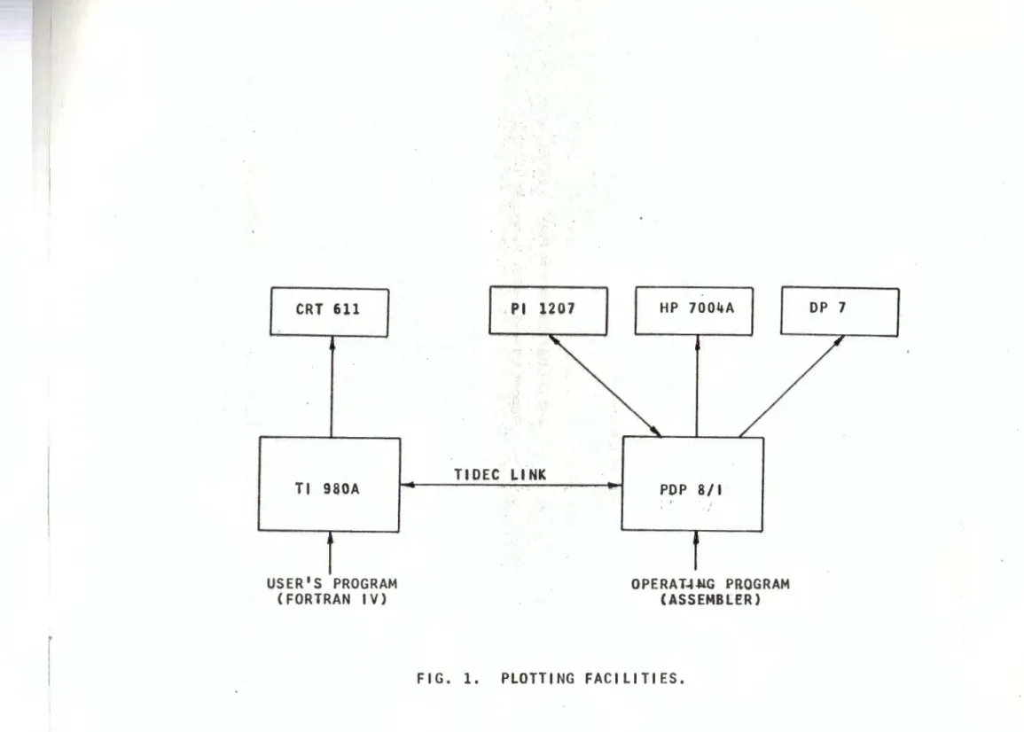
Plotting facilities available at M. D . S. L., and how they are linked together, are shown on Fig. l.
CRT is a Tektronix 611 Storage Cathode Ray Tube, with display area of 21 cm * 16.3 cm (x*y) .
HP-7004A is a Hewlett-Packard XY Plotter, with plotting area of 15 inch * 10 inch (x*y).
DP-7 is a Houston Instruments Drum Plotter with plotting area of 150 ft. maximum * 34. 5 inch (x*y), featuring three pens under program control.
4
I
J
J
J
J
J
J
J
I
_)_J
1~
j
PI-1207 is a Precision Instruments Read/Write , 7 track, Digital Magnetic Tape Recorder.
TI 980A is a Texas Instruments Computer System. PDP-8/1 is a Digital Equipment Computer System. TIDEC is a bidirectional data link connecting TI 980A with PD P-8/1.
This information is sufficient for an average user . An advanced user, who wants ,to operate the systems by himself, should consult the corresponding system and device manuals
listed as references in Chapter 8.
3. 0 USER'S SOFTWARE
All programming should be done in FORTRAN IV language, to be compiled, linked and executed on the TI 980A computer.
User's efforts should be concentrated on writing main programs doing his computations and calling the appropriate first level subroutines (Chapter 4. l) in the Plotting L ibrary. He might occa.sionally wish to write a first level subroutine not included there.
The standards for either of these tasks are described in Chapters 3. land 3.2.
3. l USER'S MAIN PROGRAM STANDARDS
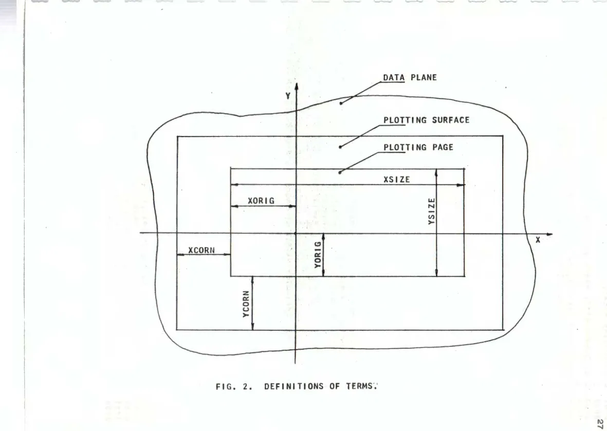
Let us define, with the help of Fig. 2, some terms common to all plotting devices :
PLOTTING SURFACE is the area within whtch the plotter can operate.
PLOTTING PAGE is a part of the plotting surfa ~.
5
-. ' i セ@ ,. 1 1
j
X CORNER and Y CORNER, in inches, specify the position of the plotting page within the plotting surface.
X SIZE and Y SIZE, in inches, specify the size of the plotting page.
DATA PLA.NE is the Cartesian plane in which programmer's data are defined.
X ORIGIN and Y ORIGIN, in inches, specify the position of the Data Plane origin within plotting page.
X SCALE and Y SCALE, in programmer's units/plotter's inch, specify data scaling.
Information on plotting page, data origin and scaling has to
I
be passed on to the plotting subroutines via two plotting parameters arrays, XPAR and YPAR, which should not be missing in the
calling program. They should be declared by the statement: DIMENSION XPAR(9), YPAR(9)
Preamble of each first level subroutine indicates which plotting parameters have to be assigned.
The programmer must always, in all plotting jobs, set XPAR(l) = XCORN
YPAR(l) = YCORN·
It is clear that the programmer must make sure that both XCORN and YCORN are positive, since the plotting page has to be within the plotting surface. Failure to' obey this rule causes job abort in the second level subroutine SPAGE, documented on they system's terminal •
Page size should also be declared in all plotting jobs: XPAR(2)
=
XSIZEYPAR(2)
=
YSIZE6
. _ _)
.J
J
J
J
.J
_J
J
I ;
_J 1 ll
1~l
! I ,It is obvious that both ><SIZE and YSIZE should be greater than zero, since a zero or negative page size doesn't make sense. Failure to obey this rule causes job abort in the second leve l subroutine SPAGE, documented on the system's terminal.
NOTE: Plotting page limits the plotting.
This feature of the Plotting Library, called "windowing", can be used to zoom on a particular area of the data plane • However, it can also produce blank plots.'
NOTE: There is no check within the Plotting Library to ensure that the plotting page is completely within the plotting surface, whichever device is envisioned for output. The programmer should make sure that both XCORN+XSIZE and YCORN+YSIZE are less than the corresponding dimensions of the plotting surface (hardware reasons~) and certainly not greater than lOOO. inches (software reasons~). Failure to obey these rules leads to plotting garbage or to job abort in the second level subroutine SPAGE, documented on the system's terminal.
Each plotting device writes with a pen, which has to be specified by setting:
XPAR(5)
=
PENPEN should have a single precision value with integer part equal l, 2 or 3, selecting pen_ A, B or C. Failure to obey this rule leads to selection of pen A.
NOTE: CRT 611 writes with electron beam as the "pen", and selection is ignored by the handware .
HP 70G4A has only one pen and selection is ignored by the hardware. The whole plotting job will be done in colour of the pen which is mounted in the pen hokier at that time .
7
-.;
DP-7 has three pens and the pen selection is honoured by the hardware. However, the plotting colours are determined by the colours of the pens mounted in the pen holders at that time.
The user should not be concerned with the pen up and pen down actions. The system takes care of them by itself.
In plotting jobs which require data scaling and offsetting the user must set :
XPAR(3) = XORIG YPAR(3)
=
YORIGThere are no restrictions here. Failure to set these parameters leads to unpredictable shifts of the data plane .
XPAR(4) = ><SCALE XPAR(4) = YSCALE
Both of these parameter~ should be greater than zero. (XSCALE=o. and YSCALE.=o . would leac:I to an infinitely large plotting data plane.) Failure to obey this rule causes j ob abort in all first level subroutines which scale data, documented on the system's terminal.
Any of the remaining parameters need to be assigned only when a subroutine is called which specifically requires them.
Here is the list of these optional parameters and names o f subroutines which use them :
XPAR(6) = free for all XPAR(7) = XPLCE in CHAR XPAR(8) = SPACE in CHAR XPAR(9)
=
TH ET A in CHARYPAR(5) = SYMBOL i n POINT YPAR(6)
=
SIZE in POINT YPAR(7)=
YPLCE in CHAR YPAR(8) = DOT in SCHAR YPAR(9)=
SIZE in CHAR- - -
J
I ..JJ
J
_j
_l
J
lJ
J
- j t _.,For details consult the descript ions o f the correspondi ng subroutines in Chaptet'II 4.
All plotting parameters preserve t he ir v a lues u ntil, explicitly c hanged by the calling program .
Besides by manipulating the plotting parameters to reach his plotting objective~, the user can program the selection o f the plotting link, request paper change and request end of plotting job.
Whenever the usei:- wants to direct his plott ing t o a spe cific plotting link he should do it with the statement:
CALL INIT(N)
I
where N is an integer variable not used anywhere else in t he program but in cal ls to INIT.
N = 0 selects TIO EC link.
.
N = l selects CRT 6ll .Default is TIDEC link. N wh i ch is neither O nor l is interpreted as request for TIDEC li nk .
The misuse of calls ·to INIT is rendered quite harmless . The system honours the last call to INIT before the plotting on
the selected device starts and then locks out all subsequent requests until a CALL PAGE requests paper charge or CRT screen erasure, when the last call to INIT before next plotting comes into effect .
NOTE: Device selection by software can be overruled by Sense Switches at run time. For details consult Chapter 6 . Whenever the user wants to change the plotti ng paper (or erase CRT screen) he should request it by i nc lud i n g a
CALL PAGE
statement where it is appropriate.
l
1
I
Il
Finally, the user should not forget to include a CALL PEND
statement before his STOP statement to ensure proper plotting job end and change of paper for the next user. Failure to obey _ this rule might result in an unfinished plot. It also inconveniences
the operator who has to restart the system manually.
PAGE and PEND are the only second level subroutines available to the user's main program. Use of other second
level subroutines in the main program might lead to plotting garbage or job abort.
3.2 USER'S SUBROUTINES STANDARDS
The user who wants to write his own first level subroutines is urged to study the library's first level subroutines in Chapter 4. l .
He wil l find there many useful procedures he could imitate or taylor to his needs.
He will also find that he should conform to ·certain standards in order to make the system perform properly.
All first level subroutines which explicitly call the second level subroutine PLOT to move the pen around must begin with the statement:
CALL S PAGE (XPAR, YPAR)
This is needed to establish page position and size as se lected by XPAR(l), YPAR(l), XPAR(2) and YPAR(2) . Failure to obey this rule m ight lead to plotting garbage or job abort~
All first level subroutines which explicitly use the scaling parameters XPAR(4) and YPAR(4) m~t check that they are greater than zero and take a corrective action if' necessary. Failure to do so might result in job abort due to divide by zero or to plotting garbage.
-" I
J
j
J
Third leve l subroutines should not be used in the first le v e l subroutines .'
Second and t h i rd leve l subroutines should not concern the user . Its creation and maintenance is th'? duty of the systems group.
4 . 0 PLOTTING LIBRARY
J
All programs in the Plotting Library are written as.J
J
J
J
subroutine programs .
They are placed at three levels.
The first level is occupied by subroutines of interest for an average user. They might communicate either directly or t hrough other first level subroutines with the second level subroutines~ but not with the third level subroutines.
The second level subroutines are only of interest to an
advanced user who wants to write his own first level subroutines. Only the subroutine PLOT, at the bottom of the second level, communicates with the third level subroutines, and then only with the highest one.
At the top of the third level is the subroutine DEVICE •
.
It uses the services of the· subroutine MTEST to recognize the selected device and turns contra l over to software interface TIDEC if Tidec Link has been selected or to software interface C RT if CRT 611 has been selected. These software interfaces, through the i r associated subroutines finally reach the phys ical devices and issue commands which make them act and pe rform .
Such partitioning i nto a grou p which is devi ce independent (first and second level) and a group wh ich is device depe nde nt
' '
A l
l
(third level) offers an opportunity for expansion by inclusion of additional plotting devices. Since the only tie between the two groups is from the subroutine PLOT to the subroutine DEVICE all what is necessary is to expand subroutine MTEST to recognize the new device, to expand subroutine DEVICE to direct the flow to the software interface of ~e new device, design this interface and associated subroutines to successfully drive that new addition to the system.
4. l FIRST LEVEL SUBROUTINES
The first level subroutines are well documented by their listings. Therefore, only a summary of their performance is given here. For details on use and operation consult tistings. For standards see · Chapter 3. 2.
Text handling subroutines :
PTEXT (NC,IC,XPAR,YPAR) plots a string of ASCII . characters.
I
NUMPLT (REALX, INTN, FORM,FIELD,DECIM,XPAR,YPAR) plots the formatted value of either a real or an integer variable. SSCHR (NC ,IC ,IS ,XPAR, YPAR) plots a coded character
string, with subscript and superscript capability.
SCHAR (NC, IC ,XPAR, YPAR) plots a coded character string. CHAR (CODE,XPAR,YPAR) draws a coded character.
Lines handling subroutines:
CIRCLE (RADIUS ,XCENTR, YCENTR ,XPAR, YPAR) draws a circle.
ARC (XFIRST, YFIRST ,XCENTR, YCENTR ,ALPHA ,XPAR, Y PAR) draws a circular arc.
_J
J
J
J
J
J
J
J
_J
J
.
..__,. j l ,,LGRID (XVAL,YVAL,XPAR,YPAR,IND) draws log-log and semi-log grids.
LXAXIS (XL,Yl,X2,XVAL,YTICK,XPAR,YPAR) draws a horizontal line with logarithmically spaced ticks .
L YAXIS (Xl, Yl, Y2, YVAL ,XTICK,XPAR, YPAR) draws a vertical line marked with loagrithmically spaced ticks . GRID (XINC,YINC,XPAR,YPAR,IND) draws linear grids. XAXIS (Xl,Yl,X2,XINCR, YT~CK ,XPAR,YPAR) draws a horizontal line marked with linearily sl?aced ticks .
YAXIS (Xl, Yl, Y2, YINCR ,XTICK,XPAR, YPAR) draws a vertical line marked with linearily spaced ticks .
POINT (XAR,YAR,NP,XPAR ,YPAR) plots an array of points marked with a symbol.
LINE (XAR,YAR,NP,XPAR,YPAR) conr:iects an array of points with straight lines.
OLINE (XAR,YAR,NP,XPAR,YPAR,DASH,BLANK) connects an al"ray of points with dashed lines.
Utility subroutines:
SCALEP (ARRAY,LARRAY,SIZE,PSCALE,FLOOR,ORIGIN) finds an appl"opriate scale and position of a data array within the plotting page.
SCALE (ESCL,PSCL) computes and adjusts plotting scales . 4.2 SECOND LEVEL SUBROUTINES
The fil"st two subroutines service the first level text handling subroutines:
CHRGET (CODE,COUNT ,MATRIX) gets data matl"ix of a coded character.
READ (MX) moves chal"acter set data from the disk into memory .
13
Next come service and data handling subroutines:
SPAGE (X~AR,YPAR) sets page position and size. PUP lifts _all pens up.
PDOWN (PEN) puts down selected pen. PAG_E requests paper change.
PEND ends plotting job.
All these subroutines merely translate names into code numbers of the subroutine PLOT which, being the heart of the second level subroutines, deserves special attention.
Subroutine PLOT (X, Y, N) pr<:vides bookkeeping and
processing services. It initializes default values, keeps track of page position and size and current pen location, services pen action requests, paper change request, plotting end request and resets pa~ position and size when asked to do so. When it accepts the coordinates of the new pen position, which should be
in inches referenced to the lower left corner of the plotting page, it imposes page "window" on the data, computes new data, in
\
inches referenced to the lower left corner of the plotting surface, and reconsiders pen actions. PLOT communicates only with the top third level subroutine DEVICE for routing to the selected device.
Glossary of variables in subroutine PLOT and flow charts supplement the reading of the listing.
N X,Y FIRST \
XCRN,YCRN
Service code
Point or page arguments . First call index; zero at loading time.
Defa~lt values of XCORN, YCORN; both zero at loading time.
J
j
J
J
J
_J
J
J
J
_l .
j
" ) XSZE,YSZE XCORN, YCORN XSIZE, YSIZEXMIN, YMIN ,XMAX, YMAX
XOLD,YOLD XNEW,YNEW XNEWP,YNEWP M PENM PENS PENG INSW BACK
Default values of XSIZE, YSIZE : 15 inch, 10 inch at loading time. Coordinates, in inches, or the lower left corner of the plotting page, referenced to the lower left corner of the plotting -surface. Plotting page size in i nches .
Coordinates of the plotting page corners' in inches' referenced to the lower left corner of the plotting surface.
Coordinates of the old move request, in inches, referenced to the lower left corner of the plotting surface.
Coordinates of the new move request, in inches, referenced to the lower left corner of the plotting surface.
Coordinates of the actual new pen position, in inches,
referenced to the lower left corner of the plotting surface. Service code
Pen mode request. Pen status .
Pen command .
Point's inside/outside s witch . Link between inte rsection and plotting routines.
/ NRSEC NSEC XSl, YSl XS2,YS2 DX,DY DXl,DYl DX2,DY2 DX3,DY3 AL ALl ALP XI,ETA KEY
4.3 THIRD LEVEL SUBROUTINES
Number of intersections of the segment with the page boundaries.
Number of intersections of the segment with the page boun9aries.
Coordinates of an intersection. Coordinates of an intersection. Segment components.
Distance to boundary component. Distance to boundary component. Distance to boundary component . Segment parameter ).
Segment parameter セ@ i
). I
Segment parameter /\.
Intersection coordinates
5,
i
Internal link in the intersection routine.The third level subroutines, which deal directly with the
'
available plotting devices., begin with the subroutines DEVICE and MTEST.
DEVICE (X, Y ,M) calls upon MTEST(N) to find out which is the current plotting device in operation and then passes the
arguments X, Y .,M received from ~he last second level subroutine PLOT to the appropriate head subroutine of the current device. At present time there are two head subroutines, namely TIDEC and CRT.
(
J
J
]
_J
j
J
J
J
. JMTEST(N) is a multiple entry assembler subroutine . Entry !NIT selects the device when called with the statement CALL INIT(N) in the calling program . N=Q or N neither O or l selects TIDEC, while N=l selects CRT. Omission to call !NIT results in TIDEC selection.
Entry MTEST polls the current status and returns N=Q for TIDEC or N=l for CRT being currently i n operation. It also polls Sense Switches to see if the operator did overrule software of default device selection.
Entry MTESTP is entered only from either the subroutine TIO EC or subroutine CRT, and then only when paper change was requested.
Entry MTESTE is entered only from either the subroutine TIDEC or subroutine CRT, and then only whe·n end plotting job was requested.
Both of those entries reset subroutine MTEST
appropriately and, in case of CRT being in operation, wait for the operator to flip Sense Switch 4 up and down to erase the screen and return to calling program. Glossary of variables in subroutine MTEST:
FIRST Usage indicator: 0 for MTEST being entered first time, l for being already called. It is zero at loading time .
SMODE Software selection indicator : 0 fo r TIO EC being selected by software , l fo r C RT being selected by software . It is z e ro- at load ing time .
MODE Current operation indicator: 0 for TIDEC currently in operation, l for CRT currently in operation.
4.3. l TIDEC LINK SUBROUTINES
Now fol lows a group of subroutines, headed by TIO EC, which translate numerical data into output data intended for the devices serviced by PD P-8/l through Tidec Link.
TIDEC(X,Y ,M) receives its arguments from DEVICE which obtained them from PLOT. It has the task to encode them according to certain rules and accumulate them into an 800 bytes (=400 words) buffer !BUFF . This buffer is sent through Tidec Link to PDP-8/l for acceptance and dispatch to the operator selected device, either when
it is full or when change paper or end job is requested. Actions pens up, pen A down, pen B down, pen C down, ·
change paper, signalled by the values of M=6, l,2,3, or 5 cause one ASCII byte U,A,B,C or P to enter !BUFF.
M=4 requests the pen to move to position (X, Y), in inches referenced to the lower left corner of the plotting surface. Values (X, Y) are rounded off to O. 001 inch, fixed into two 24 bit integer, packed into three 16 bit words, encoded into ASCII characters, prefixed with ASCII character M and entered, as 13 bytes, into IB UFF.
M'=6 requests end of plotting job. The appropriate
signal is sent directly to PDP-8/I, without entering !BUFF.
Since some of these operations would be inefficient in FORTRAN, if not downright impossible (buffer transfer, end of file action) . four assembler subroutines execute the m:
1111
I
,.IJ
J
J
J
J
.J
_J
J
J
IUI}I
- - - · - ~·--- - - -~- - ·-.MASCH (NXY ,!CHAR) does prefixing with ASCII character M and encodes NXY into 12 ASCII characters.
PCHAR (JBYTE,IBUFF(JBUFF),ICHAR(JCHAR)) takes care of filling !BUFF with ASCII bytes.
MBUFF (!BUFF) moves the buffer !BUFF to PDP-8/{ by issuing commands to Tidec Link Device Service Routine, which is a part of the System.
EOF33 issues an End of File command to Tidec Link Device Service Routine, which informs PD~8;t of end of job. For details on Tidec Link and Tidec Link Device Service Routine consult Reference 2.
For details on the role of PDP-8/I in the plotting process consult Reference 3.
4.3.2 CRT SUBROUTINES
' Now follows a group of subroutines, headed by CRT, which translate numerical data into output data for Tektronix 6lf Storage Cathode Ray Tube.
CRT (X, Y ,M) receives its arguments from the subroutine PLOT through the subroutine DEVICE, if CRT operation was selected. Again, as in PLOT, the action depends on the value of the argument M:
M
=
0 turns the beam off. M = 1,2 or 3 turns the beam on. M = 4 executes beam motion.M = 5 erases the screen and restarts. M
=
6 erases the screen and ends job. For more details consult listing of CRT.Subrouti ne CRT uses the services of·assembler subroutines INCRT, ONOFF, MOVE! AND VCTRI to output data and commands to the Cathode Ray Tube.
INCRT ONOFF MOVE! (NX,NY) VCTRI (NXl, NYl, NX2,NY2)
erases the screen. turns the beam on/off.
forces the beam into the point (NX,NY).
moves the beam from (NXl, NYl) to (NX2, NY2). For more details on CRT link consult References 4 and 5. 4.3.3 SUBROUTINES SYSKEY AND RFF
In a subroutines programs package, like the here reported
I
Plotting Library, the need often arises to check for error conditions, signal them to the operator and either wait for his corrective action or abort job.
Since it was not advisable to set aside a Logical Unit Number permanently assigned to the system's terminal (KEY), an assembler subroutine SYSKEY has been written which, when used properly, communicates with KEY from a FORTRAN program directly.
SYS KEY is not a part of the Plotting Library. It is inserted into the FORTRAN Library in front of the subroutine FFEDIT and thus it is available to any FORTRAN program in general.
For details consult listing of the subroutine SYS KEY .
Formatted input from the keyboard is inconvenient since the operator has to know the input format. To avoid this awkward constraint a subroutine RFF (for ~ead _free _format) has been written • Calls to this subroutine, instead of READ (m, n)
statements, allows the operator to input numbers in free format, using commas field delimiters.
l
J
J
j
J
1
J
!o
I
- - - ~·- - - ---RFF is not a part of the Plotting Library. It is inserted into the FORTRAN Library in front of the subroutine FFEDIT and thus it is available to any FORTRAN program in general.
For details consult listing of the subroutine RFF .
5.0 CHARACTER SET
The common way of composing a character picture is by means of straight line strokes between nodal points of a matrix grid. E;xecution is fast but the quality of the characters is poor. Ang1,.Jlar shape becomes prominent at large scales. Low case, greek or special characters look funny.
Therefore, in this Library, it was decided to trade speed for quality and compose a character out of straight lines and circular arcs. This way the shape and quality of a character becomes independent of the scale, provided that the quality of plotting circular arcs is also independent of the scale .
There is a basic matrix of 12*12 matrix units but it only serves to fix the reference system for the points. Coordinates of the points are given in matrix units referenced to the lower
left corner of the character matrix. Note that the coordinates of the points could assume any values and not only discrete i nteger nodal values, positive and within matrix boundaries.
Once a character has been designed and approved it is assigned a unique code number. Character data comprise code number, pen actions, line elements and circular arc elements.
Character codes are not assigned haphazardly. Where possible they correspond to the stripped ASCII codes.
All characters together form a character set.
Currently there is ·room for 150 characters in this set.
- - -
·-·---Codes l through 90 are assigned to ASCII characters (with small circle for period), code 91 is assigned to a dot as period, code 92 draws Canadian Logo, character codes
101 through 133 are used f'.or geek letters. Other code numbers are currently assigned to the ASCII space, but can be reassigned as the need for other characters arises.
Character data are punched on cards in format (A2, SX,
First card for each character defines its code number (prefix N), other cards define pen action up (prefix U), pen action down (prefix D), line elements (prefix L, followed by coordinates X, Y of the ending point) and arc elements (prefix A, followed by coordinates XC, YC of the arc center and central angle alpha in degrees). Last card of each character data is *
in the first column. Last card of the whole set is/ in the first column.
Listing of the whole character set and characters' appearance and code numbers are appended to this Chapter.
'
'The character set is stored on Disk l, cartridge SYSVOL 000001, under file name CHRSET.
The program which does the storing is named , CED IT . It also encodes character data into binary integer strings, packs them together in an integer array MX and stores th~t array, when all is gone through error free, on disk file CHRSET.
This _9haracter Editor is useful at the designing stage o f a new character. Of course, a temporary disk file shou ld then be used , otherwise the file CHRSET would be obliterated.
For more details consult listing of CEDIT.
1
.. 1
JJ
J
1
J
{
..I
6.0 PLOTTING OPERATIONSThe content of this chapter is of interest only for the system's operator or for the knowledgeable user who wants to execute his programs by himself.
Plotting Library resides on the Disk l, cartridge SYSVOL 000001, under file name PL TLIB.
Assume that the program to be executed is com pi led and linked with job library PL TLIB and FORTRAN Library FTNLIB into file GO.
The operator sets up the device on which the output has to appear and initiates the job by typing into terminal:
//ASSIGN, 7 ,MHDl,CHRSET. //ASSIGN,30, D/A. //ASSIGN,31,CM • //ASSIGN,32,CRT. //ASSIGN,33, TD. //ASSIGN, BO, .••••.
.
.
.
.
.
.
.
.
. .
.
.
.
.
.
.
.
.
. .
//ASSIGN, 87 ••••••. //EXECUTE,MHDl, GO,For text output. For CRT Link. For CRT Link. For CRT Link. For TIDEC Link.
As required by the program •
The output will flow to the device selected by software (see Chapter 3. l) or enforced by Sense Switches:
Sense Switches: l 2 3 4
Software Mode down down down down TIDEC Link ~nforced up down down down CRT Link enforced down tl1h Ji". down down
Other switch settirigs are illegal and if they happen the operator ge~ a message to take corrective action .
·
- - - -
---CRT operation, whether set up by software or enforced by. Sense Switches, reacts to the paper change or end job requests by instructing the operator to flip Sense Switch 4 up and down. This erases the screen before proceeding.
The operator will have to answer various questions to the terminal or to obey some instructions. There is no need to enumerate them here explicitly. They are kept as clear and unambigous as possible and improper actions or answers are rejected.
If in doubt the operator should consult listings and referenced reports.
7. 0 EXAMPLES
Program TEST OLINE shows how to produce dashed lines . Program TEST NUMPLT' shows how to plot formatted integer or single precision variables.
Program TEST PTEXT _shows how to plot text strings.
Program PENTST shows how to adjust pens on DP-7 plotter.
'-Program CHRPL Twas used to plot character set for this report.
J
J
JJ
{
1
---
--- -... --8.0 REFERENCES l. TI 980A Manuals:Basic System and Operation. Machine Code Instructions. Assembler Code Conventions. Assembler Input/Output.
FORTRAN Arithmetic.
FORTRAN Declarations' and Input/Output.
FORTRAN Library.
PDP-8/l Manuals:
Small Cbmputers Handbook. Introduction to Programming. Programming Languages.
2. D. Gospodneti6 : "Link between Texas Instruments 980A
and Digital Equipment PD .P-8/l Computers .",
Report L TR-SH-153, February 1974.
3 . M. D. Miles : ":Interface of Houston Instruments DP-7 Drum Plotter to a PDP-8 Computer and Basic Software Plotting Package. ", Report L TR-SH-152, July 1974.
4 . D . Gospodnetic : "Binary Command Module in TI 980A Computer System . ", Report MTB-95, June 1973.
5 . M.D. Mites : "CRT PLOT - A FORTRAN Plotting Package fol"' the Tektronix 611 Storage Tube on the MOS L TI 980A Computer System ." , Report MTB-96, June 1973.
0
25
,l;.4..,t..:...,"-~ .. ,.:J.;;i,.~.~~ ..
CRT 611 Pl 1207 HP 7004A
TIDEC l-lNK
Tl 9SOA POP 8/ I
USER'S PROGRAM OPERAT~~G PROGRAM
(FORTRAN IV) (ASSEMBLER)
FIG. 1. PLOTTING FACILITIES.
DP 7
I\)
O>
Mi XCORN XORIG z 0::: 0 u > y CJ
-0::: 0 > L....----· L-._... ,._____,. :..._____ セ@ DATA PLANE PLOTTING SURFACE PLOTTING PAGE XSIZE UJ N (/)>-FIG. 2. DEFINITIONS OF TERMS;
1
~ . セ@
X ,
I\)
000 1 C 0 0 ~2 C 0 0 03 C 0 0 04 C 0 0 ~5 C 0 0 06 C 0007 C 0 0 08 C 0 0 09 C 0010 C 0 0 11 C 0012 C 001~ C 0 CI! 14 C 0015 C 0016 C 0017 C 0018 C 0019 C 0020 C 0021 C 0022 C 0023 C 0024 C 0025 C 0026 C 0027 C 0028 C 0029 C 0030 C 0031 C 0032 C ij033 C 0034 C ~03~ C 0035 C 0037 C 0038 C 00JQ C 0040 C 0041 C 0042 C ki043 C 0044 C 0045 C 011)48 C 0047 C 0048 C 004g C 00,0 C 0051 C 0052 00 !5:5 00!54 005S 0056 SUBROUTINE PTEXT.
D. GOSPOO NETIC, MARCH 24, 1974.
SUBROUTINE PTEXT PLOTS A STRING OF NC CHARACTERS STORED I N THE ARRAY IC AS ASCII CHARACTERS, PACKED 1 CHARACTER PER ~ORO. "COMMERCIAL AT" (') CHARACTER IS NONPRINTABLE.
IT SERVES LIKE A SHIFT KEV ON THE KEYBOARDS
AFTER A SINGLE I IS ENCOUNTERED TH! "KEYBOARD" SHIFTS TO
UPPER CASE CHARACTERS.
AFTER TWO CONSECUTlVE f ARE ENCOUNTERED THE "KEYBOARD" SHIFTS
TO LOWER CASE CHARACTERS (ONLY ALPHABET A . , Z IS ACCEPTED)• "NO." (#) CHARACTER IS NONPRINTABLE.
IT SERVES LIKE THE UNDERSCORE KEY ON TH! KEVBOARDz
28
"KEYBOARD« UNDERSCORES THOSE PARTS OF THE STRING ~H?CH ARE ENCL OSE D BETWEEN TWO# CHARACTERS.
DEFAU LT AT LOADING TI ME IS SHIFT TO UPPER CASE CHARACTERS ANO NO UNDERSCORES. PLOTTING PARAMETERS& XPAR(l)•XCORN XPAR(2)•XSIZE XPAR(5)aPEN NUMBER XPAR(7)!1XP1.CE XPAR(8)1SPACE XPAR(9l•THETA YPARC1)•YCORN YPARC2l•YS1ZE VPAR
en
•YPI.C! YPARC8)•DOT YPARC9)•SIZEXPLCE,YPLCE ARE T~E COORDINATES ,Q, THE LOWER LE~T COAMER OF , THE FlRST CHARACTER HATR?X IN INCHES REFERENCED TO THE LOWER LEF T COR NER OF TH! PLOTTING PAGE.
THETA
IS
ANGULAR ORIENTATION IN DEGREES OF THE CHARACTER STRI NGc COUNTERCLOCKWISE IS POSITIVE.SIZE IS THE HEIGHT OF CHARACTERS IN INCHES. CHARACTER MATRIX IS S!ZE•S?ZE IN INCHES. SPA.CE IS SPACE IN INCHES BETWEEN MATRICES. SPACE•0• IS NOR MALLY USED.
OOT•0. FOR A DOT, OOT•1. FOR A SMALL CIRCLE AS PERIOD.
TMIS SUBROUTI ~! NEEDS ASSIGNM!NTI
//ASSIGN,1,~H01,CHRSET. . SUBROUTINES USEOI SCHAR,LINE.
SUBROUTINE PTEXT(NC,IC,XPAR,YPAR)
DIMENSION 1CC1),XPARC1),YPAR(1),%?C(80),XP(e),YP(4),XC2),YC2)
INTEGER SHIFT,SFLAG,COOE,UFLAG OATA SHIFT/0/,SFLAG/0/,UFLAG/0/
J
J
1
J
Jj
J
I _
j
I ' . ]I
0057 0058 0059 0050 0061 00$2 ·012163 0064 0065 0066 0057 0068 ~069 0070 012171 "072 0073 1407 400,e
0076 0077 0078 121~79 0080 0081 0082 0083 0084 !008!5 008ts 0087 0088 00ag 0090 0091 Hlg2 00S)3 0094 0095 0096 0097 0098 0099 0100 0101 0102 0103 0104 0105 0105 0107 01'48 0109 0110 ~111 0112 CC UNPACK ASCII ARRAY AN D FORM COOE ARRAY,
L.•0 C L.1•'11 00 hi J ·•1,NC CODE•ICCJ) IF(CODE.GE.0) GO TO 1 COOE•COOE+32767 1 COOE•COOE/2~6 IFCCCOOE.GE.32).AND.CCbDE.L.E.96)) GO TO 2 COOE•32 2 CODE•MOD(COOE,64) IFCCOOE.NE.0) GO TO !5 GO TOC3,4,3), SFL.AG+1 3 SFl.AG•1 SMIFT•0 GO TO 10 4 SFL.AG•2 SHIFT•64 GO TO 10 !5 SFL,AQ,0 COOE•CODE+SHIFT lFCCODE.L.E,90) GO TO 6 COOE1132 6 IFCCOOE,NE,3~l GO TO g IFCU~l.AG,!Q,1) GO TO 7 L.1 •L. UF1.AG•1 GO TO 10 7 L.2•L. UFL.AG•0 IFCL.2.L.E,Lll GO TO 10 8 XPC1)•XPAR(1) YP C1) •YPAR C1) XP (2) •XPAR (2) YP(2)•VPAR(2) XP
ce)
•XPAij C~) SPAC!•XPA~(8) T~ETA•XPAR(g)•0,0174533 SIZE•YPAR(9) SINT•SIN(THETA) COST•COS(THETA) OCHAR•SIZE•SPACE USCORE11SIZEl6. XPLCE•XPAR(7)+USCORE•SINT YPLCE•YPAR(7)•USCORE•COST AL1•L1'*'DCHAR AL2•L2•0CHAR•SPACE XC1)•AL1•COST+XPLCE YCl)•ALl•SINT+YPLCE XC2)•AL2•C0ST+XPL.CE YC2)•AL2•SINT+YPLCE CALL LINECX,Y,2,XP,YPl IFCUFLAG.EQ.1) GO TO 11 GO TO 10 29011~ 0114 011:S 0116 0117 0118 0119 0120 0121 9 L.•1.+1 ItCCl.)•COOE 10 CONTINUE IFCUFLAG.EQ.0) GO TO 11 1.2•L IF(L2.GT.L1) GO TO 8 11 C•LI. SCHARCL,IIC,XPAR,VPAR) RETURN ENO SU6ROUTINE
SF4GSU MOO SF4CGT SIN
cos
$F4RET SF4STP
PROGRAM ALLOC.ATION
000C'l SHIFT 00~1 SFLAG 0002 UFI.AG 0005 J 0006 CODE 0007 L2
000C SIZE ~00! SINT 0010 COST 0016 XPLCE 0016 YPI.CE 001A AL1
001E IIC 006E XP 0078 't'P
30
SF4IRC t.INE SCHAR
0003 L 000"4 L1
0008 SPACE 000A THETA
0012 OCHAR 0014 USCORE
001c AL2
l
J
l
J
Jl
j
I
0~01 0002 0003 0004 000~ 0006 0007 00~8 0009 ~010 0011 ~012 0013 00141 0015 0016 0017 0018 0019 0020 0021 0022 0023 0024 002!5 0026 0027 0028 0029 0030 la031 0032 0033 0034 003!5 0036 0037 0038 0039 004~ 0041 121042 0043 0~44 0045 004e 0047 0048 0049 0050 0051 0052 0053 0054 00~5 0056 C SUBROUTINE NUMPLT. C 31 CD. GOSPOONETIC, FEBRUARV 14, 1914. C C C C C C C C C C C C C C C CSUBROUTINE NUMPLT PLOTS THE FOR~ATTEO VALUE OF EITHER A REAL OR AN INTEGER VARIABLE.
FOR~ATT!NG !S OONE ACCORDING TO FORTRAN RULES.
TO PLOT THE INTEOER VARIABLE INTN IN I FORMAT SPECIFY FORM•0 AN O FIELD• FIELD LENGTH IN CHARACTERS.
TO PLOT A SINGLE PRECISION REAi. VARIABLE REALX INF ORE FORMAT SPECIFY FORM•1 OR 2, FIELO•FIELD LENGTH IN CHARACTERS ANO OECIM• NUMBEH OF DECIMAL PLACES.
REALX IS ROUNDED OFF BEFORE PLOTTING, FORM, FIELD ANO OECIM ARE INTEGERS,
C ERROR CONDITIONS ANO CORRESPONDING ACTIONSI
C FIELD LENGTH LESS THAN 11 ONE ASTERISK IS PLOTTED.
C FIELD LENGTH GREATER THAN 20S TWENTY ASTERISKS ARE PLOTTED, C FORMAT ~UALIFIER NOT 0, 1 QR 2, OR NUMBER OF DECIMALS NEGATIVE, C OR FIELD LENGTH TO SHORTI FIELD OF ASTERISKS IS PLOTTED.
C C C C C C C C C C C C C C C C C C C C C C C C C C C PLOTTING PARAMETERS& XFIARC1)•XCORN XPAR(2)•XSIZE XPAR(S)aPEN NUMBER XPAR (1) 11XPI.CE XPAR(8)•SPACE XPAR(9)•THETA YPAR(1)•YCORN YPARC2l•YS1ZE YPAR(7)•VPLCE YPAR(8)11DOT YPAR(9),stze:
XPLCE,YPI.CE ARE THE COORDINATES OF THE LOWER LEFT CORNER OF TME FIELD IN INCHES REFERENCED TO THE LOWER LEFT CORNER
OF THE PLOTTING PAGE,
THETA IS ANGULAR ORIENTATION IN DEGREES OF TH! CHARACTER STRI NG~ COU~TERCLOCKWISE IS POSITIVE.
SIZE IS T~E HEIGHT OF CHARACTERS IN INCHES. CHARACTER MATRIX IS SllE•SIZE INCHES.
SPACE IS SPACE IN INCHES BETWEEN MATRICES. SPACE•0. IS NORMALLY USED.
OOT•0. FOR A OCT, OOT•l. FOR A SMALL CIRCLE AS PERIOD. THIS SUBROUTINE NEEDS ASSIGNMENT&
//ASSIGN,7,MH01,CHRSET. SUBROUTINES USED: SCHAR.
SUBROUTINE NUMPLTCREALX,INTN,,ORM,FI!LD,DfCIM,XPAR,YPAR) DIMENSION XPARC1l,YPAR(1),CHAR(20) 1TEMP(20)
INTEGER ~ORM,FIELO,DECIM,CHAR,T!MP INTEGER E,SPACE,STAR,PLUS,PERIOD,ZERO
1(1057 0058 005g 0060 0 061 0062 0053 0 0 64 0065 006B 0067 0068 0069 0070 ~071 0072 0073 0074 0075 0076 0077 0078 007g 0080 0081 0082 0083 0084 '108!5 0086 0087 0088 0089 0090 00fi1 0092 0093 0094 0095 00ge 0097 0298 0099 0100 0101 01162 0103 0104 010!5 0106 0107 0108 010g 0110 0111 0112 , I C
C CHECK FIELD LENGTH. セ@
NF;sFIEI.O
IFCCNF.LT.1).0R.C NF.GT.20)) GO TO 35
C CHECK FORMAT QUAI.IFIER.
IFCCFORM.LT.0).0R.(FO~M.GT.2)) GO TO 35
C FIi.i. FIEL.0 WITM SPACES.
00 1 J•lll,NF CHARCJ)11SPACE 1 CONTINUE C GO TO APPROPRI4TE ROUTINE. GO TO (2,10,2,), FORM+l C C C FORMAT(! FIEL.D) 2 L•0 N•lNTN IFCN) 4,3,!5 3 I•NF CHARCI)•ZERO GO TO 35 4 NW•N L.•L•1 TEMPCL)•MIN US !5 M•10000 6 NC•NIM lFCNC.NE.0) GO TO 7 MaM/10 GO TO 5 7 L•l.+1 TEMP CL) •ZERO+NC . IF(M.EQ.1) GO TO 8 Nllll•NC•M M•M/10 NC•N/14 GO TO 7 8 I•Nf'•L
C FIELD I.ONG ENOUGH?
IFCI.LT.0) GO TO 36 00 g J•1,L I•I+1 CHAR(I)•TEMPCJ) g CONTHtUE GO TO 3!5 C C C FO~MATCF FlELD.DECIM) 10 ND•OECIM
C NUMBER OF DECIMALS LESS T~AN ZERO? IFCNO.LT,0) GO TO 36
I OIF•N0•2
C MINIMUM · ,tELO L!NGTH?
IFCI.LT.0l GO TO 38 I•I+1
CHAR CI) •Z!RO
I•I+l
0113 CHAR(I)•P ERIOO 33 0114 L.. 0 011~ X•REALX
J
0116 IF(X) 12,35,14 0117 12 X••X 0118 L.•L+ 1 0119 iEMPCL)•ti'IINUS_] 0120 ~121 C C SUBRO UTINE TO NORMALIZE
x.
0122 14 K•0
J
0123 15 IFCX.GE.1.l GO TO 16 la124 X•X•10 0125 !<•K•1- J
0126 1.1121 16 IFCX.LT.1.) GO TO 17 GO TO 15 0 128 )(aX/10, 0129 K•t<+1 . J 0130 GO TO 16 0131 . 1 7 IFCFORM.ECJ.2) GO TO 29 0132 C-. l
0133 0134 Ni:ht<+N0+1 IFCNR.L.E.0) GO TO 1g ~135 XtX+~/(10.••NR) 0136 IFCX,L.T.1.) GO TO 19i.
0137 0138 X•X/10, K•K+l 0139 19 IFCK,GT,0) GO TO 20 J 0140 L.•L.•1 0141 TEMP(L)•ZERO 0142 GO TO 21 0143 20 X•X•10, 0144 NC•X 014e X•X•NC 0146 L.•L.+1 0141 TEMPCL.)wZERO•NC 0148 K•K•1 0149 IF(l<,CiT,0) GO TO 20 0150 21 I• I'"L.• 10151 C FIELD LONG ENOUGH?
0152 IFCI,LT,0)
Go · ro
36 015:5 DO 22 J•1,L. 0154 1•1+1 0155 C~AR(I)•TEMP(J) 0156 22 CONTINUE 01:S7 IFCNO.EQ, 0 ) GO TOJe
0158 IFCl<,EQ,0) GO TO 231u:s;
I(. •I<01150 X•X/(10,••Kl ia 1 tH 23 I•I+t 0162 00 24 J111,ND 0163 )(!1)(•10, 0164 NC•X 01ee X•X•NC 0166 I11I+l 01e, CHARCI)•Z!:RO+ NC 0168 24 CONTINUE
0169 0170 0171 0172 0173 0174 0175 017tJ 0177 0178 0179 0180 liJ 181 0182 1Uo3 0184 018~ 0186 rdl 87 0168 0189 01Sl0 f41 Y 1 01Q2 0193 0194 IH90 0196 0197 0198 0199 0200 0201 0202 0203; 0204, 0205 02fdl5 ld207 0208 0209 0210 0211 0212 0213 0214 021!5 02US 0217 0218 0219 0220 ta22t 0222 0223 0224 GO TO 35 C C C FORMAT(E FitLD.DECIM) 25 NO•OECIM
C NUMBER OF OECIMAI.S LESS THA~ ZERO?
lF(NO.LT.0) · GO TO 36
l=HIF•N0•7
C MINIMUM FIELD LENGTH?
C C IFCI,LT,0) GO TO 36 l•I+2 Cl'IAR(I)•ZERO ?111 I+ 1 Cl-4ARCI)•PERIOO l.•0 X•REAI..X
1,cxJ
21,35,2e 27 )C••X L.•L.•1 TEMP(L)tMINUS GO TO 14 28 L•L+1 TEMPCL)•SPACE GO TO 14 29 l.•1.+1 TEMPCL)•ZERO l.•L+1 TEMP Cl.) •P!fUOO N~aN0•1 X•X•51 (Ul.••NR) I~CX.LT,1.) GO TO 30 Xl)(/10, K•K•1 30 IFCNO,EQ,0) GO TO 31 x,x•10. NC•X X•X•NC L•L.+1 TEMPCL)•ZERO•NC ND•N0•1 GO TO 30 31 l.•1.+1 TEMP CLl •E IFCK,L.T,0l GO TO 32 I. •I.+ 1 TEMPCL)•PLUS fiO TO 33 32 l.•L.+1 TEMP(L.)aMINUS K••I< :S3 NC11<110 L•L.+1 TEMP(L)•ZERO+NC NC•l<•NC•10 34·J
}
J
. J.J
_l.J
J
.
) IJ
C C L.:aL.•1 TEMP CL) azERO•HJC I•I•3 00 34 J•1,I. I• I+ 1 CMAR(I):aTEMP(J) 34' CONTINUE . CPL.OT NUMBER. 35 CAL.L SCHA?CNF,CHAR,XPAR,YPAR) RETURN C C 0225 0226 0221 0228 0229 0230 111231 0232 0233 0234 0235 0236 0237 0238 02Jg 0240 0241 0242 0243 0244 0245 0246 0247 0248C ERRORS. FIL.L FIEL.0 WITH ASTERISKS ANO PLOT. 36 IFCNF.LT.1) NF•1 IFCNF.GT.20) NF•2 0 DO 37 Jal,NF CHAR(J)•STAR 37 CONTINUE GO TO 3~ C C END SUBROUTINE
SF4GSU SF4CGT $F4IRC SF4RIP
PROGRAM ALL.OCATION 0000 E 0001 SPACE 0002 000~ PERICO 0006 ZERO 0007 000A. N 000B I 000C 000F )( 0 011 I< 0012 0013 CHAR 0027 TEMP
SF4RIC SCHAR SF4RET
STAR 0003 PLUS 0004
NF
1008 J 0009 M la00D NC 000E NR 35 SF45TP MINUS L NO- - - -- -·- - - - -- - -
- - - - -- - - - -- - - -.,0001 0002 0003 0004 000~ 0006 0007 0008 0009 0010 0011 0012 0013 0014 001!5 0016 0017 0018 0019 0020 0021 0022 0023 0024 002!5 0026 0027 0028. 0"29 0030 0031 0032 0033 0034 0035 0036 0037 0038 0039 0040 0041 0042 0043 0044 004~ 0046 0041 0048 0049 0050 00151 0052 0053 0054 005!5 0056 C SUBROUTINE SSCHR. 36 C C C C C C C C C C C C
c.
PROGRAM~ED BY M.D. MILESSSCMR IS A SUBROUTINE WHICH PLOTS CHARACTER STRINCS BY CODE NO. WI TH THE CAPABILITY TO HANDLE SUBSCRIPTS ANO SUPERSCRIPTS.
INTEGER ARRAY IC REP~ESENTS THE STRING OF CHARACT~RS BY CODE NUMBE RS. INTEGER ARRAY IS SPECIFIES CHARACTER TYPE.
IS(J) • •1 IF ICCJ) IS TO BE A SUBSCRIPT. IS(J) • 0 IF lCCJ) IS A NORMAL CHARACTER.
1SCJ) • +1 IF IC(J) IS TO BE A SUPERSCRIPT.
C NOTE~ SUB
&
SUPER•SCRIPTS ARE PLOTTED AT 3/4 THE SIZE SP!CIFIED FOR C THE NORMAL CHARACTERS ANO ACCORDINGLY ARE SPACED OUT AT 3/4 C OF THE NORMAL CHARACTER SPACING.C C C C C C C C C C C C C C C C C C C C C C C C C C C PLOTTING PARAMETERS: XPAR(1)•XCORN XPARC2)•XSIZE XPARC5)1P!N NUMBER XPAR(7)•XPLCE XPAR.(8)•SPACE XPAR(9)•TMETA YPAR 0) •YCORN YPARC2)•YSIZE YPARC7l•YPLCE YPARC8)•DOT YPAR(g)•SIZE
XPLC~,YPLCE ARE T~E COORDINAT!S OF THE LOWER LEFT CORNER OF TH E FIRST CHARACTER MATRIX IN tNCH!S REFERENCED TO THE LOWER LEFT CORNER OF THE P~OTTING PAGE.
THETA IS ANGULAR ORIENTATION IN OiGREES OF TH! CHARACTER STRIN G0
COUNTERCLOCKWISE IS POSITIVE,
StZE IS THE HEIGHT OF CHARACTERS IN INCHES, CHARACTER MATRIX IS S?ZE•SIZE IN INCHES. SPACE IS SPACE IN INCHES BETWEEN MATRICES. SPACE•0. IS NORMALLY USED.
OOT•0. FO~ A DOT, OOT-1. FOR A SMALL CIRCLE AS PERIOD. THIS SUBROUTINE NEEDS ASSIGNM!NTI
//ASSIGN,7,MHOl,CHRSET. SUBROUTINES USEDI SCHAR.
SUBROU.TINE SSCHRCNC,IC,IS,XPAP,VP.AR) DIMENSION ICC1),ISC1),ICCC1),XPARC1),YPARC1l SIZE•YPARC9) XST•XPAR(7) YST•YPARC1) SP,\CE•XPAR(8) XPA~(8)•0. SZ1•0.75•SIZE
x,xsT
00 1 J•1,NC XPARC1l•X IFCISCJ)) 2,314··-·-· - r ----2 YPAR(7)•YST•SZ1 GO TO 5 4 YPAR(7)•YST+SZ1 !5
ox,sz1
YPARCg)•SZ1 GO TO 6 3 YPARC7)11YST OX•SIZE YPARC9)•SIZE 6 NCC~'1 1ccc1)11IC(J) 0057 00:58 0059 0060 0111'51 0062 00tl3 0064 0065 0A66 0067 0068 00c;gC•LL
SC~ARCNCC,ICC,XPAR,YPAR) 007 0 0071 0072 0073 0074 007~ 1 X•X+OX XPARC7)•XST YPAP.(7)•YST YPAR(9)aS1ZE XPAR(8)•SPACE RETURN ENO SUBROUTINESF4GSU SCHAR !F4RET SF4STP PROGRAM ALLOCATION 0000 SIZE 000A )( 0010 ICC 0002 XST 00"C J 0004 Y8T 0000 0)( 0006 SPACE 0001' NCC 37 0008 SZ1
0 0 ~1 0002 0003 0 0 04 000~ 0006 0001 0008 0009 0010 0011 0012 0013 0014 0013 001e 0017 0018 0019 ld020 0021 0022 002:S 0024 0025 . 0026 0027 la028 0029 0030 0031 0032 003~ 0034 003!5 00315 0037 0~38 0039 0040 0041 0042 0043 0"'44 0045 0046 0047 0048 0049 0050 0051 0052 00~3 0004 0055 0056
C SUBRO UTINE SCHAR
C
CD. GOSPODNETIC, MARCH 3, 1~74.
C
C SCHAR PLOTS A STRING OF NC CHARACTERS COOED IN ARRAV NC.
C
C P~OTTING PARA METERS: C XPAR(1)•XCORN C XPARC2)•XSIZE C XPAR(~)•PfN NUMBER C XPAR(7)•XPLCE C XPAR(8)•SPACE C XPAR(9)•THETA YPARC1)•YCORN YPARC2)•YSI2f! YPAR C7) •YPL.CE YPARC8)•00T YPARC9l•!IZE 38 C C C C C C C C C C C C C C C C C C
XPLCE,YPLCE ARE THE COORDINATES
a,
TM! LOWER LEFT CORNER OF TH E FIRST CHARACTER MATRIX IN INCH!S REF!RENCEC TO THE LOWER L!FTCORNER
o,
THE PI.OTTI~G PAGE.C
TMETA IS ANGULAR ORIENTATION IN DEGREES OF THE CHARACTER STRI NG. COUNTERCLOCKWISE IS POSITIVE,
SIZE ·IS TME HEIGHT OF C~ARACTERS IN INCHES, CHARACTER MATRIX IS SIZE•SIZE IN INCHES. SPACE IS SPACE IN INCHE! BETWEEN MATRICES, SPACE•ij• IS NORMALLY USED,
DOT•0 • 'FOR A OCT, OOT• 1. FOR A SMALL CIR CLE AS PER IOO. THIS SUBROUTINE NEEDS ASSIGNMENTI
//ASSIGN,7,MH01,C~RSET, SU SR OUT.INES USED I CHAR•
SUBROUTINE SCHARC~C,IC,XPAR,YPAR) DIMENSION ICC80),XPARC1),YPAR(l) INTEi.ER DOT,COOE C CONSTANT PARAMETERS. SPACE11XPAR(8) DOT•YPARC8) T~ETA•XPAR(g)•0,0174e33 SIZE•YPARC9) OCHAR•SIZE•SPACE 0X•DCMAR•C0SCTHET4) OY10CHAR•SI NCTHET4) C SAV! XPI.CE,YPLCE XPLCE•XPAFH7) YPLCE•YPA~(7)
C BEGIN 0~ STRING AT X,Y. X•XPI.CE Y•YPL.CE 00 2 J•1,NC XPAR (1) •)( YPARC1)•Y CODftIC(Jl IFCCDOT,NE,0).0R.CCODE.NE.48)) GO TO 1 COOE•91 1 CALL CHARCCOOE,XPA.R,YPAR)
a
D
0057 0058 V,059 0061a 0001 0062 0063 00d4 X•X+OX Y•Y+OY 2 CONTINUE C RESTO~E XPL.CE,YPL.CE XF'AR (7) •XPL.CE YPAR(7)•VPL.CE RETURN ENO SUBROUTIN!SF4GSU SF4RIC cos SIN PROGRAM ALL.OCATION
0000 SPACE 0002 COT 0i;,03
0009 0 lC 0008 DY 0000
0013 y 001s J 001e
39
C~AR SF.RET SF4STP
THETA 000~ SIZE 0007 OCHAR XPL.CE 000F YPl.,CE 0011 )(
., 0001 0002 00133 0004 000~ 0006 0001 0008 0009 0010 0011 0012 0013 0014 001!5 0016 0017 0018 0019 002111 0021 ~022 0~23 0024 0021:S 002'5 00~7 0028 0029 0030 0031 0032 0033 0034 0ei3~ 0035 0037 0038 0039 0040 0041 0042 0043 0044 004S 0046 0047 la048 0049 00~0 00~1 00152 0053 00~4 00~H5 00~6 C SUBROUTINE CHAM. 40
o.
GOSPOONETIC, AUGUST 27, 1974. C C C C C C C C C C C C C C C C C C C C C C C C C C C C C C C CSUBROUTINE CHAR DRAWS A CHARACTER SPECIFIED BY THE CODE NUMBER IN THE CHA~ACTER DATA SET CHRSET.
C
FOR COOE OUTSIDE C1, ••• ,1fi0) OR COO! WMICH rs NOT INCLUOED IN THE CURRENT CHRSET, A SPACE CHARACTER IS SUBSTITUTED.
PLOTTING PARAMETERSI
XPAR C 1) •XCORN
XPARC2),XS1.ZE
XPAR(5)• PEN NUMBER
XPAR(7)•X XPAR(g)•THETA YPAR (1) •VCORN YPAR(2)•YSIZE YPAR(7)•Y YPAR(9l•SIZE
X a X COORDINATE OF THE LOWER LEFT CORNER OF THE CHARACTER MAT RI X_
Y • Y COORDINATE OF THE LOWER LEFT CORNER OF THE CHARACTER MAT RI X. COOROINAT!S ARE IN INCHES REFERENCED TO THE LOWER LEFT CORNER
OF THE PLOTTING PAGE.
THETA IS THE ANGULAR ORIENTATION IN DEGREES COUNTERCLOCKWISE.
SIZE IS THE SIZE IN INCHES OF THE CHARACTER. CHARACTER MATRIX IS 12•12 MATRIX UNITS,
ONE MATRIX UNIT IS SIZE/12, INCH!S, THIS SUBROUTINE NEEDS ASSIGNMENTI
//ASSIGN,7,MH01,CHRSET.
SUBROUTINES USEDI SPAGE,CHRGET,PLOT,PUP~POOWN, SUBROUTIN! CHAR(COOE,XPAR,YPAR) DIMENSION MATRIX(100),XPAR(1),YPAR(1) INTEGER COD!,COUNT C SET PAGE, CALL SPAGE(XPAR,YPAR) C PARAMETERS. PEN•XPARC~) X•XPAR(1) YtYPAR(7) Tt-4ETA11XPAR(9) SIZ!•YP.AR (9) C DRAW CHARACTER, SIZEMwSIZE/12. T~ETA•THETA•0.0114~33 COST•COS(THETA) SINT•SIN (THETA)
CC GET CHARACTER DATA MATRIX.
CALL CHRGET(COOE,COUNT,MATRIX) KOUNT11COUNT
J•1
CC INTERPRET INOEX.
}
J
_l
I
I
00:>7 0058 00~9 006rd 0061 0062 0063 0064 006!5 0066 0061 00~8 0069 ld070 0071 0072 0073 0074 007!5 0076 0071 0078 0079 00t30 0081 0082 00tj3 0084 0013!5 0086 0081 0088 00eg 0090 ~l!IQt 00g2 00g3 0094 0095 0095 0097 0098 0099 0100 0101 0102 0103 0104 010~ 01kH5 0107 0108 010g 0110 0111 0112 GO TOC2,3,4,,), M+1 CC PEN UP. 2 CALL PUP K•1 GO TO 100 CC PEN DO~N. 3 CALL POOWN(PEN) K•1 GO TO Ul0 CC STRAIGHT LINE. 4 X~•MATRIXtJ+l)/1001 YM•MATRIXCJ+2)/100. XP•CXM•COST•YM•SINT)•SIZEM+X YP•CYM•COST+XM•SlNTl•SIZEM+Y CALL PLOTCXP,YP,4) K•3 GO TO 100 CC ARC.e
XM•MATRIX(J+l)/1001 YM•MATRIXCJ+2)/1001 ALPHA•MATRIXCJ+3)•0.00174e33 XFIXP YF•VP XP•CXM•COST•YM•SI~T)•SIZEM+X YP•CYM•COST+XM•SINT)•SIZEM+Y XC•XP YC1YP ALPl-l•ABSCALPHA) l)l(1Xl'•XC OY•YF•YC R•SQRT(DX••2+0Y••2) AA•ATAN2(0V,OX) IFC~•0.03J) S0,50,60s0
o,,0.1se4
GO TO 70 60 C0SX•1,•0.0025/R TANX•SQRTC1.•C0SX••2)/COSX OA1121•ATAN(TANX) 70 MM1AL,P"1/0A+l1 O~:OLPMA/MM MM•MM+l 00 80 JJ•2,MM T•AA+CJJ•l)•OA XP•R•COS(T)+XC YP•fhSIN CT) +YCCALL
PLOT(XP,YP,4) 80 CONTINUE K•4 CC CONTINUE, 100 KOUNT•KOUNT•K IF(KOUNT,!Q,0) GO TO 101 J•J•K c;o TO 1 CC RETUfH.1, 101 RETURN ENO 41-- -- --.. ---- ---
-42
SUt5ROUTINE
SF'4GSU SPAGE cos StN CHRGET SF4CGT ?UP PrlO\IIN
$f'4IRC PLOT ABS SQRT ATAN2 ATAN SF4RIC SF•RET
JF4STP
PROGRAM ALLOCATION
000QI PEN 0002 X 0004 y 0006 THETA 0008
SIZE
000A SIZEM r.!100C COST 000e: 5INT 0010 COUNT 0011 l<OUNT
0012 J 0013
,,,
0014 K 001! )( M 0017 V 11 0019 )( p 12'016 yp 0010 AI.PHA 0rd1F XF 0021VF
0023 X C 002!5vc
0021 AL.Pt-I 0029 0 )( 0026 DY 0020 R 002F A A 0031 DA 0033 COSX 0035 TANX 0037 MM 0038 JJ 0039 T 003B P'IATR!Xl
.!
i
1
d
}
1
j
I
I
I
C SUBROUTINE CIRCLE. 43 D. GOSPODNETIC, FEBRUARY 14, 1974.SUBROUTINE CIRCLE ORA~S A CIRCLE OF GIVEN RAO?US ANO CENTER.
0001 0002 0003 00 0 4 0 011.) !5 00 0 6 W,0~7 0 00 8 0 00 9 0 '3 rn 0 0 11 0012 001~ 0 0 14 0015 001e 0017 0018 0019 0020 0021 0022 0023 0024 002, 0~26 0027 0028 0029 0030 C C C C C C C C C C C C C C C C C C
RADIUS, XCENTR ANO YCENTR ARE IN USER'S UNITS ANO COORDI NATE SYS TEM~ PLOTTING ACCURACY IS INDEPENDENT FROM CHOSEN SCALES.
PLOTTING PARAMETERS: XPAR(l)=XCORN XPARC2l•>cSIZE XPAR(3l•XORIG XPAR(4)•)(SCALE XPARC5)•PEN NUMBER YPARC1l•YCORN YPARC2)•VSIZE YPAR(3)•YORIG YPAR(4)1YSCALE
SUBROUTINES USEDI ARC.
C SUBROUTINE SF4GS U ARC SUBROUTINE ClRCLECRAOlUS,XCENTR,YCENTR,XPAR,YPAR) DIMENSION XPAR(1),YPARC1) DATA ALPHA/6.283185/ RAOaRADIUS IFC~AD.LT.0.) RA0•0. XFIRST•XCENTR+RAO YFIRST•YCENTR C~LL ARCCXFIRST,YFIRST,XCENTR,YC!NTR,A~PHA,XPAR,YPAR) RETURN ENO SF4RET SF4STP PROGRAM ALLOC~TION
0001 0002 0003 0004 000~ 000e 0007 0008 0009 0010 0011 0012 001J 0014 001, 0016 0017 0018 001Q 0020 0021 0022 0023 0024 0025 0026 0021 0028 0029 0030 0031 0032 0033 0034 0035 0036 0037 0038 003g 0040 0041 0042 0043 0044 0045 0046 0047 0048 0041il 00~0 0051 0052 00,3 0054 00,~ 005e C SUBROUTINE ARC, 44 C C C C C C C C C C C C C C C C C C C C C C C C C C U. GOSPOONETIC, FEBRUARY 14, 1974,
SUBROUTINE ARC DRAWS AN ARC STARTING AT (XFIRST,VFtRST) T~ROUGH AN ANGLE ALPHA AROUND THE ORIGIN AT (XCENTR,YCENTR),
XFIRST,YFIRST,XCENTR AN YCENTR ARE IN USER'S UNITS ANO COORDINATES SVSTEt'l,
ALPHA IS IN RADIANS, POSITIVE IF COUNTERCLOCKWISE. PLOTTING ACCURACY IS INDEPENDENT FROM CHOSEN SCALES, PLOTTING PARAMETERSI XPAR C1) •X CORN XPARC2)•XSIZE XPARC3)•XORIG XPAR(4)•XSCALE XPAR(5)•PEN NUMBER YPAR(1)•VCORN YPAR(2)•VS1ZE YPAR(3)•VORIG YPAR(4)•YSCALE SUBROUTINES USED& SPAGE,PUP,POOWN,PLOT,
SUBROUTINE ARCCXFIRST,YFIRST,XC!NTR,YCENTR,ALPHA,XPAR,YPAR) OlMENSlON XPAR(1),YPAR(1) DATA !PSIL/0,0025/,PFOURT/0.18~4/,RSMIN/0.033/,N/4/ SET PAGE, CALL SPAGE(XPAR,YPAR) XSCAL.E•XPAR(4) YSCAL!•VPARC4) IFCXSCALE.LEe0,) GO TO 7 IF(YSCALE,L.E,0.) GO TO 1 AX11l,/XSCAL! AY•1./YSC.ALE BX1XPARC3) 8YIYPARC3) PEN•XPARC~) AL.PH•ABSCALPMA) DXIXFlRST•XCENTR DY•YFIRST•YCENTR RAO!US•SQRTCOX••2•DY••2l 1,c,uoxus.GT,0.l GO TO 1 ALPH•0, A•0. OA111, RS•0, GO TO 5 1 A•ATAN2COY,OX) Ill'(AX,GT,AY) GO TO 2 S•AX SX•1. SY•AYIAX GO TO 3 - - -- - - - ~
I .
I J
1
1 1l
J
セ@ f ' IJ
J
J
l
_}J
C 2 S•AV SX•AX/AV SV•1, 3 RS•RAOIUS•S IF(RS.GT.RSMIN) bO TO 4 0.A•PFOURT GO TO 5 4 C0SX•1,•EPSIL/RS T.ANX•SQRTC1,•COSX••2)/C0SX OA•2,•ATAN(TANX) 5 M•ALPHIOA+1. DA•AL.PHA/M M•M+1 X!IAX•XFIRST+BX Y•AY•YFIRST•BY XC1AX•XCENTR+BX YC•AY•VCENTR+BY RX•RS•SX RYaRS•SY CALL PUP CAI.L PI.OTCX,Y,N) CAI.I.. POOWN(PfN) 00 6 J12,M TIIIA+CJ•1)•0A X•RX•COSCT)+XC Y•RY•SIN(T)+YC CAL.I..· PLOTCX,Y,N) 6 CONTINUE CAL.l. PUP RETURN 0057 0058 0059 0060 0061 0062 0063 0064 0065 0 66 0061 0058 0069 0070 0071 0072 0073 0074 001, 0075 0077 0078 0079 0080 0081 00a2 0083 0084 00S~ 0086 0087 0088 00ag 0090 0091 00g2 0093 0094 0095 0095 00~7 0098 0099 0100C SEND MESSAGE TO THE TERMI~AL AND ABORT.
C 7 CALL KEYON WRITEC0,1A0) XSCAI.E WRITEC0,101) YSCALE WRITEC0,102) CALL. KEYOFI' CALL PEND STOP
100 FORMATC10~ XSCALE 1 ,£14.e,//) 101 FOR~ATC10H YSCALE • ,E14,e,//)
102 FORMAT(14H ARC ASORTEOll,/1)
ENO
SUBROUTINE
SF4GSU SPAGE ABS SQRT ATAN2 ATAN
PUP PLOT POOWN
cos
SIN SF4Rl!TSF4RI0 SF4SI0 l<EYOFF PEND s,4STP
PROGRAM ALLOCATION 0000 EPSIL 0002 Pl'OURT 0004 RSMtN 0008 N 0009 YSCALE 0008 AX 0000 AY 000F B )( 45 SF4RIC Sl'4!RC l<EYON s,r4weo 0007 XSC~LE 0011 BY
-- - ·- . . . セ@ . --# - . - . . .
0013 PF;t-1 0015 ALPH 0()! 17
ox
0019 DY 0018 RADIUS 460010 A 001F DA ij021 RS 0023 s 002!5
sx
14027 SY 0029
cosx
0026 T ANX 0020 M 002E )(0030 y 0032 XC 0034
vc
0036 RX 0038' RV003A J 003~ T
I
J
J
_J
J
J
J
\lJ
' _ _) _ __) . IJ
1
0001 0002 0003 0004 0005 0 0 06 00~7 00¥) 8 0 0 09 0 0 10 0011 0012 0013 0014 0015 0016 0011 0018 0019 0020 0021 0022 0023 0024 0025 00ae00:z,
11102800a;
0030 0031 . 0032 0033 0034 003e 0035 . 0037 0038 0039 0040 0041 0042 0043 0044 0045 0046 0041 0048 004fl 0050 00S1 00,2 00f53 00!54 111055 0056 C SUBROUTINE LGRID. C C C C C C C C C C C C C C C C C C C C C C C C C C C C C C C C C C C C C C 47 o. GOSPOONETIC, SEPTEMBER te, 1974.LGRIO O~AWS LOG•LOG ANO SEMI•LOG GRtos.
I ND, 0 ORA~S PERIMETER OF THE PAGE AND A SEMI•LOG GRIO WIT~ XV AL
INCHES PER LOG CYCLE ON TH! X AXIS ANO YYAL INCHES SPA CI ~G
ON THEY AXIS.
I ND• 1 ORAwS PERIMETER INCHES PEi, LOG
C Y C L..f ON T H E Y
IND• 2 DRAWS PERIMETER INCHES SPACING ON TME Y AXIS.
a, THE PAGE ANO A LOG•LOG GRID WITH XVA L CYCLE ON THE X AXIS ANO YVAL I NCHES PER LOG AXIS.
OF TH! PAGE AND A SEMI•LOG GRID WITH XVA L ON THE X AXIS ANO YVAL INCHES PER LOG CY CLE IND• 3 ORAwS PERIMETER OF THE PAGE WITM TICKS OF 0.1 INCH L!NGT M
WITM ~VAL. INCHES PER LOG CYCI.! ON THE X AXIS ANO YVAL I NC HE S
SPACING ON THEY AXIS.
IND, 4 ORAwS PERIMETER OF THE PAGE WITM TIC~S OF 0.1 INCH LENG TH WITH XVAL INC~ES PfR LOG CYCLE ON TME X AXIS ANO YVAL I NC~ES PER L.OG CYCLE ON TH! V AXIS.
IND• 5 DRAWS . PERIMETER OF THE PAGE WITH TICKS OF 0.1 INCH LENG TH WtTM XVAL I NCHES SPACING ON THE X AXIS AND VVAL INCHES PER L.OG CYCLE ON THEY AXIS.
XVAL,LE.0. OMITS VERTICAL. ' LINES. YVAL.LE.0. OMITS HORIZO~TAL LINES.
PLOTTING PARAMETERSI
XPAR(1) w X CORNER
XPAR (2) • X SIZ! XPARC5) セ@ PEN NUMBER
YPARC1) • Y CORNER
YPAR C2) • Y SIZE
SUBROUTINES
useos
SPAGE,GRID,PUP,PL.OT,POOWN,XAXIS,YAXIS,t.XAXIS,LYAXIS. SUBROUTINE LGRID(XVAL,YVAL,XPAR,YPAR,IND) OlM!NSION XPAR(1),YPARC1),LOGC9) REAL LOG OATA IND1/1/ OATA ~OG(1),I.OG(2),LOG(3),LOG(4),LOG(e),I.OGCe,,LoGC7),LOG(8) , 1L0Gc~,10.,0.~ 0 1030,0,~,,121,0.e020s0,0.sgeg10,0.11e151,0.e45 09 e , 20.i03090,0.9e42AJ1 C S!T PAGE. C C CALL SPAGE(XPAR,YPAR) XSIZE11XPARC2) YSIZE•YPAR(2) PEN11XPAR(5) IF(IND.GT.2) GO TO 12 IF(I N0•1) 1,3,2