Publisher’s version / Version de l'éditeur:
Canadian Journal of Civil Engineering, 11, 1, pp. 112-17, 1984-03
READ THESE TERMS AND CONDITIONS CAREFULLY BEFORE USING THIS WEBSITE. https://nrc-publications.canada.ca/eng/copyright
Vous avez des questions? Nous pouvons vous aider. Pour communiquer directement avec un auteur, consultez la première page de la revue dans laquelle son article a été publié afin de trouver ses coordonnées. Si vous n’arrivez pas à les repérer, communiquez avec nous à [email protected].
Questions? Contact the NRC Publications Archive team at
[email protected]. If you wish to email the authors directly, please see the first page of the publication for their contact information.
NRC Publications Archive
Archives des publications du CNRC
This publication could be one of several versions: author’s original, accepted manuscript or the publisher’s version. / La version de cette publication peut être l’une des suivantes : la version prépublication de l’auteur, la version acceptée du manuscrit ou la version de l’éditeur.
Access and use of this website and the material on it are subject to the Terms and Conditions set forth at
A Simple absorber for walking vibrations
Allen, D. E.; Pernica, G.
https://publications-cnrc.canada.ca/fra/droits
L’accès à ce site Web et l’utilisation de son contenu sont assujettis aux conditions présentées dans le site
LISEZ CES CONDITIONS ATTENTIVEMENT AVANT D’UTILISER CE SITE WEB.
NRC Publications Record / Notice d'Archives des publications de CNRC:
https://nrc-publications.canada.ca/eng/view/object/?id=eb516a58-13d9-456c-80dc-536a9a6d5fc1 https://publications-cnrc.canada.ca/fra/voir/objet/?id=eb516a58-13d9-456c-80dc-536a9a6d5fc1Ser
TH1
,
National Research
Conseil national
N21d
Council Canada
de recherches Canada
no. 1181
~
c . 2
BTlDG
A SIMPLE ABSORBER FOR WALKING VIBRATIONS
by D.E. Allen and G. Pernica
ANALYZED
Reprinted from
Canadian Journal of Civil Engineering,
Vol. 11, 1984, p. 112- 117
DBR Paper No. 1181
Division of Building Research
Price $1.00 OTTAWA
BLDG.
RES.
1'
L I B R A R Y
! 4B I B L I O T H ~ Q U I
:
Rech.
BAtim.
C N R C-
1 C 1 9 - r NRCC 23261This paper, while being distributed in
reprint form by the Division of Building
Research, remains the copyright of the
original publisher.
It should not be
reproduced in whole or in part without the
permission of the publisher.
A
list of all publications available from
the Division may be obtained by writing to
the Publications Section, Division of
Building Research, National Research
Council of Canada, Ottawa, Ontario,
112
A
simple absorber for walking vibrations1
D. E. ALLEN AND G. PERNICA
Division of Building Research, National Research Council of Canada, Ottawa, Ont., Canada K I A OR6
Received May 9, 1983
Revised manuscript accepted November 14, 1983 L
One of the most effective ways of improving walking vibration in an existing long-span floor structure is to increase damping by adding one or more vibration absorbers to the floor structure. This note describes the principles involved and how to apply a simple plank absorber, based on experience with a test floor structure at the Division of Building Research, National Research Council of Canada.
Un des moyens les plus efficaces pour diminuer, dans les poutraisons de grande portke, les oscillations dues 2 la marche, consiste
a
augmenter I'amortissement en ajoutant un ou plusieurs amortisseurs a la structure du plancher. Cet article dCcrit les principes impliquCs et, a I'aide d'un essai rkalist la Division des recherches en bltiment, le Conseil national de recherches Canada, montre I'utilisation d'un amortisseur simple constituk de madriers.[Traduit par la revue]
Can. 1 Civ. Eng. 11. 112-117 (1984)
Introduction
Recent use of floor systems with longer spans and less damping has resulted in annoying vibration from
walking. The single most important parameter affecting K IMPULSE
the acceptability of long-span floors has been shown to kgcs
be damping (Lenzen 1966; Canadian Standards Associ- q f
ation 1978). If it is very low (damping ratio I%), an- FLOOR
noying vibration begins to occur at accelerations of M
about
i%
gravity. If it is large (damping ratio 6%), it takes peak floor accelerations of about five timesas much, or abour 2.5% gravity, for it to become
kgta
lilannoying. VIBRATION ABSORBER
Damping is provided by a number of sources, among
the most common the human body and nonstructural
-
k - -.
!!
= ( 2 r f l 2components such as partitions. The human body acts as m M
a very effective shock absorber for light residential FIG, 1 , idealization of floor structure with vibration floors, and this is why the vibration comfort of such absorber.
floors is governed mainly by the motion due to static deflection of the floor as a person walks across it (a
criterion of 1 mm static deflection under 1 kN force that make the vibration absorber work for footstep usually provides satisfactory performance). Long-span vibration.
floors with concrete decks are much heavier, and there-
fore less effective damping is provided by the oc- HOW the vibration absorber works for footstep
cupants. As a result, the natural vibration from footstep vibration
impact can be annoying. An effective and ~ ~ o n o m i c a l A vibration absorber is an oscillator of much smaller way to correct the problem in an existing long-span mass ( m ) than that of the floor structure (M), but with floor is to incorporate one or more vibration absorbers the same natural frequency. The resulting floor system into the floor system. This note describes a simple vi- is idealized in Fig. 1, How the vibration absorber works bration a b s ~ r b e r and how to apply it to an existing floor. is illustrated in Fig. 2, which shows the resulting natural It may be useful, however, first to review the principles vibration of the idealized floor system following a single footstep impulse. Figure 2a shows the natural vibration for the idealized floor system without a vi- 'This paper was presented at the 1983 Annual Conference bration absorber.
of the Canadian Society for Civil Engineering, Ottawa, When a vibration absorber is attached to the floor, the
( a ) N O A B S O R B E R E, = 0 . 0 2 1 Y n ( b l A B S O R B E R 0 + rnlM = 0 . 0 1
-
A E a = 0 . 0 2 n E - 1 ( C ) A B S O R B E R mlM = 0 . 0 1 Ea = 0 . 0 6 1 ( d l A B S O R B E R 0 m l M = 0 . 0 1 Ea-
0 . 2 0 C Y C L E SF a . 2. Effect of vibration absorber on natural vibration
from footstep.
transferred back and forth between floor and absorber.
Figure 3 shows this transfer of energy for an undamped,
tuned system. The law of conservation of energy for an undamped system requires that the maximum velocity
of the absorber reach
w
times the initial velocityof the floor before energy is transferred back into the floor. The number of cycles required to transfer this energy from the floor into the absorber is proportional to the required motion in the damper and is equal to
$-.
This expression can be verified from the equa-tions of motion of an undamped, tuned system with a
small mass ratio,
m/M.
The addition of an undamped absorber tuned to the troublesome floor frequency changes a smooth vi- bration into a "beating" vibration, an improvement but not a major one. If the damping in the absorber is the same as the damping in the floor, no more energy is dissipated than would be without the absorber and the maximum vibration amplitudes during beating are not
decreased, as shown in Figs. 2b and 3. If damping in
the absorber is greater than that in the floor, more ener- gy is dissipated between beats and the absorber be- comes much more effective in damping the vibration of
the floor, as shown in Fig. 2c. If damping in the ab-
sorber is very large, however, it resists displacement of
C Y C L E S
FIG. 3. Transfer of vibration energy in an undamped tuned
system.
the absorber mass and therefore prevents the transfer of vibration energy into the absorber, i.e., the absorber
again becomes ineffective, as shown in Fig. 2d. To be
fully effective the absorber should have an optimum damping ratio.
The damping ratio of a floor structure is determined from the decay of natural vibration, as follows:
111
I;
= ( i n n ) log, (aola,)where a, is the amplitude of an initial cycle of vibration
and a, is the amplitude n cycles later. When damping
in the absorber is optimum, the effective damping ratio
of the floor structure,
c0,
is essentially determined bythe number of cycles required to transfer vibration
energy from the floor into the absorber ( a =
im.
Figure 2c indicates that ao/a, is approximately 5 ; from
[ I ] , therefore,
In order to dissipate vibration energy between beats yet allow transfer of energy in the first half-beat, the optimum damping ratio for the absorber should be of
the same order of magnitude, i.e.,
fw.
This is theexpression used by Luft (1979) to design vibration ab-
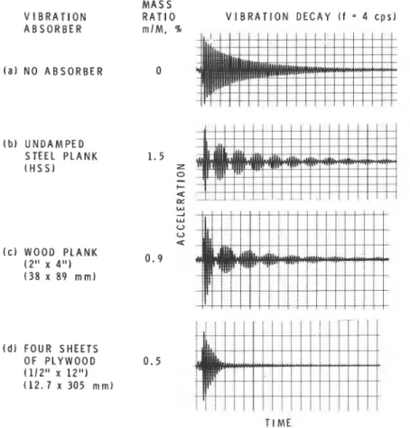
sorbers for controlling wind vibrations in tall buildings. Figure 4 shows results of heel impact tests carried out
CAN. I. CIV. ENG. VOL. 1 1 , 1984 M A S S V I B R A T I O N R A T I O V I B R A T I O N D E C A Y ( f = 4 c p s ) A B S O R B E R m l M . % ( a ) N O A B S O R B E R 0 ( b ) U N D A M P E D STEEL P L A N K ( H S S ) ( c ) W O O D P L A N K ( 2 " x 4 " ) 0 . 9 ( 3 8 x 8 9 m m ) ( d l F O U R S H E E T S O F P L Y W O O D 0 . 5 ( 1 1 2 " x 1 2 " ) ( 1 2 . 7 x 3 0 5 m m l
t ' : I I I I I ! l l I I I I I I l l l I
T I M EFIG. 4. Measurement of natural vibration from heel impact for various vibration absorbers.
on a test floor structure incorporating various vibration are they effective for frequencies below 3 Hz because absorbers at the Division of Building Research, Nation- they cannot control the gradual buildup of vibration due a1 Research Council of Canada (DBRINRCC). They to resonance between footstep frequency (approxi- confirm the principles described above. mately 2 Hz) and natural frequency.
Application of plank vibration absorbers to existing floors
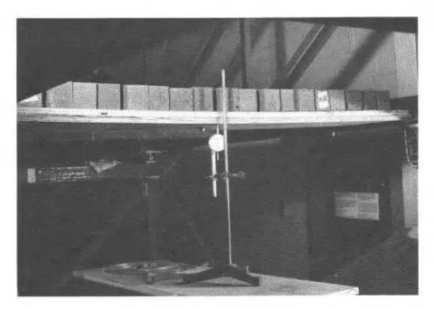
A simple wooden plank or layered system of planks with weights on top can be used as a vibration absorber to improve walking vibration in an existing floor. The planks are supported by the bottom chords of steel joists or by the bottom flanges of steel beams (Fig. 5). Weights (sand bags, concrete blocks, etc.) are added to the planks. A safety device such as a curb or net should be incorporated.
Frequency range
The range of application of vibration absorbers for walking vibration is 3- 12 Hz. For fundamental fre- quencies greater than this, natural vibration from foot- steps is generally not annoying because it decays very rapidly, even for low floor damping. Vibration from static deflection can be a problem, however, but vi- bration absorbers are not effective against this. Neither
Estimation of floor properties
If the troublesome natural frequency (f) of the floor structure is less than 6 Hz, it can be estimated by heel impact on the floor (up on the toes, down on the heels), counting pulsations and using a stop watch. If it is greater, an accelerometer and recording device may be needed.
The mass of the floor (M) per unit span length vi- brating in the troublesome mode can be estimated as follows: for a one-way, steel-joist, concrete deck floor system the effective width is approximately 40 times the thickness of the concrete deck (Canadian Standards Association 1978-see the new edition to appear in 1984); for a girder system, the effective width is deter- mined from the tributary area supported by a girder.
Estimation of absorber weight (mass ratio)
The mass ratio (m/M), and hence the weight of the absorber, is determined according to [2] by the effective
NOTES 115
FIG. 5. Simple plank absorber.
floor damping required to provide satisfactory per- Friction between wood surfaces is too high to achieve formance (m/M = 2to2). Experiments carried out on this, however. Mechanisms to reduce it include placing the DBR/NRCC test floor indicate that the effective polyethylene sheets between planks (Fig. 5) and lo- floor damping required decreases with increase in natu- cating the absorber weight near midspan, where sliding ral frequency. This is due wimarilv to the fact that, for does not occur.
the same damping ratio, vibration ciies out more quickly as the natural frequency increases. An effective damping ratio ranging from 24% in the upper frequency range (8- 12 Hz) to 7% in the lower frequency range (3-5 Hz) generally provides satisfactory performance. This corresponds to a range in mass ratio of f-2%. Knowing the troublesome frequency, one can estimate the approximate mass ratio and hence absorber weight required for satisfactory performance. Such an estimate is needed in designing the planks, as will be described later.
Damping in absorber
The optimum damping ratio of the vibration absorber can be determined by [2] and ranges from 24% for a mass ratio of
4%
to 7% for a mass ratio of 2%. The damping ratio of a wooden plank with a weight on top is about 2%, which is less than optimum. Experiments carried out on the DBR/NRCC test floor indicate that a single wooden plank is often effective when the troublesome frequency is in the upper range, 6- 12 Hz.For troublesome frequencies in the lower range, 3-6 Hz, experiments on the DBRINRCC test floor indicate that more damping is required to eliminate the beating effect shown in Fig. 4c. Friction between planks can be used to increase damping in the absorber (see Fig. 4 d ) , but it must be low enough for sliding to be initiated during noticeable walking vibrations, i.e., where peak accelerations are as low as 1% gravity.
Design of planks
Once the absorber weight has been estimated, the chosen plank stiffness should ensure that the natural frequency of the absorber is approximately equal to the troublesome floor frequency. A useful formula for de- sign is
where S,,,, is the deflection of the absorber due to esti- mated absorber weight. This formula is obtained from the relation between fundamental frequency of a simply supported beam and deflection under its own uniformly distributed weight (Timoshenko et al. 1974). For a single plank the deflection can be determined from the usual beam formula. For a layered friction system, which acts noncompositely during sliding, the load is shared among layers according to relative stiffness. The strength of the planks should be checked under a load of m(g
+
a m ) , where mg is the weight of the absorber and a is the estimated maximum floor acceler- ation. If the acceleration is not known, the load can be approximated by 2mg.Tuning of vibration absorber
The vibration absorber can be coarsely tuned to the troublesome frequency, f , by adding weights until the deflection of the absorber due to its total weight is equal to (17.6/f)' mm. Fine tuning can be carried out by
I t 6 CAN. J. C l V . ENG. VOL. 1 1 , lati4
C Y C L E S
A B S O R B E R M A S S
--
---
. . .
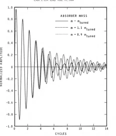
FIG. 6. Effect of inaccurate tuning on natural vibration from footstep.
adjusting weights and checking the absorber frequency in one of two ways. The first is to shake the absorber at a rate corresponding to its natural frequency; if it is properly tuned, resonance vibrations will be observed in the floor structure. The second method is to observe how the absorber responds to a heel impact applied to the floor; if it is in tune, the absorber will vibrate vi- gorously in accordance with the amplification factor
m.
If the troublesome frequency is high, it ispossible that neither method will work very well and an accelerometer with a recording or display device may be required. Figure 6 shows the effect of inaccurate tuning on footstep vibration for the idealized floor sys-
tem of Fig. 1. Evidently a mass within 10% of the
correct one is still quite effective.
Summary
planks are supported by the floor structure and weights are added until the frequency of the plank absorber is equal to the troublesome frequency of the floor struc- ture. If the troublesome frequency is in the upper range, 6- 12 Hz, a simple plank absorber with a mass ratio of
4-;%
can be used. If the troublesome frequency is inthe lower frequency range, 3-6 Hz, a layered plank
system with a mass ratio of
4-
1% can be used. Becausefloors can vibrate with more than one frequency (owing to multiple modes), more than one absorber might be required. Start with one and add others as necessary.
Acknowledgement
This paper is a contribution from the Division of Building Research, National Research Council Canada, and is published with the approval of the Director of the Division.
A simple ~ ~ o d e n plank Or layered system planks CANADIAN STANDARDS ASSOCIATION. 1978. Steel structures
with weights on top can be used as a vibration absorber for buildings--Limit states design, Appendix G , Guide for
LENZEN, K. H. 1966. Vibration of steel joist - concrete slab f frequency of natural vibration
floors. Engineering Journal of the American Institute of g acceleration due to gravity
Steel Construction, 3(3), pp. 133 - 136. m mass of vibration absorber LUm, R. W. 1979. Optimum tuned mass dampers for build-
M
mass of floor structureings. ASCE Journal of the Structural Division, 105(ST12), number of cycles of vibration decay pp. 2766-2772.
TIMOSHENKO, S., YOUNG, D. H., and WEAVER, W. 1974.
ca
damping ratio of absorber 4Vibration problems in engineering, 4th ed., Wiley.
c0
optimum damping ratio of floor structure and ab-sorber, eq. [2]
List of symbols
a acceleration

![[PDF] Cours complet pour débuter facilement avec le langage XSL | Cours informatique](data:image/gif;base64,R0lGODlhAQABAIAAAP///wAAACH5BAEAAAAALAAAAAABAAEAAAICRAEAOw==)