HAL Id: hal-02396194
https://hal.archives-ouvertes.fr/hal-02396194
Submitted on 25 Nov 2020
HAL is a multi-disciplinary open access archive for the deposit and dissemination of sci-entific research documents, whether they are pub-lished or not. The documents may come from teaching and research institutions in France or abroad, or from public or private research centers.
L’archive ouverte pluridisciplinaire HAL, est destinée au dépôt et à la diffusion de documents scientifiques de niveau recherche, publiés ou non, émanant des établissements d’enseignement et de recherche français ou étrangers, des laboratoires publics ou privés.
Modelling Charge Generation and Transport in Low
Density Polyethylene Irradiated by an Electron-Beam
M.E. Banda, Virginie Griseri, G. Teyssedre, Séverine Le Roy
To cite this version:
M.E. Banda, Virginie Griseri, G. Teyssedre, Séverine Le Roy. Modelling Charge Generation and Transport in Low Density Polyethylene Irradiated by an Electron-Beam. 2018 IEEE 2nd International Conference on Dielectrics (ICD), Jul 2018, Budapest, Hungary. �10.1109/ICD.2018.8514663�. �hal-02396194�
Modelling Charge Generation and Transport in Low
Density Polyethylene Irradiated by an Electron-Beam
M.E. Banda, V. Griseri, G. Teyssedre and S. Le Roy* LAPLACE, CNRS and University of Toulouse, France Abstract—One way to bypass charge generation due to
injection in an insulator sandwiched between parallel electrodes and submitted to an applied voltage is to implant charges in the material with the help of an electron beam. The electrons position and quantity is theoretically known as long as the beam energy and beam current are known. Low density polyethylene (LDPE) has been characterized with in-situ space charge measurements by pulsed electroacoustic method during irradiation, and with ex-situ measurements while a DC voltage is applied. A fluid charge transport model has been developed using a commercial software, to reproduce the space charge behaviour during and after irradiation. Simulated results during irradiation are first compared to in-situ space charge measurements, in order to validate the model parameters related to e-beam irradiation. Simulations are then performed on post-irradiated samples, polarized under different electric fields. Space charge measurements and current measurements are available for comparison. Simulated results are in relatively good agreement with experimental ones as long as the model parameters are adapted to irradiated low density polyethylene, compared to a best set of parameters adapted uniquely for non-irradiated polyethylene.
Keywords—LDPE, charge generation and transport, fluid model, electron-beam irradiation, ageing.
I. INTRODUCTION
Applying a DC voltage on an insulator sandwiched between parallel electrodes is a common way to investigate space charge generation and transport in such materials. The physical processes occurring at the interface remain however complex to understand, as charge injection is not only dependent upon the insulating material, but also upon the contact type, its roughness, the chemicals at the surface and the way the interface has been processed, etc [1]. One way to bypass injection processes is to use an electron beam, where the quantity and position of charges are normally known given the electron beam energy, its flux density and the properties of material under study. However, other processes, linked to charge generation due to the beam, are also not trivial to understand. Low density polyethylene (LDPE) has been used to characterize the behaviour of space charge during irradiation and irradiation. In the particular case of post-irradiated samples where a voltage is applied, a peculiar behaviour, with strong charge build-up, has been observed [2].
In this contribution, a bipolar charge transport model has been used to predict the space charge behaviour in non-irradiated LDPE as a reference, and in electron beam
irradiated LDPE, for most of the available experiments under irradiation and post-irradiation. A comparison of the results obtained between experiments and simulations under irradiation and post-irradiation is proposed. The model is globally able to predict the experimental behaviour, provided changes in the material parameters are achieved. These changes traduce the modifications in the chemical structure of the material under irradiation.
II. MATERIAL, MEASUREMENTS PROCEDURE AND MODEL
A. Material and experimental procedure
LDPE samples of thickness 300 µm were prepared from pellets using a hydraulic press in our laboratory, to ensure sample reproducibility. LDPE samples are then inserted in an irradiation chamber, under a vacuum of ~10-7 mbar, and submitted to a 80 keV electron-beam for 8 minutes with a current flux of 1 nA/cm2. Charge density profile distributions could be determined in situ, i.e. under vacuum conditions, using the in-situ Pulsed Electro-Acoustic (PEA) space charge set-up under open circuit conditions [3]. Samples could also be removed from the irradiation chamber, i.e. they return to atmospheric pressure, and characterized outside the chamber, using different set-ups (space charge measurements, current measurements, luminescence techniques, and physico-chemical characterizations, such as FTIR or DSC). Space charge measurements will be presented under vacuum conditions, and post-irradiation current measurements will also be presented and compared to simulation results.
B. Model description
A numerical model, based on the one proposed earlier [4], has been developed using a commercial software to reproduce the space charge behavior in an electron-beam irradiated LDPE, for configurations encountered in the experiments, i.e. under vacuum conditions during irradiation, and at atmospheric pressure after electron beam irradiation, under applied voltage. The resolution of the model using COMSOL Multiphysics® is performed with the help of the mathematical module, for each equation. The model features bipolar injection of carriers at the electrodes, conduction using an electric field and temperature dependent mobility (i.e. of the hopping type), for each kind of carriers. Charge of each polarity can be trapped into a single level of deep trap, from which they can escape, via a thermally activated process. Langevin recombination is also taken into account [4]. The physical hypotheses linked to the electron beam irradiation have been adapted from Sessler et al [5], and
are linked to electron deposition, and electron/hole pair generation. The equations to solve are:
- The Poisson equation:
∂E(x,t) ∂x = ρ
(x, t) ε0εr
(1) where E(x,t) is the electric field, x is the direction perpendicular to the electrodes, ε0 is the vacuum permittivity,
εr is the dielectric permittivity (2.3. in the case of LDPE), and
ρ is the net charge density, which can be written as:
ρ(x,t) = e −n
(
eµ(x, t)− net(x, t)+ nhµ(x, t)+ nht(x, t))
(2)where n is the particles density (m-3), e is the elementary charge, the indexes e and h refer to the type of charge, i.e. electron or hole, and µ and t refer to mobile or trapped charges respectively.
- The continuity equation: ∂ne,h(x, t) ∂t + 1 e ∂je,h(x, t) ∂x = si(x, t) (3)
where t is the time, and si(x,t) are the source terms, which encompass the changes in local density not linked to transport. - The transport equation, where je,h is the conduction current density for each kind of carrier, neglecting diffusion:
je,h(x,t) = ±eneµ,hµ(x,t)µe,h(x,t)E(x,t) (4) where µe,h refers to the mobility, which is of the hopping type:
µe,h(x, t)= 2νd E(x, t)exp − ewhop(e,h) kBT sinh eE(x, t)d2k BT (5) where ν is the attempt to escape frequency, d the distance between traps, whop(e,h) is the hopping barrier height for electrons and holes, kB the Boltzmann constant, and T the temperature.
An example of source term for mobile electrons is given here:
(6)
where S0 to S3 refer to the recombination coefficients, Be,h, are the trapping coefficients, and De,h are the detrapping coefficients. G(x) is the electron/hole pair generation, and is of the form [5]:
G(x)= G0.D(x) (7)
where G0 is the electron/hole pair generation coefficient and D(x) the normalized dose rate deposited by the electron beam. G(x) is void in the non irradiated region (NIR). J0(x) in (6) refers to the beam current density in the dielectric. Note here that once thermalized, primary electrons are considered as a source term for mobile electrons in the model. Also, carriers issued from pair generation are initially mobile.
Generation of positive or negative charges is possible through a modified Schottky law [6], the nature of injected carriers being function of the polarity of the electrode:
jinj(x, t)= AT2exp −e.winj kBT exp ke BT e.E(x, t) 4.π.ε0.εr −1 (8) where A is the Richardson constant, and winj the injection barrier height. In the case of vacuum conditions, i.e. under irradiation, there is no possible injection at the irradiated face, and only charge injection is effective at the ground electrode. In the case of post-irradiation conditions, where the LDPE samples are sandwiched between two electrodes, injection of positive/negative charges is possible at each electrode, depending on the sign of the electric field.
Simulations have been performed, using an open access code called PENELOPE [7] to calculate the electron path length distribution as well as the dose rate deposited inside LDPEfor an electron beam of energy 80 keV and a flux of 1 nA/cm2. This code allows simulating the trajectory of a large number of particles over a wide energy range, accounting for the matter-radiation interactions. Profiles of the normalized beam current density and the normalized dose are given in Fig.1 as a function of the sample thickness. The irradiated region extends over 125 µm from the irradiated face.
III. SIMULATION RESULTS
A. In-Situ conditions
Space charge measurements have been performed using the in-situ PEA set-up, on a 300 µm thick LDPE submitted to the irradiation conditions previously described for 8 min.
Fig. 1. Normalized electron density and normalized dose as a function of the position in the sample calculated by PENELOPE for a 300 µm thick LDPE
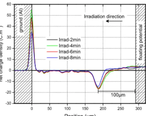
Fig. 2. Experimental space charge profiles measured on a 300 µm LDPE with the 'in situ' PEA under vacuum conditions for 10 min of irradiation with a 80
keV electron beam.
Fig. 2 presents the space charge profiles function of the position in the sample for different irradiation times. It is to note that irradiation comes from the right side. A negative peak is observed with a peak maximum located at around 100 µm from the irradiated face. A positive peak, located at the ground electrode, shows the positive image charge due to the negative charge inside the bulk. Note that as PEA measurements are carried out in open circuit conditions, there are no image charges on the right side of the sample. The maximal value of the negative peak inside the bulk seems to be reached after around 4 min of irradiation. After this time, the peak amplitude seems to stabilize or even to decrease. This is certainly due to the fact that the electron beam does not irradiate the entire sample thickness, so charges accumulate, and enhance the surface potential at the irradiated face. Surface flashovers may have happened during the irradiation time, thus also discharging the sample in the bulk.
Most of the parameters for the simulations can be found in the literature, or have already been adapted for this model for non-irradiated LDPE [8]. However, the coefficient related to generation of electron/hole pair due to the dose, G0, remains difficult to evaluate [4]. A sensitivity analysis has been performed on this parameter, letting the other parameters as in Table 1, to be as close as possible to the experimental results (Fig. 2).
Fig. 3. Simulated net charge density function of the position, for different values of the electron/hole pair coefficient G0, for 10 min of irradiation.
TABLE I. OPTIMIZED PARAMETERS USED FOR ALL THE SIMULATIONS
Fig. 3 shows the simulated space charge distribution after 10 min of irradiation for different values of G0. In this figure, no image charge has been added to the simulated profiles. When G0 increases, i.e. when the generation of positive/negative charges increases inside the bulk, the net charge density remains negative but the peak position shifts towards the ground electrode and its magnitude increases, with a decrease of the spread of charges. A parameter G0 of 8 C.m-3.s-1 seems the best to fit the experimental data.
Simulations have then been performed with the parameters of Table 1 and for the same conditions as for Fig. 2. The top PEA electrode is supposed to be at 1 mm from the surface. The simulated space charge profiles are presented in Fig. 4 for different irradiation times. Image charges are added to the simulated results, allowing a better comparison with the experimental profiles. As in the experiment, the net charge density remains negative during irradiation, even if positive charges are generated by the electron beam and injected at the ground electrode, due to a favorable electric field. The peak maximum is located at 90 µm from the irradiated face, which is consistent compared to the experimental results. The value of the peak maximum is of the order of 40 C.m-3, which is twice the one observed experimentally after 8 min of irradiation. However, the model does not take into account the possible discharges that occur during irradiation due to a too high floating potential. Globally, the simulated net charge density profiles are comparable to the experimental ones.
B. Atmospheric (ex-situ) conditions
Conduction current measurements and related simulations were then performed on non-irradiated and post-irradiated LDPE samples at atmospheric pressure (Fig. 5). The protocol of application of the voltage consists in increasing the applied electric field by steps of 5 kV/mm with a resting time of 10 min at each step, up to 100 kV/mm.
Symbol Value Units
Trapping coefficient Be electrons Bh holes 1.10-2 2.10-2 s -1 s-1
Hopping barrier for mobility Electrons holes 0.713 0.636 eV eV
Deep trap density
Noet for electrons
Noht for holes
100
100 C m
-3
C m-3
Schottky injection barrier (irradiation conditions)
wei for electrons
Whi for holes (Al)
∞ (no injection)
1.22 eV eV
Schottky injection barrier (MIM conditions)
wei for electrons (Au)
Whi for holes (Au)
1.3
1.13 eV eV
Detrapping barrier height
wtre for electrons
Wtrh for holes
0.99
1.02 eV eV
Electron / hole pair generation coefficient
Fig. 4. Simulated space charge profiles measured on a 300 µm LDPE with the 'in situ' PEA under vacuum conditions for 10 min of irradiation with a 80 keV
electron beam.
The set of parameters used for the simulations are given in Table I, using the Schottky injection barriers referring to 'MIM' conditions. Each point of the experiment/simulation is an average of current over the last minute in each field step. The shape of the current-field characteristic is of SCLC - space charge limited current- type, for a non-irradiated and an irradiated sample. At low fields, there is more than one decade difference in current between the irradiated and the non-irradiated sample. For electric fields above 40 kV/mm, this difference decreases and it seems that the shape of the characteristic for the irradiated sample draws closer to the one of the non-irradiated one. This behavior seems consistent with space charge measurements performed on post-irradiated samples, where more charges are measured compared to non-irradiated samples [2]. At higher electric fields, the charge injection becomes dominant compared to the charge generated by the electron beam, and the sample behavior comes back to a non-irradiated behavior.
Simulated currents for non-irradiated and irradiated samples are in good agreement with the experiment for fields below 70 kV/mm. The difference in current density between the irradiated and the non-irradiated sample could be reproduced. The simulated results also reproduce the SCLC shape, even if the model is not based on this hypothesis, with a first slope of 1 for fields below 10 kV/mm, and a slope of 2 for fields between 10 and 60 kV/mm. Above this field, the model predicts a large increase of the slope in current density, which is not observed experimentally. However, the model also predicts a current density for the irradiated sample that comes closer to the non-irradiated behavior, as the difference is less than a decade for an electric field of 100 kV/mm. These simulated results have been obtained with the optimized set of parameters of Table I, which are not the same as the one optimized for a non irradiated LDPE based on space charge and current data for MIM structures [8]. Irradiating the LDPE sample, even for a so short time, can change its chemical structure irreversibly. On the basis of physico-chemical measurements (FTIR, RMN and DSC), this is what has been concluded, even if the changes are in a small range. Changes in the physico-chemical structure imply also changes in the trapping, and detrapping behavior, and hence in the parameters linked to these processes.
Fig. 5. Experimental and simulated conduction current density as a function of the applied electric field. Step-wise increase protocol. Optimized parameters
of Table I.
The main changes in the parameters of the model are the decrease of the trapping coefficients, by one decade, and the value of the detrapping barrier, for holes mainly.
IV. CONCLUSIONS
Various experiments have been performed on electron-beam irradiated LDPE samples, in situ and in post-irradiation, in order to comprehend the specific behavior of charge generation and transport within the material. A bipolar fluid charge transport model has then been used to predict the space charge behavior in the same experimental conditions, for most of the in-situ and post-irradiation experiments. This model is globally able to reproduce the experimental data, i.e. the hypotheses of the model seem enough to describe the space charge behavior. However, this goal has been reached by changing some of the optimized parameters of the model, mainly the trapping and detrapping parameters. These parameters being linked to the chemical structure of the sample, one could think that the experimental protocol used to characterize the LDPE samples is enough to age the material, and that the changes in the simulation parameters is a consequence of these chemical changes. However, more work needs to be done, mainly on the time of irradiation, in order to validate these conclusions.
REFERENCES
[1] M. Taleb, G. Teyssedre and S. Le Roy, IEEE Int. Conf. on Electrical
Insulation and Dielectric Phenomena, Virginia Beach (Virginia, USA), 18-21 Octobre 2009, Proc. CEIDP 2009, pp 112-115, 2009.
[2] M.E. Banda, V. Griseri, G. Teyssedre and S. Le Roy, J. Phys. D: Appl.
Phys. 4, 085304-1/8, 2018.
[3] C. Perrin, V. Griseri and C. Laurent, IEEE Trans. Dielectr. Electr. Insul.
15, pp. 958–64, 2008.
[4] S. Le Roy, F. Baudoin, V. Griseri, C. Laurent, and G. Teyssedre, J.
Appl. Phys. 112, 023704/8, 2012.
[5] Sessler G M, Figueiredo M T and Ferreira G L IEEE Trans. Dielectr.
Electr. Insul. 11, pp. 192-202, 1995.
[6] F. Boufayed, G. Teyssèdre, C. Laurent, S. Le Roy, L.A. Dissado, P. Ségur and G.C. Montanari, J. Appl. Phys. 100, 104105, 2006.
[7] J. Baro, J. Sempau, J.M. Fernández-Varea and F. Salvat Nucl. Instr.
Meth. Phys. Res. B 100, pp. 31-46, 1995.
[8] S. Le Roy, G. Teyssedre, C. Laurent, G.C. Montanari, F. Palmieri,