HAL Id: inria-00636143
https://hal.inria.fr/inria-00636143
Submitted on 6 Apr 2014
HAL is a multi-disciplinary open access
archive for the deposit and dissemination of
sci-entific research documents, whether they are
pub-lished or not. The documents may come from
teaching and research institutions in France or
abroad, or from public or private research centers.
L’archive ouverte pluridisciplinaire HAL, est
destinée au dépôt et à la diffusion de documents
scientifiques de niveau recherche, publiés ou non,
émanant des établissements d’enseignement et de
recherche français ou étrangers, des laboratoires
publics ou privés.
PAC-C3D: A New Software Architectural Model for
Designing 3D Collaborative Virtual Environments
Thierry Duval, Cédric Fleury
To cite this version:
Thierry Duval, Cédric Fleury. PAC-C3D: A New Software Architectural Model for Designing 3D
Collaborative Virtual Environments. ICAT 2011, VRSJ, Nov 2011, Osaka, Japan. pp.53-60.
�inria-00636143�
PAC-C3D: A New Software Architectural Model for Designing 3D
Collaborative Virtual Environments
Thierry Duval∗
Universit ´e de Rennes 1, IRISA UMR CNRS 6074, Rennes, France
C ´edric Fleury†
INSA de Rennes, IRISA UMR CNRS 6074, Rennes, France
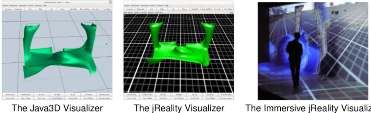
The Java3D Visualizer The jReality Visualizer The Immersive jReality Visualizer
Figure 1: Three different visualizers sharing the same virtual environment
ABSTRACT
We propose PAC-C3D as a new software model for 3D Collabo-rative Virtual Environments (CVE). This model merges the results from two research fields: distribution models for CVE and HCI de-sign for computer-supported cooperative work. PAC-C3D proposes to describe each part of a shared virtual object through explicit in-terfaces to ensure a strong separation between the core functions of a virtual environment, its (visual) representations, and its collab-orative features such as synchronization and consistency mainte-nance between remote users. PAC-C3D makes it possible to design a CVE with low dependency between the core functions, the distri-bution mode and the 3D graphics API used. It explicitly deals with the main distribution modes encountered in CVE. It makes it easy to use different 3D graphics API for different nodes involved in the same collaborative session, providing interoperability between these 3D graphics API. It also makes it possible to integrate other kinds of 3D representations such as physics engines into the CVE. Index Terms: H.5.2 [Information Interfaces and Presentation (e.g., HCI)]: User Interfaces—Theory and methods; H.5.3 [In-formation Interfaces and Presentation (e.g., HCI)]: Group and Organization Interfaces—Computer-supported cooperative work (CSCW); I.3.7 [Computer Graphics]: 3-Dimensional Graphics and Realism—Virtual reality; D.2.11 [Software Engineering]: Software Architectures—Patterns I.3.6 [Computer Graphics]: Methodology and Techniques—Interaction techniques, Device independence
1 INTRODUCTION
The design of 3D Collaborative Virtual Environments (CVE) merges the design of interactive 3D applications and the design of distributed collaborative applications. This task is complex be-cause it must address 3D interaction and immersion issues as well
∗e-mail: [email protected] †e-mail: [email protected]
as collaborative issues dealing with distribution, synchronization, and consistency maintenance of the shared virtual environment.
The configuration (adaptation to the hardware deployment sys-tems) of CVE is complex because it must address various network characteristics (from high bandwidth on professional or experimen-tal networks to low bandwidth on personal networks) as well as var-ious displays and 3D interaction devices (from 6-face Caves [8] to simple workstations or even to simple interactive tablets). All these configurations can even be used at the same time in a single deploy-ment in order to make asymmetric collaboration possible between remote users using different input and output devices.
To meet all these requirements, these CVE must be designed ac-cording to a software architectural model that makes it possible to adapt the distribution mode of a CVE to solve the network interop-erability issues. Such a model should also make it possible to de-sign software components that encapsulate the hardware 3D graph-ics requirements, in order to be able to choose at run-time the best components for each hardware configuration. Existing solutions focus either on how to manage distribution and consistency main-tenance for 3D CVE, or on how to manage independence between core functions and graphics API for 2D CSCW. For now, design models for CVE deal neither with independence to 3D graphics API nor with efficient management of distribution modes.
So we propose to merge these two main research fields in or-der to provide a new solution, the PAC-C3D model, which offers a better way to design and implement CVE. PAC-C3D meets two re-quirements: ensure synchronization and consistency maintenance of CVE, and ensure independence of CVE from 3D graphics en-gines to make interoperability possible between such 3D enen-gines.
In this paper, section 2 presents the context of our work: the need to design CVE with various distribution models. Section 3 presents the software architectural models used in the field of HCI and CSCW. Section 4 presents our new software architectural model and how its instances communicate together. Consistency maintenance is explained in section 5 for each of the main distribu-tion modes. Then secdistribu-tion 6 describes how this model can be used to address the problem of interoperability between 3D API, for 3D graphics or physics engines. Finally, section 7 gives some imple-mentation examples illustrating how our model faces adaptation to different distribution situations and to different 3D engines.
2 THECONTEXT:DISTRIBUTED ARCHITECTURES FORCVE
The location of the virtual environment data (i.e. geometric data, textures, etc.) is a critical decision when designing a CVE sys-tem [23]. It determines which nodes (usually the users’ computers) store this data, which nodes execute the processing related to each virtual object, and how the synchronization of the distributed ob-jects is achieved. We distinguish three data distribution modes: ho-mogeneously replicated, centralized, and partially replicated [19], which is similar to the approaches presented in [12]. A more com-plete overview of synchronization and data distribution within CVE can be found in [10, 11, 20].
2.1 Duplication: homogeneous replicated world
In replicated CVE systems all nodes are initialized with the same database that contains all the informations about the virtual environ-ment (geometric models, textures, object behaviors, etc.). During a session, the database evolves independently on each node and all object behaviors are executed locally. Object modifications are per-formed locally before being sent to the other nodes by using update messages.
So latency is very low during user interactions. However, in-consistencies between users’ states of the virtual environment can appear because of delays or losses during messages transmissions. Additional mechanisms must also be used to manage concurrent access to the objects to avoid conflicts.
2.2 Centralization: shared centralized world
In centralized systems all the CVE data is stored on a central server (client/server network architecture). Similarly, virtual object be-haviors are executed on this server. When a user wants to modify an object, he sends a request to the server. The server processes the modification request, then transmits the up-to-date state of the object to all the nodes, including the one that has asked for modifi-cation.
This method implicitly ensures consistency between all the nodes and avoids data replication. However, this architecture can introduce latency during user interactions because each modifica-tion request has to pass through the server, and a performance “bot-tleneck” can appear on the server when there are many users.
2.3 Hybrid solution: partially replicated world
Many CVE systems choose hybrid solutions between totally cen-tralized and totally replicated data distributions, mixing features to meet particular requirements of consistency and responsiveness. These solutions distribute the data and their processing among the nodes. Most of the time, a referent/proxy paradigm is used for each object. Proxies maintain a local copy of the virtual environment, only receiving update messages from the referent.
This distribution mode makes a trade-off between the advantages and drawbacks of the two other data distributions.
2.4 Dynamic solution: mixing all the modes
Some distribution mechanisms, such as the distribution model of the Collaviz system [19] even propose a mix of these three distribu-tion modes, allowing each object to change dynamically at run-time its own distribution mode.
2.5 Synthesis about distribution modes
As each distribution mode has its own advantages and drawbacks, a good software architectural model for CVE should be able to manage these three main distribution modes and should be flexible enough to provide solutions for evolution toward new distribution or synchronization modes.
3 RELATEDWORK: MODELS FORHCIANDCSCW
A lot of research work about architectural models for human-computer interaction (HCI) deals with separating clearly the graph-ics part of interactive software from its core part. Some of these models have been adapted to the context of computer-supported collaborative work.
3.1 Software architectural models for HCI
The most commonly used software architectural models for HCI are based either on the Model-View-Controller (MVC) model [26, 21] or on the Presentation-Abstraction-Control (PAC) model [7]. Both of them have inspired many models dedicated to particular situa-tions: for example for Struts web-based applications (MVC-2 [9]), for C++ or Java applications (Model-View-Presenter (MVP) [25]) or for multi-modal applications (PAC-Amodeus [24]).
MVC divides interactive components into three parts: the Model, the View and the Controller (see figure 2(a)).
Figure 2: (a) The MVC model — (b) The PAC model
“The Model represents data and the rules that govern access to and updates of this data. . . . The View renders the contents of a
Model. It specifies exactly how the Model data should be presented. If the Model data changes, the View must update its presentation as needed. This can be achieved by using a push model, in which the
Viewregisters itself with the Model for change notifications, or a pull model, in which the View is responsible for calling the Model. . . . The Controller translates the user’s interactions with the View into actions that the Model will perform. . . . ” [16]
So the Model and the View of MVC can be closely coupled, con-trary to the formal separation achieved by PAC between these two kinds of components.
PAC divides interactive components into three parts: the
Pre-sentation, the Abstraction and the Control (see figure 2(b)). At first look, one could consider that PAC is just another name for MVC where Presentation could stand for View, Abstraction could stand for Model and Control could stand for Controller. In practice, the PAC components have a quite different behavior than the MVC components.
“The Presentation defines the concrete syntax of the application, i.e. the input and output behavior of the application as perceived by the user. The Abstraction corresponds to the semantics of the application, it implements the functions that the application is able to perform. . . . The Control maintains the mapping and the consis-tency between the abstract entities involved in the interaction and implemented in the Abstraction, and their Presentation to the user. It embodies the boundary between semantics and syntax. It is in-tended to hold the context of the overall interaction between the user and the application.” [7]
So the Abstraction and the Presentation are not allowed to com-municate directly: the Control acts as a mediator and filters all the communications between its Abstraction and Presentation, and with the other Controls.
In fact, most of the MVC-like models propose also this separa-tion between the Model and the View, as detailed in the Oracle/Sun interpretation of MVC [16], which is very similar to the PAC model. To ensure a better independence between these three kinds of components, the Arch model [27] proposes to add adaptor compo-nents between them (see figure 3). This model is also considered as a meta-model for other software models, which should follow this generic separation between facets of interactive components.
Figure 3: The Arch model
These models must now be extended to manage the collaborative aspects of CVE.
3.2 Models for collaborative HCI
Several adaptations of the PAC and Arch models have been pro-posed to cope with these collaborative features. These approaches rely on Ellis’s conceptual model of groupware [17] or on the clover conceptual model [22]. Ellis’s model proposes three complemen-tary components or models: the ontological model, the coordina-tion model, and the user-interface model. The clover conceptual model proposes to divide the services of collaborative software into three main parts: production, communication and coordination (see figure 4(a)). The ontological model and the production space re-fer to the shared virtual objects of a CVE. The coordination model and the coordination space cover the consistency maintenance in the CVE. The user-interface model refers to the representation of human-computer interaction while the communication space refers only to the communication between the users of a CVE.
PAC∗[6] (see figure 4(b)) dispatches these three kinds of
func-tions across the three PAC facets. To our opinion, this is a problem for designing Abstractions independently from the collaborative as-pects.
Figure 4: (a) The clover concepts — (b) The PAC∗model
Clover [22] (see figure 5(b)) is an extension of PAC∗that relies
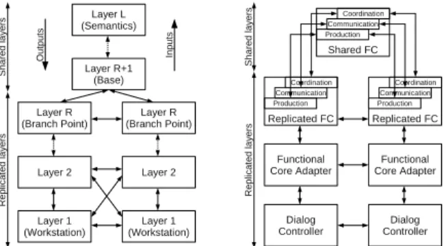
on Dewan’s “generic multi-user architecture”[12] (see figure 5(a)), which is a collaborative extension of the Arch model. Here again, each unit of the model can contain three sub-components about pro-duction, communication and coordination, especially the higher-level units that correspond to the core of the CVE.
Figure 5: (a) Dewan’s model — (b) The Clover model
3.3 Synthesis about HCI models and collaboration
Software architectural models for HCI propose to divide interactive components in three kinds of components that should be as inde-pendent as possible from each other. Some of these models have been extended to address the design of CVE, according to the clover conceptual model, but they do not address how to cover the three main distribution modes of the CVE. Furthermore, they spread the collaborative aspects over all the components of the models, which is a problem for designing Abstractions that should not be aware of the collaborative aspects.
This is why we need a new model for designing 3D CVE, which would ensure the best possible separation between core functions, visualization (3D graphics API and libraries) and collaboration as-pects, and which would provide explicit solutions to achieve these different synchronization modes.
4 PACFOR COLLABORATIVE3DAPPLICATIONS
4.1 Interfaces for independence between components
In order to make the PAC facets independent from each other, we choose a special interpretation of the PAC model that pro-poses interfaces to specify the features of each facet of the model. An important feature of this model is that the Control is a Proxy (GoF207)[15] of its associated Abstraction.
We present figure 6 a new interpretation of this model in order to allow the presence of several Presentations associated to the same
Control. Each virtual shared object will be described through 3 interfaces:
• Interface for the Abstraction (IA): it declares the methods in charge of the object behavior and the methods allowing to set and get its attributes.
• Interface for the Presentation (IP): it declares the methods allowing to set and get the attributes of the representation of the object (for example the position of its 3D visualization). • Interface for the Control (IC): it declares all the methods of
the Interface for the Abstraction, as the Control will be used to manage the access to the Abstraction (the Control will be the proxy of the Abstraction) to maintain consistency between the Abstraction and all the Presentations, and some methods dedicated to the communication with its Presentations and the other Controls.
Figure 6: The PAC model with interfaces between facets
As these interfaces will be implemented by the real facets of the PAC components, at run time these facets will be instances of:
• Abstraction (A): it implements the object model and behavior, and the setters and getters.
• Presentation (P): it implements the object representation: for example it can use a 3D graphic API to visualize the object and its properties.
• Control (C): it implements the consistency maintenance be-tween the Abstraction and the Presentations, and it regulates the access to the Abstraction.
Very often, a Presentation is closely coupled to a 3D graphics API, but thanks to the Interface for the Presentation, the Control will be totally independent of this 3D API.
In the same way, thanks to the Interface for the Control, the
Pre-sentationsand Abstraction will be totally independent from the im-plementation of the Control.
4.2 Adapting PAC to collaboration
As for the PAC∗model [6] and the Clover model [22], here again
the PAC model will be the basis of our proposition, but unlike these two models, the collaborative parts will not be spread out into all the components of the model, but only into the Control of the PAC components.
Indeed, we consider that the objects of the production space should remain in the core parts of a 3D CVE, and that their coordi-nation should be achieved by the Control of the PAC components. Last, we consider that communications between users should be either totally integrated within a 3D CVE through shared virtual objects, or totally independent of the 3D CVE, so these communi-cation aspects are not central to a model dedicated to the design of 3D CVE. In our opinion, the distributed aspects should not impact the Presentations and Abstraction of a PAC component, in the same way that the 3D graphics details should be limited inside the
Pre-sentationsand that the core concepts should remain in the
Abstrac-tion. This independence is possible thanks to the three interfaces of our model.
Figure 7: Adaptation of the PAC model for 3D CVE
The Control is associated to one distribution policy, dedicated to synchronization and consistency maintenance. There are three distribution policies:
• Referent distribution policy (RDP): implementation of what is needed to manage the set messages and to distribute updates to other Controls: each time the value of a parameter of the object is set, this policy makes the referent Control send (for example using multicast) an update message to the distributed proxy Controls so that they can also update their
Presenta-tions.
• Proxy distribution policy (PDP): implementation of what is needed to transmit the set messages toward the referent
Con-trol, and to manage the update messages returned by the ref-erent Control: each time the value of a parameter of the object is set, this policy makes the proxy Control send a set message to its referent Control, and this value will be effectively set only when the proxy Control will receive an update message from its referent Control.
• Duplicated distribution policy (DDP): same management of the set messages as the RDP, and same management of the update messages as the PDP.
These components will be distributed across the network accord-ing to the number of nodes in a collaborative session and to the architecture chosen for the distribution.
5 DEALING WITH DISTRIBUTION MODES
In this section we will detail the behavior of PAC-C3D Controls according to their associated distribution policy, in order to show that this behavior is able to deal with the three main distribution modes for CVE.
We will consider a modification of the value of a parameter of a virtual object occurring from a presentation component where a user will have made an action upon a shared virtual object, and we will trace the subsequent communications between the PAC-C3D components and facets.
5.1 PAC-C3D and duplicated architecture
In a CVE with a typical duplicated architecture, for each shared virtual object there will be as many instances of Abstractions,
Pre-sentationsand Controls with a duplicated distribution policy (DDP) as there are visualization nodes embedding one or several represen-tations of the shared virtual universe.
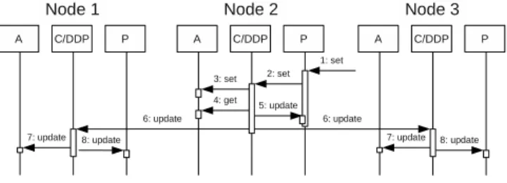
Figure 8: PAC-C3D and duplicated architecture
Figure 8 presents a typical duplicated architecture with three nodes. The exchanges between the facets of the PAC-C3D com-ponents will be as follow:
1 An action occurs upon the Presentation of a virtual object, on one node, to set the value of one attribute of this virtual object. This Presentation does not set the attribute, but instead asks its Control for a modification.
2-5 This Control receives the set request and transmits it to its
Ab-straction. This Abstraction processes the set requests in its own way: the final value of the attribute of the Abstraction can be different from the value proposed by the Control, for example because a proposed value could put the Abstraction into an incorrect status. This is why the Control then asks its
Abstractionfor the effective value of the attribute and updates its Presentation with this new value. Then the Control trans-mits this value to the other duplicated Controls by sending them an update message (this sending can be synchronous but it is more efficient to make it asynchronous to allow all the duplicated Controls to process the update at the same time). 6-8 Finally on each other node a duplicated Control receives the
update message and asks its Abstraction and then its
Presen-tationfor an update.
As we have seen in section 2.1, the main advantage of this ar-chitecture is that when a user interacts with an object, he obtains an immediate feedback. Then all the other users may perceive the re-sult of the interaction at the same time, with a delay corresponding to the network latency. The main drawback of this architecture is that it must ensure a strong synchronization between the nodes be-cause of the potential autonomous behavior of some shared virtual objects. It is also quite impossible to allow several users to interact directly at the same time on a same shared virtual object.
5.2 PAC-C3D and centralized architecture
In a CVE with a typical centralized architecture, for each shared virtual object:
• there is only one instance of Abstraction, on the server, • there are as many instances of Presentations as there are
visu-alization nodes embedding one or several representations of the shared virtual universe,
• there is only one instance of Control with a referent distribu-tion policy (RDP), without Presentadistribu-tion,
• there are as many instances of Control with a proxy distribu-tion policy (PDP) as there are Presentadistribu-tion instances.
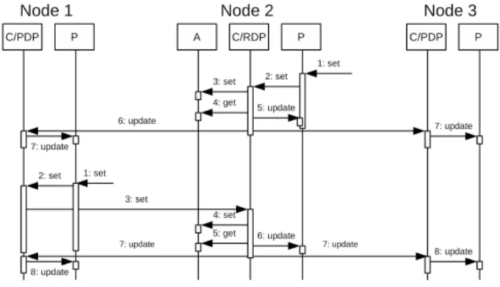
Figure 9: PAC-C3D and centralized architecture
Figure 9 presents a typical centralized architecture with one server and two clients. The exchanges between the facets of the PAC-C3D components will be as follow:
1-2 On one client an action occurs upon the Presentation of a vir-tual object, and this Presentation asks its proxy Control for a modification. This proxy Control transmits the set request to its referent Control (this transmission can be synchronous or asynchronous).
3-5 The referent Control transmits the value to its Abstraction. Here again this Abstraction processes the set requests in its own way and then the Control asks its Abstraction for the ef-fective value of the attribute. Then it transmits to its proxy
Controlby sending them an update message (here again this sending should be asynchronous).
6-7 Finally on each client a proxy Control receives the update mes-sage and asks its Presentation for an update.
As we have seen in section 2.2, the main advantage of this archi-tecture is that all the users may perceive the result of the interaction at the same time, but the drawback is that the delay for the semantic feedback is about twice the network latency. Another interesting property of this distribution policy is that it is not absolutely nec-essary to have a strong synchronization between all the nodes as all the behaviors are executed on the server node. Last, it is easy to allow several users to interact at the same time with the same object as the referent Control will be in charge of centralizing all the interactions coming from all the nodes: it can integrate all the concurrent propositions to compute a single result.
5.3 PAC-C3D and hybrid architecture
In order to answer more quickly to a user’s interaction with a virtual object, it can be interesting to locate the Abstraction of this object on this user’s node, which means to allow the referent to be on a client node rather than to stay on a centralized server. So we can consider that the hybrid architecture is a simple evolution of the centralized architecture where all the referents are not necessarily on the same node and where a centralized server is not absolutely necessary any longer.
In such a case, there will be two different situations while in-teracting with a virtual object, as described figure 10: either the
Abstractionof the object is on the same node than the user, either it is on another node.
Figure 10: PAC-C3D and hybrid architecture
If the Abstraction of the object is on the node of the interacting user, this user will obtain an immediate interaction feedback, while the other users will perceive the interaction with a small lag mainly due to the network latency. This is very similar to the behavior of the duplicated architecture.
If the Abstraction of the object is not on the node of the interact-ing user, the user on the node of the Abstraction will be the first to perceive the result of the interaction, and all the other users (even the one who is interacting) will see the result of the interaction at the same time, with a delayed feedback about twice the network latency. This is quite similar to the behavior of the centralized ar-chitecture.
In both cases this hybrid solution offers the same possibility as the centralized architecture to enable several users to interact at the same time with a same object. And as we have seen in section 2.3, it also has the same main drawback as the duplicated architecture about the necessity to synchronize all the nodes because each node can be in charge of the behavior of some virtual objects.
5.4 Adapting distribution policies
To change the distribution mode of a system designed according to our model, for example to transform a centralized architecture to a hybrid architecture or to a duplicated architecture, we only have to change the distribution policy of the Controls: it impacts neither the Abstractions nor the Presentations. It is even possible to change dynamically the distribution policy of a Control, by replacing its current distribution policy by a new one, which allows to meet the requirements of the Collaviz system [19].
In the same way, with a hybrid system it is possible to enable some Abstractions to migrate from one node to another and to change the distribution policies of the associated Controls to offer a better interaction to a user by placing the Abstraction of a virtual object on the user’s node. And in the case of concurrent interaction of two users with the same object, it is better for equity to make the
Abstractionof the co-manipulated object migrate to a third node. Last, thanks to a precise description of the basic network ser-vices, all the network communication details are also limited to ba-sic network policy components. These components implement the communications between the PAC-C3D Controls using network fa-cilities such as RPC, RMI, TCP communications (Unicast or Mul-ticast) or HTTP communications. So, to change the basic network layer used by the Controls, we only have to provide a new set of distribution policies that rely on the new network layer.
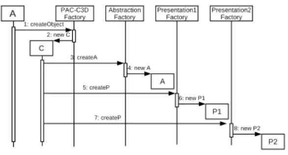
5.5 Creation of the shared virtual objects
To ensure an easy evolution of a CVE, we must use the Abstract
Factorydesign pattern (GoF87) [15] for object creation. This de-sign pattern makes it possible to let the Abstractions create new ob-jects without any knowledge of collaboration by asking an abstract factory to create these objects. The real instance of this abstract factory, called PAC-C3D factory, will deliver Controls (which are
Proxiesof their Abstraction) instead of Abstractions.
In the same way, the Controls must use several factories in order to create their associated Abstractions and Presentations. The PAC-C3D factory will give each Control one factory for Abstraction cre-ation, and a list (which can be empty) of factories for Presentations creation, corresponding to each kind of existing Presentation on its node. If allowed by its distribution policy, then the Control will ask the Abstraction factory to create a real Abstraction. Next, the
Controlwill ask each Presentation factory to create a Presentation. This is illustrated figure 11 for the creation of a PAC-C3D object on one node that is hosting two kinds of Presentations.
Figure 11: Creation of the PAC-C3D facets
Then, according to its distribution policy, this Control can send a message to the other nodes of the CVE to create also local
Con-trols: each local PAC-C3D factory will allow the creation of a local
Controlwith the appropriate set of local Presentations.
6 ADAPTATION TO DIFFERENT REPRESENTATIONS
As our model offers great independence between the facets of each PAC-C3D object, it makes it easy to provide several kinds of
Pre-sentationsfor a same virtual object.
First, for each distribution mode, the Controls can be associated to different kinds of Presentations, dedicated to a particular visual-ization of the shared virtual environment. For example, with
Con-trolswritten in Java, on one node the Presentation could rely on Java3D [2] while on another node it could rely on JMonkey [4] or jReality [5]. As the implementation details of the 3D graphics API are encapsulated within the Presentations, for example it is also possible to use any C++ 3D graphics API without perturbing
Ab-stractionsand Controls.
To avoid code duplication, all the code relative to high-level in-teraction with virtual objects should be removed from the
Presenta-tionsand written once in some Abstractions of PAC 3D interaction tools. But for an optimal efficiency, it is also possible to use built-in interaction and navigation metaphors that come with a 3D viewer.
Several kinds of Presentations can also be associated with the same Control in order to provide several representations of a shared virtual environment to a user. Some of these representations can also be a 2D visualization of the CVE. This can be extended to any kind of presentation, which could be non-visual, as a sound or a physical representation.
To benefit fully from “active” Presentations such as physics en-gines (for example they can react to an update because of colli-sion detection when trying to move a 3D object), the behavior of the PAC-C3D Controls should be slightly adapted, otherwise the “naive” use of such engines could introduce more latency and some
small inconsistencies on other Presentations in the worst situation about distribution (when the physical Presentation is not on the same node than its associated Abstraction)(see figure 12)). This adaptation could consist in updating first the “active” Presentations and taking their results into account before updating the “passive”
Presentations.
Figure 12: “Naive” use of a physics engine
7 PAC-C3DIMPLEMENTATION EXAMPLES
In this section we will make a short point about the current imple-mentations of PAC-C3D, then we will illustrate this model through 3 examples, in the context of the Collaviz framework [13, 1]. The first one explains in details how PAC-C3D can help the designer of a new 3D collaborative visualizer to reuse existing interaction tools. The second one describes more generally how PAC-C3D has been used to design the IIVC concept. The third one describes how PAC-C3D allowed us to integrate a physics engine within the Collaviz framework.
7.1 Current implementations of PAC-C3D
The first implementation of our model is dedicated to student VR projects and has already been used for two years. This simple im-plementation has been made with Java3D [2] and JMonkey [4] as 3D rendering engines, and implements only the referent and proxy distribution policies, with migration capabilities. The proxy distri-bution policy uses Java RMI for communication with its referent, and the referent distribution policy uses Multicast facilities to com-municate with its proxies Controls.
The second implementation is dedicated to industrial collabora-tive scientific visualization, it has been implemented in the context of a collaborative project called Collaviz [13, 1]. It relies on both Java3D (for desktop visualization) and jReality (for desktop and immersive visualization) as illustrated figure 1. The Controls can use the three distribution policies, and these distribution policies use either TCP or HTTP for communication [19]. All these distri-bution policies can be changed at run-time. This implementation has also been coupled to the JBullet [3] Physics Engine which ap-pears as another Presentation associated to some Controls of the system.
7.2 The 2DPointer/3DRay
Here is a full example of the benefits to use our model that shows the complementarity of the PAC-C3D separation between abstraction and presentation and of the PAC-C3D collaboration through the controls. This exemple is the implementation of the 2DPointer/3DRay metaphor [14]: a 3D ray for 3D selection and interaction which orientation is computed so that the user always sees this 3D ray as a 2D pointer on the screen, to be used as easily as a classical 2D pointer, but to be seen as a 3D ray by the other users of the shared virtual environment.
We first implemented this 2DPointer/3DRay metaphor in our Java3D visualizer, this cursor was driven with mouse events pro-vided by Java3D. We took care to clearly separate the behavior of the 2DPointer/3DRay (the computation of its orientation according
to its position, that has been isolated in an abstraction component) from the Java3D presentation code in charge of the Java3D mouse events and of the 3D picking for object selection. As a first result, this 2DPointer/3DRay can be driven by any other input device able to provide a position, for example a wiimote or an ART tracking device (see figure 13)).
Figure 13: Driving the same abstraction with different input devices
Then, we worked with jReality to provide another 3D viewer, mainly dedicated to immersive visualization devices such as work-benchs or CAVE. As this viewer was not first dedicated to desktops, we did not want to waste time to write a small presentation compo-nent able to deal with mouse events, which would be useless for immersive situations as we would use an ART tracking system for interaction. But for testing this new jReality visualization compo-nent, some work had to be done in desktop mode, and some inter-action could be useful. We decided to use the 2DPointer/3DRay metaphor driven by a wiimote (see figure 14).
Figure 14: Visualizing an abstraction with another 3D API
Once the 2DPointer/3DRay metaphor was driven by a wiimote within our jReality visualizer, the only remaining problem was to allow this metaphor to select and manipulate 3D objects. The more natural solution was to enable a 3D picking service in jReality.
If such a picking service could not have been realized with jReality, we could also have enabled the 3D picking thanks to our Java3D visualizer. As PAC-C3D has been used to design the Collaviz framework architecture, the Collaviz system allows to share a virtual environment between several visualizers, so it is possible to instantiate a Java3D visualizer and a jReality visual-izer to share a common virtual environment. The abstraction of the 2DPointer/3DRay interaction metaphor of the jReality Visual-izer can be instantiated on the process of the Java3D visualVisual-izer, that owns also a control component and a Java3D presentation compo-nent for this metaphor, while the process of the jReality visualizer owns only a proxy control and a jReality presentation component for this metaphor. As illustrated figure 15, this distribution mode would allow the proxy control on the jReality side to send the pick-ing request to the referent control on the Java3D side, which would
be able to achieve the picking thanks to the 3D picking service of the Java3D visualizer.
Figure 15: Delegating behavior to abstraction and other presentation
7.3 Other interaction and navigation tools
The whole architecture of our 3D visualizers is designed thanks to the PAC-C3D model, this enables us to provide a common architec-ture for navigating and interacting within 3D virtual environments that we call the Immersive Interactive Virtual Cabin (IIVC) [18]. All the operators that have been proposed for this IIVC (such as dedicated navigation modes or interaction tools) are implemented within abstraction components linked to dedicated presentation in charge of the visualization of their actions upon the virtual environ-ment through control components.
It makes it possible to use the same input devices (for example a 2D GUI or a joystick) for navigation whatever the 3D graphics API is used for a 3D visualizer: the navigation orders are sent to the abstraction of what we call a “conveyor”, which supports several virtual objects including a virtual viewpoint, which position and orientation are changed whenever the conveyor moves in the world. These changes occur in the abstraction of the virtual viewpoint, then its control component is in charge of propagating these changes to its associated local presentation component and to its distributed controls if any.
Figure 16: Delegating navigation to the abstraction of a viewpoint
Figure 16 illustrates these local exchanges with the camera of a 3D visualizer: the position and orientation changes of the conveyor are sent to the abstraction of the virtual viewpoint, which can com-pute its own new position and orientation before sending them to its presentation through its control component. The presentation of the virtual viewpoint can be linked to the camera of a 3D visualizer, which impacts the rendering of the 3D visualizer.
So, any particular way of navigation (for example a “travelling” along some interesting object, or an “examine” navigation mode allowing to turn around a virtual object, or a “walk” or a “fly” nav-igation mode allowing different kinds of exploration of a virtual environment) has only to be coded once, in the abstraction of the conveyor, to be available for any 3D visualizer, whatever the 3D graphics API used.
In the same way, a conveyor can support any 3D interaction tool (such as our 2D pointer / 3D ray, or classical 3D virtual rays, virtual hands or virtual 3D cursors), and here again these interaction tools offer the same behavior whatever the 3D graphics API used.
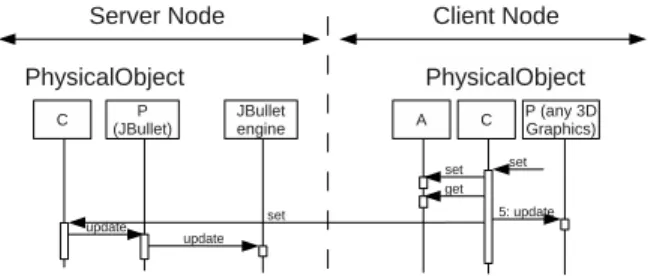
7.4 Coupling a physics engine to a virtual environment
To make collision detection possible within our 3D visualizers, we chose to integrate the JBullet Physics Engine [3] into the Collaviz framework. The most straightforward way to achieve this is to place the JBullet engine component on the central collaboration server process, in order to be able to provide the physics services (for ex-ample collision detection or mechanical constraints) in the same way to any Visualizer client. Otherwise, this JBullet component could be placed on any node of the shared virtual environment. So, for any virtual object for which we want to offer physics, we declare it as a physical object, with an additional JBullet presentation com-ponent, linked to the JBullet engine. Each move of the virtual object in the virtual environment will make its physical JBullet presenta-tion move in the JBullet world (see figure 17), which will allow to take into account the results (collision or constraints) provided by the JBullet engine, as already presented figure 12.
Figure 17: Maintaining consistency between Virtual and Physical worlds
Once again, this allows to offer physics for the objects of the virtual universe whatever the 3D graphics API used for the 3D Vi-sualizer: We have implemented generic physical 3D cursors that behave exactly in the same way in our two main visualizers, based on Java3D and jReality.
8 CONCLUSION ANDFUTUREWORK
The PAC-C3D architectural model is an explicit evolution of the PAC model dedicated to 3D collaborative virtual environments. Each shared virtual object of a CVE must be decomposed into three main kinds of components described by three interfaces. The
Ab-stractionis in charge of the core data and behavior of the object, the Presentations are in charge of the presentation of the object to the user, and the Control is in charge of the consistency mainte-nance between Abstraction and Presentations, and between all the distributed Controls of the shared object.
PAC-C3D can deal with the main distribution modes encoun-tered in CVE and it has been validated with several distribution policies, on local area networks and on wide area networks over the internet.
PAC-C3D also makes it possible to design a CVE with very small dependency on a 3D graphics API, and it makes it easy to use dif-ferent 3D graphics API for difdif-ferent nodes involved in the same collaborative session, providing easy interoperability between 3D graphics API. It is also possible to rapidly couple other 3D engines (for example physics engines) by adding another Presentation (re-lated to the engine) to PAC-C3D objects.
The next steps are to take explicitly into account “active”
Presen-tationsand to couple PAC-C3D objects with other kinds of engines, for example Artificial Intelligence behavior libraries that could be used in the same way as a physics engine to drive virtual objects.
ACKNOWLEDGEMENTS
This work was partly funded by the French Research National Agency project named Collaviz (ANR-08-COSI-003-01).
REFERENCES
[1] The Collaviz website. http://www.collaviz.org/. [2] The Java3D website. http://java3d.java.net/. [3] The JBullet website. http://jbullet.advel.cz/. [4] The JMonkey website. http://jmonkeyengine.org/.
[5] The jReality website. http://www3.math.tu-berlin.de/jreality/. [6] G. Calvary, J. Coutaz, and L. Nigay. From Single-User Architectural
Design to PAC*: a Generic Software Architecture Model for CSCW. In Proceedings of CHI 97, ACM publ, pages 242–249, 1997. [7] J. Coutaz. PAC: An Object Oriented Model for Implementing User
Interfaces. SIGCHI Bull., 19(2):37–41, 1987.
[8] C. Cruz-Neira, D. J. Sandin, and T. A. DeFanti. Surround-screen projection-based virtual reality: the design and implementation of the cave. In Proceedings of SIGGRAPH’93, pages 135–142, New York, NY, USA, 1993. ACM.
[9] M. Davis. Struts, an open-source MVC implementation. http://www.ibm.com/developerworks/library/j-struts/, february 2001. [10] D. Delaney, T. Ward, and S. McLoone. On consistency and network
latency in distributed interactive applications: A survey – part I.
Pres-ence: Teleoperators and Virtual Environments, 15(2):218–234, 2006. [11] D. Delaney, T. Ward, and S. McLoone. On Consistency and Network Latency in Distributed Interactive Applications: A Survey – Part II.
Presence: Teleoperators and Virtual Env., 15(4):465–482, 2006. [12] P. Dewan. Architectures for Collaborative Applications. Trends in
Software, special issue on Collaborative Systems, pages 169–193, 1999.
[13] F. Dupont, T. Duval, C. Fleury, J. Forest, V. Gouranton, P. Lando, T. Laurent, G. Lavou´e, and A. Schmutz. Collaborative Scientific Vi-sualization: The COLLAVIZ Framework. In JVRC Demos, 2010. [14] T. Duval and C. Fleury. “An asymmetric 2D Pointer/3D Ray for 3D
interaction within collaborative virtual environments”. In Proceedings
of the Web3D’09 conference, pages 33–41, 2009.
[15] E. Gamma, R. Helm, R. Johnson, J. Vlissides. Design patterns:
Ele-ments of reusable Object-Oriented Software. Addison-Wesley, 1995. [16] R. Eckstein. Java SE Application Design With MVC.
http://www.oracle.com/technetwork/articles/javase/mvc-136693.html, march 2007.
[17] C. Ellis and J. Wainer. A conceptual model of groupware. In
Proceed-ings of the 1994 ACM conference on Computer supported cooperative work, CSCW ’94, pages 79–88, New York, NY, USA, 1994. ACM. [18] C. Fleury, A. Chauffaut, T. Duval, V. Gouranton, and B. Arnaldi.
A Generic Model for Embedding Users’ Physical Workspaces into Multi-Scale Collaborative Virtual Environments. In Proc. of ICAT, pages 1–8, 2011.
[19] C. Fleury, T. Duval, V. Gouranton, and B. Arnaldi. A New Adaptive Data Distribution Model for Consistency Maintenance in Collabora-tive Virtual Environments. In Proc. of JVRC, pages 29–36, 2010. [20] C. Fleury, T. Duval, V. Gouranton, and B. Arnaldi. Architectures and
Mechanisms to efficiently Maintain Consistency in Collaborative Vir-tual Environments. In Proc. of the 3rd IEEE VR 2010 Workshop on
Software Engineering and Architectures for Realtime Interactive Sys-tems (SEARIS 2010), pages 87–94, 2010.
[21] A. Goldberg. Information models, views, and controllers. Dr. Dobb’s
J., 15:54–61, May 1990.
[22] Y. Laurillau and L. Nigay. Clover architecture for groupware. In
Proceedings of the Conference on Computer-Supported Cooperative Work, pages 236–245. ACM, 2002.
[23] M. R. Macedonia and M. J. Zyda. A taxonomy for networked virtual environments. IEEE Multimedia, 4(1):48–56, Jan-Mar 1997. [24] L. Nigay and J. Coutaz. Building User Interfaces: Organizing
Soft-ware Agents. In Proceedings of Esprit’91, pages 709–717, 1991. [25] M. Potel. MVP: Model-View-Presenter — The
Taligent Programming Model for C++ and Java. http://www.wildcrest.com/Potel/Portfolio/mvp.pdf, 1996.
[26] T. Reenskaug. The original MVC reports. http://heim.ifi.uio.no/˜trygver/2007/MVC Originals.pdf, 1979. [27] . UIMS 1992. A metamodel for the runtime architecture of an
in-teractive system: the uims tool developers workshop. SIGCHI Bull., 24(1):32–37, 1992.