1
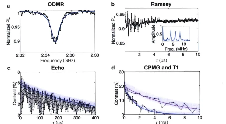
Coherent Control of Nitrogen-Vacancy Centers in Diamond
Nanostructures For Quantum Sensing and Networking
by
Edward H. Chen
B.S. in Physics, California Institute of Technology (2010)
M.S. in Applied Physics and Applied Mathematics, Columbia University (2011) Submitted to the Department of Electrical Engineering and Computer Science
in partial fulfillment of the requirements for the degree of Doctor of Philosophy
at the
MASSACHUSETTS INSTITUTE OF TECHNOLOGY
Author
September 2016
@Massachusetts
Institute of Technology 2 6. All rights reserveSignature redacted
De 'nt Certified by ... Accepted by ... OF TECHNOLOGYS EP 2
8
2016
LIBRARIES
ARCHIVES
of &M-rrical Engineering and Computer Science August 22, 2016
Signature redacted
Dirk R. Englund Jamieson Career Developm nt Assistant Professor of Electrical gineerin and Computer Science Thesis SupervisorSignature redacted
C)
0 Uslie A. Kolodziejski Professor of Electrical Engineering Chair, Department Committee on Graduate StudentsCoherent Control of Nitrogen-Vacancy Centers in Diamond
Nanostructures For Quantum Sensing and Networking
by
Edward H. Chen
Submitted to the Department of Electrical Engineering and Computer Science on August 22, 2016
in partial fulfillment of the requirements for the degree of Doctor of Philosophy
Abstract
The exceptional optical and spin properties of the negatively charged nitrogen-vacancy (NV-) center in diamond have led to numerous applications ranging from super-resolution imaging to the exploration of previously untested new phenomena using quantum entan-glement for information processing and sensing. The solid-state environment of the dia-mond allows us to engineer nanostructures, which are promising for enhancing the optical and spin properties of the NV-. To help develop a component needed for a diamond-based quantum network, we recently achieved coherent electron spin control of long-lived NV-s in diamond nanostructures using a transferrable hard-mask for both etching and ion implantation. We also developed a super-resolution imaging technique for character-izing such systems, and we furthermore demonstrate high-sensitivity electrometry using a large number of NV-s. However, it remains an open area of investigation whether certain nano-fabrication processes for patterning nanostructures into diamond cause ir-recoverable damage or introduce atomic impurities to the crystal that would lead to a significant degradation of the NV- properties. Another remaining challenge is to pro-duce fault-tolerant multi-qubit registers within nanostructures for improved robustness and scalability for use in compact quantum sensors or quantum networks. By building on the results in this thesis, it may be possible to design nanostructures for enhancing initialization, control and read-out fidelities of defect-based solid-state quantum technolo-gies.
Thesis Supervisor: Dirk R. Englund
Title: Jamieson Career Development Assistant Professor of Electrical Engineering and Computer Science
Citations to Previously Published Work
Papers are listed in the order they are introduced.
" L. LI*, T. SCHR6DER*, E. H. CHEN*, M. WALSH, I. BAYN, J. GOLDSTEIN,
0. GAATHON, M. E. TRUSHEIM, M. Lu, J. MOWER, M. COTLET, M. L.
MARKHAM, D. J. TWITCHEN, AND D. ENGLUND, Coherent spin control of a nanocavity-enhanced qubit in diamond, Nature Communications, 6 (2015), p. 6173
" L. LI*, E. H. CHEN*, J. ZHENG, S. L. MOURADIAN, F. DOLDE, T. SCHR6DER,
S. KARAVELI, M. L. MARKHAM, D. J. TWITCHEN, AND D. ENGLUND, Efficient
Photon Collection from a Nitrogen Vacancy Center in a Circular Bullseye Grating, Nano Letters, 15 (2015), pp. 1493-1497
" I. BAYN*, E. H. CHEN*, M. E. TRUSHEIM*, L. Li, T. SCHR6DER, 0. GAATHON,
M. Lu, A. STEIN, M. Liu, K. KISSLINGER, H. CLEVENSON, AND D.
EN-GLUND, Generation of Ensembles of Individually Resolvable Nitrogen Vacancies
Using Nanometer-Scale Apertures in Ultrahigh-Aspect Ratio Planar Implantation
Masks, Nano Letters, 15 (2015), pp. 1751-1758
" E. H. CHEN, 0. GAATHON, M. E. TRUSHEIM, AND D. ENGLUND, Wide-field multispectral super-resolution imaging using spin-dependent fluorescence in nanodi-amonds, Nano Letters, 13 (2013), pp. 2073-2077
" E. H. CHEN, K. A. JOHNSON, L. M. PHAM, H. A. CLEVENSON, D. R.
EN-GLUND, P. R. HEMMER, AND D. A. BRAJE, High-sensitivity electrometry with an
ensemble of nitrogen-vacancy centers in diamond, In Preparation, (2016)
" S. I. KNYSH, E. H. CHEN, AND G. A. DURKIN, True Limits to Precision via Unique Quantum Probe, arXiv:1402.0495 [math-ph, physics:quant-ph], (2014)
Acknowledgements
I would like to acknowledge the support and guidance of my supervisor, Dirk Englund, and our collaborator, Danielle Braje. I am indebted to them for investing in me during my most formative years of development as an aspiring scientist. I am grateful that my mentors had the ability and foresight to undertake research of nitrogen-vacancy centers (NV-s) over a dizzyingly broad range of topics even amidst, what seemed to be, the exponentially growing world-wide interest in the field. The wide exposure provided me with a unique opportunity to engage in physics and engineering from many different perspectives, and I am certain that this multi-disciplinary attitude towards conducting research will pay dividends throughout my career. I am especially thankful to Dirk for relentlessly setting high expectations in all aspects of research - from demanding succinct writing and impressionable presentations, to being endlessly inquisitive in every scientific discussion. I am also very thankful to Danielle for agreeing to take over the responsibility of being my NASA advisor in the third year of my fellowship, and for trusting me to undertake my own directions for sensing electric fields with NV-s in her lab. I look forward to maintaining a life-long working relationship with them, and to eventually honor their efforts by mentoring future generations of scientists.
I would also like to thank my committee members, Paola Cappellaro and Marc Baldo. In particular, Paola for her precious time in guiding me with her insights of spin physics, and Marc for providing reliable and constructive advice at the beginning of every semester. The staff working tirelessly behind the scenes were also indispensable in creating a stimulating research training experience. Those people include: Dina Amin, Zachary Collins, Montserrat Fernandez-Pinkley, Chammali Josephs and Columbia University; Jan-ice Balzer, Alicia Duarte, Janet Fischer, David Foss, William Gibbs, Tina Gilman, Al McGurl, Bill Adams and MIT; and Claudia Meyer and her team at NASA's office of chief technologist office.
Without my exceptional co-authors, I would not have been nearly as productive in my research endeavors: Igal Bayn, Luozhou Li, Tim Schr6der, and Matthew Trusheim. They have kept the research exciting both inside and outside of the lab, and I look forward to continuing to work with them. I also learned a great deal of useful skills from my officemates over the years: Ashish Banerjee, Jacob Mower, Matthew Trusheim, Catherine Lee, Greg Steinbrecher and Nicholas Harris. Other co-authors and labmates that were vital to my research experience include: Jonathan Hodges, Ophir Gaathon, Sergio Allegri, Noel Wan, Ren-Jye Shiue, Xuetao Gan, Chaitanya Rastogi, Xinwen Yao, Hannah Clevenson, Pierre Desjardins, Jiabao Zheng, Sara Mouradian, Abraham Wolcott, Reyu Sakakibara, Ming Lu, Hassaram Bakhru, Aaron Stein, Kim Kisslinger, Gabriel Durkin, Sergey Knysh, Jordan Goldstein, Carson Teale, Sinan Karaveli, Mikkel Heuck, Florian Dolde, Gabriele Grosso, Dimitri K. Efetov, Kwang-Yong Jeong, Kerry Johnson, Linh Pham, John Barry, Philip Hemmer. Finally, I would like to thank the younger,
Contents
up-and-coming students in the research groups for bringing so much enthusiasm to the lab every day: Christopher Foy, Michael Walsh, Donggyu Kim, Hyeongrak Choi, Ben Lienhard, Darius Bunandar, Cheng Peng, Mihika Prabhu, Eric Bersin, Erik Eisenach, Mihir Pant, Tsung-Ju Lu, Hyowon Moon, Maarten Degen, Scott Alsid, and Christopher McNally.
I would also like to acknowledge a number of inspirational faculty who have played a significant role in shaping my research interests over the years: Daniel Kleppner, Yoel Fink, Steven G. Johnson, James Fujimoto, Karl Berggren, Isaac Chuang from MIT; Gil Refael, John Preskill, Frank Porter, H. Jeff Kimble, and Nai-Chang Yeh from Caltech.
I will never be able to thank my family enough for their unconditional support and love. I am indebted to the sacrifices my parents made as the stereotypical hard-working and proud first-generation American citizens. I am especially grateful for the strong work ethic they instilled in me. I must also thank my brother who is always inspiring me to be a more considerate and thoughtful person. Most importantly, I must thank Noele Norris for being the most brilliant, loyal, and principled person in my life. I am also incredibly lucky that her parents and sister are also such wonderful and loving people. Most of all, I look forward to overcoming new challenges and sharing the joyful moments in life together with Noele, my best friend.
Contents
Abstract
Citations to Previously Published Work ii
Acknowledgements
iii
1 Introduction 1
2 The nitrogen-vacancy center in diamond 5
3 Coherent spin control of a nanocavity-enhanced qubit in diamond 13
3.1 Introduction . . . . 13
3.2 Photonic Crystal Simulation and Optimization . . . . 15
3.3 Experimental Results . . . . 15
3.3.1 Diamond Fabrication . . . . 15
3.3.2 Nanofabrication using silicon masks . . . . 17
3.3.3 Optical characterization . . . . 19
3.3.3.1 Experimental setup . . . . 19
3.3.3.2
#-factor
estimation . . . . 223.3.3.3 Spontaneous emission lifetime change . . . . 23
3.3.3.4 Low-temperature gas tuning . . . . 23
3.3.4 Spin measurements . . . . 24
3.3.4.1 Electron Spin Coherence (T2) . . . . 24
3.3.4.2 Spin-Lattice Relaxation (Ti) . . . . 25
3.4 D iscussion . . . . 26
4 Broadband fluorescence collection from single NV-s 29 4.1 Introduction . . . . 29
4.2 Nanostructure Design . . . . 30
4.3 Sam ple Preparation . . . . 31
4.4 Experim ental Setup . . . . 31
4.5 Optical Characterization . . . . 32
4.5.1 Spectrum of an NV- inside the circular grating . . . . 34
Contents
4.5.3 Influence of background emitters . . . . 4.5.4 Additional saturation curve analysis . . . . 4.6 Spin Characterization . . . . 4.6.1 Spin Normalization Sequence . . . . 4.7 D iscussion . . . . 5 Generation of Ensembles of Individually Resolvable Nitrogen Vacancies
Using Nanometer-Scale Apertures in Ultrahigh-Aspect Implantation Masks Ratio Planar 5.1 Introduction . . . . 5.2 Implantation Technique . . . . 5.3 R esults . . . . 5.3.1 Mask Creation . . . . 5.3.2 Mask Characterization . . . . 5.3.3 Nitrogen Implantation . . . . 5.3.4 Super-resolution characterization . . . . 5.4 M ethods . . . . ... . 5.4.1 Cross-section preparation . . . . 5.4.2 TEM sample preparation . . . . 5.4.3 NV- Localization . . . .. . . . 5.4.4 NV- Distribution Characterization . . . . 5.5 Discussion . . . . 6 Wide-field multispectral super-resolution imaging using spin-dependent
fluorescence in nanodiamonds 6.1 6.2 6.3 6.4 6.5 6.6 6.7 Introduction . . . . NV- Control . . . . W hy Nanodiamonds? . . . . Theoretical Limits . . . . Confocal Results . . . . W ide-field Results . . . . Discussion . . . .
7 Electric-field sensing with ensembles of NV-s
7.1 Introduction . . . . 7.2 Theory of NV- electrometry . . . . 7.3 Experimental Results . . . . 7.4 M ethods . . . . 7.4.1 Full energy transition expression . . . . 7.4.2 Zero-ing of magnetic field using gradient descent . . 7.4.3 Digital Lock-In Amplifier Implementation . . . . . 7.4.4 Excited-state optically detected magnetic resonance 7.5 D iscussion . . . . 43 43 44 46 46 48 49 52 52 54 54 55 55 58 61 61 62 64 64 65 66 68 69 69 70 73 75 75 77 78 79 80 viii 36 37 39 41 41
Contents
8 Conclusion 83
8.1 How far have NV-s come? . . . . 83 8.2 Milestones of NV-s in nanostructures . . . . 84 8.3 Outlook for an NV--based quantum network . . . . 85
A Optical Rate Equation Model 87
A.1 Rate equation analysis . . . . 87 B Details of Deterministic Emitter Switch Microscopy 91 B.1 Rate equation analysis . . . . 91
"Der Mensch kann tun was er will; er kann aber nicht wollen was er will."
"Man can do what he wills but he cannot will what he wills."
Chapter 1
Introduction
Building a large-scale quantum network connected via photons is currently an outstand-ing problem within the atomic, molecular and optics community. Such a network of connected quantum nodes is a prerequisite for realizing quantum-based metrology, com-munication and computation protocols that promise fundamental improvements in sen-sitivity, security and speed over their classical counterparts. The dimension of the state-space of a quantum network grows exponentially with the number of connected nodes, while for a classical network th6 dimensionality grows linearly with the num-ber of connected nodes [87, 110]. Therefore, a quantum network consisting of thou-sands of connected nodes would surpass the dimensionality of any existing classical net-work [188]. Since the first theoretical proposal for building a large-scale, fault-tolerant quantum network by Cirac, Zoller, Kimble and Mabuchi in 1997 [47], much research has sought to develop the individual components needed for assembling a quantum net-work [27, 28, 36, 78, 124, 152, 213, 265].
Although experimental progress in the past decade has been impressive, entanglement generation rates remain below the threshold needed for a practical network, and the first realization will likely involve a combination of technologies [75, 185]. Currently, the leading candidates for a quantum network include trapped ions [97, 168], solid-state spins [158], Rydberg atoms [105], and superconducting systems [14]. As of 2015, the fastest entanglement generation rates between two separated nodes fall in the range of once every 250 seconds between solid-state spins in diamond [181], several times per second between two separated nodes of trapped ions [96], and even -2300 times per
Chapter 1. Introduction
second between two quantum dots [50]. However, to properly compare between such a wide spectrum of different systems, the entanglement rates also need to be assessed with
respect to the decoherence rates. Among the listed candidates, spins within solid-state structures are appealing because they have sufficiently low decoherence rates and could be readily integrated with existing scalable technologies [67, 75, 185, 235].
The negatively-charged nitrogen-vacancy defect (NV-) in diamond is currently the leading candidate for utilizing solid-state spins to construct a node within a scalable quantum network [11, 40, 140, 163]. The storage of quantum states on the electron spins of the NV- center can have a spin coherence time approaching one second at cryogenic temperatures (< 15 Kelvin), which allows the distribution of entanglement between sep-arated quantum nodes via photons [13, 224, 239]. In addition to having long coherence times, the diamond environment can be patterned with nanostructures to further enhance the NV- properties. Such enhancements include: modifying the local density of states of electromagnetic fields for optical communication applications; engineering high optical collection gratings for sensing applications; and modifying the local phononic density of states.
The diamond nanostructures considered in this thesis represent our efforts to enhance the NV-'s optical properties. By patterning high-quality optical cavities into diamond, we show that it is possible to improve currently achievable NV--NV- entanglement rates by a factor of 800, which makes the NV- even more attractive when compared with trapped ions and quantum dots. Additionally, by pattern gratings around single NV-s we show that it is possible to enhance the read-out fidelity of shallow NV-s by nearly 10-fold, which further establishes NV-s as the premier nano-MRI tool. In seeking to enhance the capabilities of such nanostructures, we also developed new fabrication methods for including multiple spins within each nanostructure while also having at least one spin within the nanostructure efficiently coupled with an optical mode for efficient read-out. While breakthrough experiments have already been demonstrated with the NV- [40, 77, 130, 258], we anticipate a need for further breakthroughs in producing NV-s with pristine optical quality inside nanostructures that can be actively tuned in-situ before we can realize a multifunctional, scalable light-matter interface for widely-used quantum applications.
Chapter 1. Introduction
This thesis begins with a brief introduction to the physics of the NV- in Chapter 2. Chapter 3 introduces a hard-mask fabrication technique for patterning high-quality pho-tonic crystal cavity nanostructures into diamond while preserving the NV- electronic spin properties. Chapter 4 shows that a grating nanostructure can be used to increase the photon collection from a single NV- while again preserving the spin properties. Chap-ter 5 shows that the same hard mask used for etching can also be used as an implantation mask for generating ensembles of NV- spins. Chapter 6 shows how a deterministically switching emitter super-resolution microscopy technique can be used to control the fluo-rescence of NV-s separated by tens of nanometers. Chapter 7 shows how ensembles of NV-s can be effectively applied to sensing electric fields. Finally, Chapter 8 provides an outlook for where NV- spins in diamond nanostructures might be most impactful in the near future.
Chapter
2
The nitrogen-vacancy center in
diamond
To understand how the optical and spin properties of the NV- are utilized in our work, it is important to briefly describe the underlying physics [52]. The color center, commonly known as the NV- center, is comprised of a vacancy of one carbon atom in the carbon lattice with an adjacent nitrogen atom (See Fig. 2.1a). The NV- resembles, in many ways, a trapped ion due to its well-defined energy levels, which arises from the interaction of the six valence electrons that comprise the NV-. The origin of the six electrons is as follows: three electrons from the three adjacent carbons, two electrons from the host nitrogen, and a final electron introduced from the conduction band of the diamond lattice [122]. These six valence electrons are missing another two electrons to completely fill the sp3 molecular orbital. So rather than working with a six-electron wave function, one can understand the spin physics by considering an equivalent two-hole wave function. Figure 2.1 depicts the diamond lattice in which the two-hole wave function presides. It is precisely the sum of two these spin-1/2 holes that gives rises to the addressable triplet (S = 1) ground and excited state configurations of the NV-. These states are labelled as m, = 0, I in both the excited and ground states, and it is the coherence between these spin states that is most often touted and utilized throughout our work.
To understand how to control and read out the NV- with electromagnetic fields, it is important to understand the symmetries underlying the NV-. The NV- has trigonal symmetry, lying along along the vacancy-nitrogen direction. The nitrogen-vacancy bond
Chapter 2. The nitrogen-vacancy center in diamond
lies along the axis of highest symmetry for the NV- and is also the spin quantization axis due to the strong crystal field induced by the spin-spin interactions of the electrons. Given that any NV- has its quantization axis set by the crystal lattice, a single-crystalline diamond samplea would then have up to eight possible orientations of NV-s within the lab frame. For a single NV-, the magnetic dipole of the S = 1 triplet lies along the NV- 's axis of highest symmetry while the two optically addressable and emissive electric dipoles lie perpendicular to that axis.
The spin configurations (m8=0,t1) of the ground state can be read out by a
vari-ety of optical techniques [52, 214. The most common method involves an incoherent excitation of the NV- with a 532 nm, green laser. Following an optical excitation, the NV-photoluminescences (PL) at wavelengths from 637 nm to 760 nm (considered 'red' in color). Interestingly, incoherent optical excitation is only possible due to the presence of thermal phonons in the lattice. This ladder of harmonic vibrational states between the carbon nuclei decays with time scales of picoseconds. So using a laser to incoherently excite an NV- alters the electronic configuration, which temporarily changes the inter-nuclei distances. Upon relaxation of the electronic configuration, phonons are introduced into the lattice. Following the phonon relaxation, the electronic spins occupy the Lowest Unoccupied Molecular Orbital (LUMO) configuration. This electron state decays and ra-diates to the ground state via zero, single or multiple phonon scattering processes. Purely radiative processes that do not produce phonons in the lattice give rise to the highest energy optical emission at 637 nm, which is referred to as the zero-phonon line (ZPL) in the PL spectra. The blue gradient in Figure 2.1b illustrates the phonon density-of-states with which the electronic molecular orbitals can interact, thereby giving rise to a phonon side-band (PSB) in the PL spectra (See Fig. 2.2).
When the ground state spin is in the m,=0 spin state, an optical excitation would abide by spin selection rules and the resulting optical excited state will retain the m,=0 spin state with a high probability. Moreover, the emission from this excited state will decay back to the m8=0 ground spin state with - 99% probability (a value that varies
depending on the temperature and strain of the NV- [187]). When the ground state spin is in the m,= l configuration, an optical excitation can populate the m8= l excited spin states of the NV-again due to selection rules. However, unlike the m,=0 excited states, there is a ~ 50% probability that the electrons will non-radiatively populate a long-lived aA single-crystalline sample is one that maintains its translational symmetry throughout the sample.
Cliapter 2. The nitrogen-vacancy center in diailionld
I
6 electrons, modeled os 2 holes Crystal Fie Splitting QZFS...
990% >637 nm, T~12ns Orbital Strain Splitting *mj=f1 . yIms= 0>
E
spin -orh
eie50% 50% able state OOns) 0%.- 70%
C.
I-0
0 500 1000 15d.
0.98 DZFs 0.96a -~ms -1:jms=+1
AO94 o 2000 2500 3000 Time (ns) 2.85 2.9 Frequency (GHz) 2.95FiRE 2. 1: a. Illustration of tle nit rogeit-vacancy defect within ithe dialioin d lattice
of carbons (black). b. and c. NV- eiergy level diagram showiiig how prefereiitial
shelving of the = 1) excited states (E) into the dark nietastale state gives rise to a typical spini-depei(leit fluorescence (see 1 c.) [136]. The relative brancliig ratios are highly depenidelit oii the teIperiiatr ile d straili eiiviroiwit. but the approxiiate
values are nontetheless shown to provide an order-of- iagnitntde estimate [52]. Additioin-ally, any strain on the NV- leads to splitting of the orbital eiinergy levels in the excited state (which is incidentally mixed with the gronid state, allowiiig for electric-field senls-big with the NV- gronid state spin). d. Fluoresceice of ani NV- in the presence of a static magnietic field as a fnction of applied microwave friequeincy. The splitting of the
two Lorentzians is given by the projection of the in cident maignetic field on the iag-netic moment of the NV- (l -B) of the triplet groud state. The contrast of each dip has aii inverted Lorentziai shape wit hi a milinininin line width limited by the dephasing
time due to the electron's magnetic or electric interactions with the enviroiiient (T2*).
0
b.
ld 532 nm metast(-2 3tcy-B
3
A
2
-"2.8
Chapter 2. The nitrogen-vacancy center in diamond
metastable singlet state, which has a lifetime of ~200 ns [255]. This spin-dependent transition is caused by the so-called intersystem crossing, which is enabled by spin-orbit coupling. Without this spin-dependent transitionb, there would be no spin-dependent fluorescence difference between the spin states and room-temperature readout of the spin states would not be possible for the NV-.
The symmetry of the NV- can be broken under applied crystal strain or electric fields, and the resulting optical excited states are split into two orthogonal dipole transitions (denoted as E., and Ey). Due to motional-narrowing by phonons [187], the spin con-figurations m8=0,t1 within the E, and Ey can become mixed. Such mixing rates are strongly strain- and temperature-dependent [76]. Across a large range of temperatures varying from 4 - 400 K, the NV- exhibits this spin-dependent PL due to the spin-orbit coupling in the excited state. The difference in PL contrast is largest within the first few hundred nanoseconds due to the lifetime of the longer-lived metastable dark state. After several tens of optical cycles' the NV- is then polarized into the m,=0 spin state. The steady-state PL falls below the peak of a fully m,=0 state due to the - 1% chance that the metastable state decays into the m,=+l spin state, which then also has again a ~ 30% likelihood of relaxing into a m,= l spin configuration (See Fig. 2.1b). Therefore the alternating possibilities between the two spin states yields a lower steady-state flu-orescence. Upon applying a continuous microwave (MW) field while sweeping the MW frequency across the crystal field splitting energy (denoted as QZFS - 2.87 GHz), the
NV- will have reduced fluorescence due to the population of the 1 spin states. The degeneracy of the 1 spin states can be lifted with an applied magnetic field by a magni-tude proportional to the dot product between the magnetic dipole (j7 d) with the applied
magnetic field,
B
(See Fig. 2.1d).The coherence and relaxation spin properties of the NV- electronic spin are largely impacted by the purity of atomic species within the diamond lattice. The ground state spin Hamiltonian that most succinctly captures the NV-'s spin properties is shown in Eqn. 2.1. The first term describes the crystal field splitting at about D~2.87 GHz; the second term is electronic Zeeman term; and finally the third term are the hyperfine interaction between the electronic spins and the host nuclear spin. Some important
bSpin-orbit coupling is a requirement for any optically addressable solid-state spin defect [75]. cApproximately calculated by taking the metastable lifetime, 200 ns, divided by the radiative lifetime, 12 ns.
Chapter 2. The nitrogen-vacancy center in diamond
perturbations to the Hamiltonian includes the interaction with other nearby electron spins in the diamond lattice through dipole-dipole interactions (Eqn. 2.2) and with other nuclear spins in the lattice through hyperfine interactions (Eqn. 2.3). Nuclear-nuclear interactions are ~1000 times smaller than even the hyperfine interactions and are therefore neglected in this thesis.
HNV oc (D + dI)Z2 + _B + _ - 1 (2.1)
Zi
oc S A I.i (2.2)#j Oc _ - -S$ (2.3)
where D is the crystal field splitting, d1i is the axial electric-field dipole moment, B is
the magnetic field vector, g is the g-factor tensor, S is the electronic spin-1 Pauli tensor,
A
is the hyperfine tensorI is the nuclear spin-1 Pauli tensor,Ai
is the hyperfine tensor of the NV- with the ith nuclear spin in the lattice, I is the ith nuclear spin's Pauli tensor, Mi is the magnetic coupling tensor of the NV-with the jth electron spin in the lattice, and 9j is thejth
electron's Pauli tensor.Due to the aforementioned interactions between the NV- and the environmental mag-netic spins, it is important to understand the initial material properties of the diamond under testing. Table 2.1 shows how the density of nitrogen spins in the lattice impact the coherence properties of the NV-'s electronic spin. If the density of impurities is ex-tremely high (-500 ppm), coherence times (T2) at room temperatures can be as low as
several microseconds. As the density of paramagnetic impurities is lowered, the coherence times improve dramatically due to a reduction in spin-spin interactions. However, the spin-relaxation time (TI), which is primarily attributed to phonons in the lattice, remains fairly robust with respect to the purity of the diamond environmente.
NV- spin properties are not only highly sensitive to nearby magnetic spins, but its optical properties are also highly sensitive to fluctuating electric fields due to the hopping of charges between nearby trap sites'. The rate at which hopping occurs is proportional to the population of charges and trap sites in the lattice. If there are nearby trap sites
eAlthough magnetic noise that is resonant with the energy splitting can also lead to a drop in T1 [115,
177].
'Commonly due to single, or multiple vacancies in the lattice, or other dopants such as boron or nitrogen (P1) lattice substitutions.
9
Chapter 2. The nitrogen-vacancy center in diamond
Nomenclature Room Temperature
Nitrogen Density T T2
Type lb ~ 500.Oppm ~ Ims - 5ts
Type Ila ~ 0.170ppm ~ 5ms ~ 250ps
Electronic Grade (EG) ~ 0.001ppm ~ 8ms - 800' s
TABLE 2.1: See [228] for Type IB, [123] for Type IIA, and [13] for EG results.
for such charges (typically photo-induced), then there will be electric-field fluctuations at the NV- leading to a fluctuation in the optical energy level due to the Stark effect. The dephasing process of the NV-'s optical emission leads to both homogeneous and inhomogeneous broadeningg. Therefore, it is clear that the ideal diamond lattice not only requires low densities of nearby paramagnetic impurities to preserve the NV-'s spin properties, but also requires low concentrations of dangling bonds to mitigate the effects of photo-induced charges on the NV-'s optical properties. Meeting these requirements is an on-going challenge because it essentially requires the deterministic creation single NV-s in the lattice without introducing any other defects in the diamond lattice.
One last important optical property is the NV-'s fraction of PL emission into the ZPL (See Fig. 2.2). Because of the high Debye temperature (-1870 Kelvin [253]) of diamond, there is not much difference in the phonon density of states between cryogenic and room temperatures. As a result, the fraction of non-phonon-mediated transitions (ZPL transitions) remains consistently around 3% [186]. Although this fraction (known as the Debye-Waller (DW) factor) is stable with respect to temperature fluctuations, its low value becomes a major hindrance for applications to large-scale quantum network which require larger fractions of coherent photon emission from the NV-. Fortunately, high-quality optical cavities had been proposed to drastically improve the DW factor [41, 42, 107], and in the past few years important demonstrations have been achieved showing that this limitation is not necessarily a problem any longer [4, 66, 108, 127].
Throughout the remainder of this thesis, many of the underlying physical mechanisms that give rise to the NV-'s optical and spin properties introduced here will be continually revisited and further clarified - specifically in the context of nanostructures for enhancing the properties of the NV- as it might be used for quantum networks and sensors.
5We consider homogeneous broadening of a single NV- to be the line-width measured for each resonant
optical scan, while inhomogeneous broadening of a single NV- characterizes the the amplitude of the spectral 'jumps' made by the optical transition from one optical scan to the next. See [45, 209] for more details.
Chapter 2. The 1itrogeni-vacanw(y ceiter Iii dialilold 1600
Zero-Phonon
1400,Line (ZPL)
1200-1000 800 15 Kelvin 50C 400 +- 300' 0.-600 650 700 750 800 Wavelength (nm)FiC :RE 2.2: Crvogenic (15 K) mid rooi (300 K) teiiperature PL spectra froni a siiigle
NV-. Notice that the fraction of emission into the ZPL remains constant (DWV factor
~0.03), but that the lilne-width of the ZPL significantly narrows at low temperatures
Chapter 3
Coherent spin control of a
nanocavity-enhanced qubit in
diamond
3.1
Introduction
The coupling between photons and quantum states of an emitter is efficient in the strong Purcell regime, in which the emitter interacts primarily with one optical mode. This regime is reached when the overall Purcell enhancement exceeds unity (F > 1) [226]. In the case of an NV-, only a small fraction of the PL is emitted via the ZPL transitions [264]. Therefore, one has to differentiate between the overall Purcell enhancement F and the spectrally-resolved spontaneous emission (SE) rate enhancement FZPL = F/DW, where
DW is the Debye-Waller factor. When the NV- ZPL is coupled to a cavity with quality factor
Q
and mode volume Vmode, the enhancement is given by1
FZPL = FZPL 1 + 4Q2(A ZPL/Acav - 1)2 (3.1)
where Fzm = 3
vm is the maximum spectrally-resolved SE rate enhance-41r n Vmode
ment [201] and p= t_ quantifies the angular and spatial overlap between the dipole moment (ps) and the cavity mode electric field (E). A high FzmpY can be realized in photonic crystal (PhC) nanocavities due to their small mode volumes [238], Vmode
Cliapter 3. CohK'rcrt spin cOtr7ol Of (Ia tani.oca(rvi1y-c'ertucd (]blflit int thon diotd a y b a w K % C hT I
d
0 = 9900 200 ... ... 765.5 766 766.5 767 Wavelength (nm)FIG uu*E 3.1: ()-ehip nitr IgeiN-valaiCY (NV)-m1oavitly systei ill diaond. a. The
di-miilid p1to1tic crystal (PliC) (avities are integrated OIl a sili11 substrate with metallic striplines for cohlrent spill ( itrol (d )ptically addressed using a ci1focl setup with 5:32 in
ctmit iou s-wavc excitaitionl and phtlmnsec fflected > 630 1111. The inset shows the NV -nanoavit, y s ystem with g the NV--imocvit Ri frequency. - the NV (y natural
spin-ta11e11s emlllission (SE) decay 1t. 1(d the cavity intensity dcctlV ratc. The NV (cinsists (f a substitutional nitrogen aomn adjacent to a vacalc~y ill the dimnlonld lattice. 1 denotes the
current t1igli the stripline. and b the PhC thickness. b. Simulated electric field intensitY
for the optillized fimidallental cavit mlode. ly The PhC lIs a width W and a lattice cstalt
varyiig frm
0.91
at Ithe c(iter to = 220 111i1 over five periods. c. Scanning electronIiiCiro-grap)hi (SEI) f a representative cavity structurc. The scalc bar is 1 min. d. Measured cavity
resonance (dots) with a quality factor Q ~ 9.900 + 200 from a Lorentzian fit (blue line).
(A/n)1. and their large quality factors. ID and 2D PhC cavities in diamond [66. 88. 194]
have reaclied Q factors of 6.000 and 3.000. and Fzp1. up to 7 and 70, respectively. However.
the only spin measurement prior to our deiminstratioin oii a Cavity-coupled NV showed a
~1 ts Babi envelope decay from an NV- hosted in a lanoiidiamonid coupled to a galliun phospli(de PliC [63]. No spin coherence measurements had beenl reported oi single
crys-tal diamoid cavities, leaving uNverified the potential of NV--cavity systems as (pantu memories. Here, we present a new fabrication scheme that elnables exceptionally long spill coherence times exceeding 200 s, record-high nanocavity quality factors near the NV- ZPL emission, as well as the demonstration of an NV- in the strong Purcell regime
with F-1 of -62. Our results experimientally validate the promise of long spil coherence
Chapter 3. Coherent spin control of a nanocavity-enhanced qubit in diamond
3.2
Photonic Crystal Simulation and Optimization
The cavities were designed using finite-difference time-domain (FDTD) simulations [61] to maximize FzpEx by optimizing the ratio of Q/Vmode. As shown in Fig. 3.2, the nanocavity is based on a suspended one-dimensional diamond PhC structure with lattice constant a, beam width w = 2.4a, and thickness h = 0.7a. A linear increase of the lattice constant from 0.9a to a in increments of 0.02a per period away from the center defines the cavity defect state. The fundamental cavity mode of the optimized structure yielded a simulated
Q
= 6.02 x 10⁵ and Vmode = 1.05(A/n)3.The cavity design was optimized with the FDTD method, using a freely available software package MEEP [174]. The structural parameters are listed in Figure 3.2. We set a = 20 units and use perfectly matched layers as absorbing boundary conditions. The fundamental transverse electric (TE)-like mode gives a resonant frequency close to a/A = 0.31. We introduce a linear relationship of the lattice constant along the x-coordinate, thus forming an optical potential well. In particular, we choose a minimum effective lattice constant of a, = 0.90a at the center of the potential well and increase it to ao = a in increments of 0.02a (Fig. 3.2b). The perturbations of the lattice constants span five periods away from the center of the cavity. We optimize the cavity by changing the hole width h, and hole length hy while keeping the same pattern of holes in the x-direction with thickness h = 0.7a and beam width w = hy/0.7. The resulting Qs are shown in Fig. 3.2c, and the local maximum Q/Vmode is achieveda with h_ = 0.55a and
hy = 2a, with
Q
= 6.02 x 10⁵ and Vmode = 1.05(/n)3.3.3
Experimental Results
3.3.1
Diamond Fabrication
In the first fabrication step, high-purity ('N < 10 ppb) single-crystal diamond plates were
grown by microwave-plasma assisted CVD and were laser cut to a thickness of ~200 pIm where the area of the starting diamond sample falls in the range of 2 mm x 2 mm. The
aThere is no guarantee that the design optimization reached a global maximum of Q/Vmode. Until recently, it is uncommon for experimentally produced nanophotonic structures to match FDTD results because it is impractical to include nanofabrication imperfections in the simulation model [1201.
Chapter 3. CohJcrent SpJi Crioro f
1
( n o cavI OC(Jlit 1- crii i,.ccd qll bit in di(Lm orid a a1 a2 a3 a4 a5 ao h w hy N=O b c 1 --- - -- ---- a~ao 0.98 a5 C 600k 0.96 a4 S~, 400k 80.940 200k 0 0.94 a3 E Z! Ok rz 0.92 a2 1 0.55 > 05 1 r 1, -- ' ' 0.5 5 0.9 10 -5 0 5 10 15 0.45 N 5 /a 2 0.4 h /aFiGuE 3.2: FDTD simulation. a. Structural parameters. a denotes the lattice constant. u tile beam width., b the thickness, h, the hole width, aid hY t he hole
length. b. Illustration of the linear cavity lattice constant profile which defines the potential well. c. Cavity
Q/VM(l(.
as the hole widths and lengths are varied. Thesweep parameter Y was hlited to below 2a to avoid inultimode operation along the .y-directi101.
plates were pre-pol ishe d down to -5 pm membranes using a cast iron scaif"t. For the
creation of NV-s. a laver of nit rogen atoms was implanted at 80 keV energy and located
~100 nin from the surfacc(. Systeim A was implanted at a dosage of 5x101() 15N cm-2 and system B at 5x1" 1N (.11-2 . The membrane was annealed in a NIT ()TF-15()(X-4
vaciunim furnace (1.5x 10 " mbar) for two hours at 850C to mobilize lattice vacancies.
which combiie with 15 N atoms to form NV- centers [155. 173]. Next, the membrane was turned over and thiuned down to -200 n using plasma etching (Oxford ICP-RIE) with a mixture of chlorine and argon gases at a etch rate of ~2 mun per hour. This recipe yielded a smooth surface (RMS < 1 nm) after 4.8 n etching. The thinned membranes generally
exhibited inhonogeneous thicknesses (100 nm to 300 nn) over hundreds of microme-ters. The membrane was divided into tens of snaller pieces (each ~ 100 .im x 100 i in
size). which were transferred onto separate silicon substrates using a polydimnethylsiloxaIie (PDMS)-tipped tungsten probe (Omniprobe PT-0001.02.01). The Si PhC masks were
de-signed and fabricated to match the thickness of each membrane so that oavity resonances "Done comnmercially by lie diamond nanufacturing comipany. Elenient 6.
(3efor implantationi rnis. we always Ise siiulations to have an estimate of the ion's stoppiiig range
within the Ittice [267]. Such simulations generally underestimate the implantat ion depth due to crudely formuilated imodihels which ilprioximate the crystalline structure of diamond as al aiorphous solid.
Chapter 3. Coherent spin control of a nanocavity-enhanced qubit in diamond
would fall near the NV's ZPL, and then transferred onto the membranes using a PDMS-tipped probe. Oxygen plasma dry etching (Trion RIE at 20 seem gas flow, 50 mTorr pressure and 100 W power) was used to transfer the pattern into the membranes. After the etch, little erosion was found on the silicon PhC masks. A tungsten probe was used to remove silicon masks from diamond membranes. Finally, an SF6 isotropic dry etch
removed the silicon underneath to suspend the cavity structures. MW striplines were produced separately on intrinsic silicon using a standard semiconductor fabrication pro-cess, followed by a lift-off step for metal deposition into the silicon trenches. Finally, the diamond devices were integrated into the MW architecture using another PDMS-tipped probe.
3.3.2
Nanofabrication using silicon masks
The cavities were patterned in high-purity single-crystal diamond using a new fabrication process that employs silicon (Si) membranes as etch masks. The diamond was fabri-cated by microwave (MW) plasma assisted chemical vapor deposition (CVD), polished to 5 im thickness, and finally thinned to -200 nm using a combination of chlorine and oxygen reactive ion etching. NV-s were created by implantation of 15N and subse-quent annealing (Fig. 3.3a). The Si masks were produced by electron beam lithography and cryogenic plasma etching (sulfur hexafluoride and oxygen) from silicon-on-insulator wafers with ~220 nm-thick device layers [129]. This resulted in high-quality masks ap-proximately 100 x 100 Lm2 in area. These were subsequently placed onto the diamond membranes using a transfer process described below (Fig. 3.3b). This Si mask transfer process enables nano-patterning without the need for resist coating onto the substrate and is compatible with sample sizes down to several tens of square micrometers. We used oxygen plasma [128] to etch the Si mask pattern into the pre-thinned ~200 nm diamond membranes (Fig. 3.3c). After mask removal, the patterned diamond membranes were transferred onto a Si chip with integrated microwave striplines (Fig. 3.3d). Because the silicon mask can be fabricated with excellent quality, thanks to the availability of ma-ture fabrication technology for this material, this process yields diamond PhCs with low surface roughness and uniform, vertical sidewalls. We observed a high yield (94 %) of cavities with resonances close to NV- ZPL in a single fabrication run, with a maximum
Q
of 9,900 200 (Fig. 3.3e). Cavity resonances spectrally lower than 637 nm are suitable---(C haptier 3. Cohrcunt spin con/rol of a nnanocawityI,- rnhan.ced qu'bit in diam.ond
m
b Simask PDMS adhesive C Oxygen nlasma d u, 20 15->10-H01
0 2,000 4,000 6,000 8,000 10,000 Quality FactorFwuCURTE 3.3: Fabricatio 1roeedre aidl cavity characterization outcome. a. NV s were cieated ~10 11111 below the surface of the diaiond IIIIembranes by imI tation of 1N atos
an1(d sIIbseqIeit aninealing at 850 C. The magnified SEM shows a -200 nrn meinb)rane. b.
Silicon (Si) masks were patterned on SO1. released. and transferred on1to diamond neinbranies. The SEM shows a patterned Si mask before transfer. The scale bar is 1 [tiil. c. Oxygen reactive (io etching was used to pattern diamond miienmbranes. The false-color SEM shows the
Si mask (purple) on diamond after oxygeuI etching. The scale bar is 1 pim. d. Patterned
diamllon)d memibranie oil nicrowave striplines for- optical and spin characterization. The SEI
shows diamnonid PlIC structures alongside metallic striplines inl Si channels. The scale bar is 5
rim. e. Distribution of cavity Q factors froim one fabrication 11 ri. 78 (blue bars) of 83 cavities showed resonances in the range of 600-770 nm. while five (red bar) showed nio resonances in this
Chapter 3. Coherent spin control of a nanocavity-enhanced qubit in diamond
for NV- ZPL coupling via gas deposition tuning while longer wavelength resonances can be blue-detuned by thermal oxidationd and oxygen plasma etching [61, 88].
3.3.3
Optical characterization
3.3.3.1 Experimental setup
We optically characterized samples at ambient and cryogenic (-18 K) temperatures using homebuilt confocal microscope setups with 532 nm continuous-wave (CW) laser excita-tion. PL imaging (Fig. 3.4a) was used to identify NV-s within cavity centers, and spectral measurements determined the separation between the NV- ZPL transitions and cavity resonances. Cavity system A (circled in Fig. 3.4a) contains a single NV-, as verified by antibunching in the second-order auto-correlation function. Fig. 3.4b and c show the initial PL spectrum of system A, showing a cavity peak (Q =1,700 300) blue-detuned from the ZPL, as well as two ZPL branches Ex and Ey. These are split by 286 GHz due to local strain in the diamond lattice [18]. As shown in Fig. 3.4b, the cavity resonance was then gradually red-shifted by gas deposition [219] to overlap with the NV- ZPL transitions, resulting in strong PL enhancements (See Sect. 3.3.3.4). To determine FZPL, a rate equation model is used to analyze the transition dynamics of the NV- center (See Appendix A). In this simplified five-level model, we account for the SE rates of the PSB transitions and the different ZPL transition rates for the on- and off-resonance cases. The zero-phonon excited state to ground state transition rates of the NV- are assumed to be enhanced by the factor FzPL. One important input parameter of our model is the frac-tion of ZPL to total intensity, quantified by the DW factor [264], which we estimate from an off-resonance spectrum to be DW= 0.028. By substituting this factor into the rate equation model, we determine FZPL of 8 (15) for transition Ex (Ey) in system A. To show that our simplified rate equation model gives a reliable prediction of FZPL, we considered a second analysis method. By comparing the ZPL intensity for coupled and uncoupled cases (Fig. 3.4c), we can determine the ZPL SE coupling efficiency into the cavity mode parameterized by a factor
#
= Ipvty/(Izpvy + IPSB), where Ipiajty is the intensity of the cavity-enhanced ZPL, and IPSB is the intensity of the PSB. This method is valid in the weak excitation limit where the low population of the excited state does not influencedSimply heating the diamond in an oxygen-rich environment at temperatures below 500 C, thereby re-moving about 1 nm of diamond per hour with 30% oxygen (159 torr) and 70% nitrogen environment [103].
Chapter 3. Coherent spin control of a nanocavity-enhanced qubit in diamond
the ratio of Itta1/Ita1, where ItotaI I~aj + IPSB is the overall PL intensity when the NV- ZPL is on resonance and Itfa = 'L + IPSB is the overall PL intensity when the NV- ZPL is off resonance. From F ~ 3/(1 -
#),
we can then deduce the increase in SE rate FZPL = F/DW = 10 (17) for the E,, (Ey) transition, yielding similar values compared to the rate equation analysis.These rate enhancements are still lower than theoretically expected, as determined by the
Q
and the TE-polarization of the cavity mode. This is because the Purcell enhance-ment depends strongly on the spatial and angular overlap, and FZPL is generally much lower than the maximum possible value, Fz''pa, especially in samples with low NV- den-sity (-1 NV- per tm2 in the case of system A). Moreover, for the {100} diamond crystal used here, the maximum Purcell enhancement is reduced to FZmpa* = cos2(35.3 )Fzaxsince 35.3' is the smallest angle between the transverse-electric (TE) cavity field and the NV- dipole (i.e., crystal) orientation. Using the rate equation model for system A, we calculate an overlap factor = FZPL/Fz'pa3 * = 0.1 (0.18) for transition Ex (Ey) indicating a factor of 1/ - 10 (6) off from the theoretically expected maximum for our cavity design
due to the non-ideal spatial and polarization overlap. The difference in between Ex and Ey is attributed to different orientations of the two orthogonal NV- dipoles with respect to the TE-cavity mode [52].
To reduce the deviation from the theoretical maximum and to investigate NV--nanocavity systems in the strong Purcell regime where more than 50% of the emission is coupled into a cavity mode, we studied another sample with the same cavity designs but with a higher density of NV-s to improve the likelihood of observing a high spatial overlap between the cavity mode and a single NV- (~10 tm-2). Fig. 3.4d shows the PL spectrum of NV--nanocavity system B with QB =3,300+50. Out of four ZPL tran-sitions, one was strongly enhanced by the cavity mode; we attribute the remaining ZPL transitions to spatially decoupled NV- centers within the ~2 pim diameter microscope collection spot through the cryostat window. We observed both a change in sponta-neous emission lifetime from the off-resonant case Toff - 18.4 ns to the on-resonant case Ton ~ 6.7 ns and a strong increase in emission from this NV- ZPL when tuned onto resonance with the cavity (Fig. 3.4d,e). Due to the presence of multiple ZPL transitions and their accumulated PSBs, we cannot measure directly their individual DW factors, which are required to precisely determine the SE rate enhancement FzPL as a function of DW. We therefore used two independent measurements to determine FzPL and DW: (i)
Chapter
3.
(oieC'i splin. co l rot I ,i)I)
(1 a alt )Cu't li/i(iCC] ([u!) it I'l iii alrO'id --0.8 0 0.8 (nm) bA
- - - - - -5 g (0) 0.28 -100 0 100 T (ns) 0) 0 50 Gas deposition (Spectrum #) 100 e 4 650 700 Wavelength (nm) 3 C6 2i C: 0 750 800 C E5(off) Resonance .4 _ Ex(off) 1700 300 0 D E y (on) + -. 4 resonance E.2 637 2 Ex (on) + resonance 636 1 Wavelength (nm) 0. 635 636 637 Wavelength (nm) ZPL + (on) (off) resonance 1 0 10 20 Time (ns) o =ZPL Resonance o 0 10 20 3300 z Time (ris) 50 637 638 639 637 638 639 Wavelength (nm)Fiv; t iE 3.4: Optical characterization (f NV -laiocavitY systwills. a. Photoluimiiiesccice ('0onfocil iilage of dliaiiui m01d PhcC structures. The scale bat is 5 .111 Single NV-s itre identified
by circular whitc spots. Systc(11 A: Th (Ic ttedcl red circle shows a siigle NV eIse to the cavity center (itsdicated ly the blie dotted line). 1Iset: Norimlized sccoici-order to-c(rclatioii
mieasem(2)t wit if(0) = 0.28. b. Gas tiuining of systei A. The logariithnic plot shows
the cavity resnanice mid two strain-split ZPL branches fromi i single NV- (E,. mid E. 2A
286 GHz, se Fig. 3.5a). As the gas cdoidesatioi red-shifts the ca-vity resonance, it sequenitiailly eniaiccs the two ZPL braicies. The jilset shIwsI the ititeisity of tHie E, ZPL traniisitioii its
a fijiiction cif cavity dettinitg. This curve flOllws the expected Loreutzian ipendeice of the
Purcell cnianiceiieit given by Epit. 1. and shows that the cvity Q factor rcaiiiinlts clistatit througlhcouit the tuning process. C. Spectra of systeic A in the ulcoupled (I) ancd coupled cases with A,, = Ar, (II) and A\U, Aj : (III). Note the differeiice iii scalitg betweei E, aind E
cases. The black hiues are Loretziaim fits to the data. yielding
Q
= 1.700 300 for t the cavity. d.Systei B at maxiiinini Purcell cihauncemceut. Thc iset slicvs a closc-iip of the spectrun. The ZPL transitiiis cf four idividual NV-s (iicludig the cavity-coupled ZPL) are visible, each wit Ii a different strai-ii-uclnce spectral positioii. Ti accuiolated PSBs of these NV -s are
also appareilit. e. High resoluiticol spcctra of system B iII cavity-coupled ainid iuiciplcd cases.
respectivcly. The insets sliw the lifetiune ieascnueiits5 c'o'rcspocndiig to 'ro" 6.7 its and l- = 18.4 us. a. U) d 7 6 5 0)3 2 1 C) 0.2 0.1 0 600 700 800 ------- --600 < i0
Chapter 3. Coherent spin control of a nanocavity-enhanced qubit in diamond
the rate equation model (as done for system A), and (ii) the radiative lifetime modifica-tion according to FZPL = (Tbulk/Ton - Tbulk/Toff)/DW (Fig. 3.4e). Solving this system of equations gives FZPL = 62 and DW = 0.019 for a measured Tbulk ~ 12.5 ns (the average lifetime of NV-s in the un-patterned diamond membrane). The DW has been reported in a range from 0.01 to 0.19 at low temperature [264], and has been shown to vary signif-icantly with temperature shifts [186]; because of this wide variability, we emphasize that it is important to obtain DW from separate measurements, as this strongly influences the estimated value of FZPL- From a measured FZPL of 62, we calculate a beta factor (/) of 0.54 which implies that the NV- being enhanced is coupling more than 50% of its emission into one cavity mode. This value indicates that the overall NV- emission was strongly redistributed towards the ZPL, from 1.9% to 54%. Furthermore, by comparing our experimental enhancement to the theoretical expectation using the overlap factor
=FZPL/FZpa* = 0.32, we find an only 3-fold difference to the maximum value.
3.3.3.2 /-factor estimation
To estimate the Purcell factor, we analyzed the spectra for the off- and on-resonance cases [63, 201]. When an NV- is not coupled to a cavity mode, the probability of emission into the ZPL is given by the DW factor. Values between ~0.01 to 0.19 have been reported in the literature for an NV- at cryogenic temperatures [66, 264]. DW factors for system A were obtained through spectral measurements. Hence, the integrated intensity of the NV- ZPL, while the cavity is detuned (I$L), provides an estimate of the total emission of the emitter, which is approximately equal for the off- and on-resonance cases (Itotai = Itotal Itotal = 'ZPL/DW) in the weak-driving limit (W/y2 < 1). When the
NV- ZPL and cavity resonance are spectrally overlapping, the probability of emission of the ZPL into the cavity mode is modified due to the increased local density of states in the cavity. The /-factor gives the probability that the NV- emits into the cavity mode, and can be approximated by the following relation:
cavity S=ZCPL(32
'total
where Iz"tY is the integrated intensity of the ZPL emission into the cavity mode. It is as-sumed that the collection efficiency is equal for both detuned and on-resonance cases [88].
Chapter 3. Coherent spin control of a nanocavity-enhanced qubit in diamond
The relationship between the -factor and the Purcell factor of the overall emission (F) can be expressed [201] as:
#F
(3.3)
K +
-y
F +I
where r, is the cavity decay rate, and -y is the NV- decay rate. We determine K from
fitting cavity resonances to Lorentzians.
Since the systems are in the bad-cavity regime (,
>>
-), we simplify the expression for F as:F - (3.4)
3.3.3.3 Spontaneous emission lifetime change
To calculate the expected enhanced spontaneous emission rate, the equation is given
by [66]:
FZPL Tbulk _ Tbulk
/DW
(3.5)Ton Toff )
where Tbulk (-12.5 ns) is the lifetime in bulk diamond, Toff is the measured inhibited life-time when the cavity and emitter are off resonance, and To, is the enhanced spontaneous emission lifetime.
3.3.3.4 Low-temperature gas tuning
Characterization of the optical properties of the sample at cryogenic temperatures was performed via PL measurements in a continuous flow He cryostat (CCS-XG-M/204N, Ja-nis) at ~18 K. The sample was mounted inside the isolation vacuum and accessed through a window-corrected objective (LD Plan-Neofluar 63x, Zeiss NA = 0.75). The NV-s con-tained in the diamond cavity structures were excited with a 532 nm continuous-wave laser (Coherent Compass 315M). Fluorescence from the sample was collected in a confo-cal configuration and sent to fiber-coupled single photon detectors (SPCM-AQR, Perkin
![TABLE 2.1: See [228] for Type IB, [123] for Type IIA, and [13] for EG results.](https://thumb-eu.123doks.com/thumbv2/123doknet/14359466.502344/21.918.213.731.133.250/table-type-ib-type-iia-results.webp)