HAL Id: hal-01889141
https://hal.archives-ouvertes.fr/hal-01889141
Submitted on 5 Oct 2018HAL is a multi-disciplinary open access archive for the deposit and dissemination of sci-entific research documents, whether they are pub-lished or not. The documents may come from teaching and research institutions in France or
L’archive ouverte pluridisciplinaire HAL, est destinée au dépôt et à la diffusion de documents scientifiques de niveau recherche, publiés ou non, émanant des établissements d’enseignement et de recherche français ou étrangers, des laboratoires
CODE
I Guénot-Delahaie, J. Sercombe, A Bouloré, É Fédérici, R Largenton, C
Bernaudat, H Mayot
To cite this version:
I Guénot-Delahaie, J. Sercombe, A Bouloré, É Fédérici, R Largenton, et al.. SIMULATION OF RIA TRANSIENTS ON MOX FUEL RODS WITH ALCYONE FUEL PERFORMANCE CODE. TopFuel 2018 Reactor Fuel Performance Meeting, Sep 2018, Prague, Czech Republic. �hal-01889141�
SIMULATION OF RIA TRANSIENTS ON MOX FUEL RODS
WITH ALCYONE FUEL PERFORMANCE CODE
I. GUÉNOT-DELAHAIE, J. SERCOMBE, A. BOULORÉ, É. FÉDÉRICI DEN/DEC,FrenchAlternativeEnergies and AtomicEnergy Commission (CEA)
F- 13108 St-Paul-lez-Durance – France
R. LARGENTON*, C. BERNAUDAT**, H. MAYOT*** * Materials and Mechanics of Components Department (MMC), EDF R&D
F- 77818 Moret-sur-Loing Cedex – France **PRC/TC,EDF – DIPNN – DIRECTION TECHNIQUE
F- 69007 Lyon – France *** Framatome F- 69456 Lyon – France
ABSTRACT
As regards Reactivity-Initiated Accidents (RIAs), the ALCYONE multidimensional fuel performance code co-developed by CEA, EDF and Framatome within the PLEIADES software environment is intended to predictively simulate the response of a fuel rod by taking account of mechanisms in a way that models the physics as closely as possible, encompassing all possible stages of the transient (PCMI and post-DNB phases) as well as various fuel/cladding material types and irradiation conditions of interest. Validated for PWR-UO2 fuels, it is now being adapted to simulate the behaviour of
Zircaloy-4-based claddings shrouding MOX fuel pellets. ALCYONE V1.4 RIA-related features and modelling are first presented. The constitutive model for the oxide fuel includes cracking in tension, thermal creep and grain-boundary cracking. The modelling of grain-boundary cracking-induced fission gas release (the dominant release mechanism in RIAs) and swelling are discussed in this paper. Simulations of RIA transients performed on MOX fuel rods from the French CABRI REP-Na programme in flowing sodium coolant conditions are then compared to relevant experimental results. This paper shows to what extent ALCYONE – starting from base irradiation conditions it itself computes – is currently ready to simulate and analyse further tests on MOX fuel to be performed under prototypical PWR conditions within the CABRI International Programme. The homogeneous modelling gives satisfactory results. An alternative and heterogeneous approach may be a complementary path towards a more local description of the MOX fuel behaviour under RIA conditions: if both heterogeneous and homogeneous approaches will give the same information and results at the macroscopic level, the heterogeneous one will enable to understand, via numerical simulations, what happens at lower (meso- and microscopic) scales.
Introduction
ALCYONE is a multidimensional finite element-based nuclear fuel performance code co-developed within the PLEIADES software environment by CEA, EDF and Framatome. Dedicated to the analysis of pressurized water reactor (PWR) fuel rod behaviour, it solves fully-coupled equations of thermo-mechanics together with sophisticated models for fission gas swelling and release in three different schemes: a 1.5D scheme to model the complete fuel rod, a 3D scheme to model the behaviour of a pellet fragment with the overlying cladding, a 2D(r,θ) scheme to model the mid-pellet plane of a pellet fragment [1].
With a view to simulating the behaviour of fuel rods during irradiation in commercial PWRs, power ramps in experimental reactors or accidental conditions, ALCYONE is capable of steady state and transient fuel performance modelling [2]. The simulation of reactivity-initiated accident (RIA) experiments falls in particular within its scope and has seen increasing interest and resources in recent years [2][3]. As regards this case of transient, ALCYONE is intended to predictively simulate the response of a fuel rod by taking account of mechanisms in a way that models the physics as closely as possible, encompassing all possible stages of the transient (PCMI and post-DNB phases) as well as various fuel/cladding material types and irradiation conditions of interest, including coolant type. ALCYONE is in particular validated for PWR-UO2 fuels with advanced claddings under “low pressure-low temperature” or “high pressure-high temperature” water coolant conditions [4]. On the way to further complying with the above-mentioned objectives, ALCYONE development and validation will include MOX fuel rod cases for which ALCYONE is now being adapted.
In this paper, ALCYONE V1.4 RIA-related features and MOX-oriented specific modelling are first presented. Selected results of simulations related to the CABRI REPNa-6, REPNa-9 and REPNa-12 integral tests (with no clad failure), of which the main rodlet features, test characteristics and test results are synthesized in Tab 1, are then shown and compared to relevant available experimental results. Interestingly, this set of three tests allows to study the differences related to burnup and injected energy. High burnup MOX fuel behaviour during RIAs was also investigated within the BZ-series tests performed in the Japanese NSRR facility [5] but are not presented in this paper.
Tab 1. Characteristics and results of selected integral tests [6][7][8]
Test ID. REPNa-9 REPNa-6 REPNa-12
Mother rod: Cladding alloy Pellet
Initial enrichment Pu/(U+Pu), wt% Burnup, GWd/tM
Number of cycles Corrosion thickness, µm
Low tin Zy4 MOX MIMAS AUC
6.559 25.8
2 10 (max)
Std Zy4 MOX MIMAS AUC
5.925 42.3
3 35 (max)
Std Zy4 MOX MIMAS AUC
5.89 59.4 5 59-72 (max) RIA test on rodlet:
Initial coolant conditions
Local burnup, GWd/tM Pellet stack length, mm Rod filling gas pressure, MPa Pulse width, ms
Energy injected**, cal/g Peak fuel enthalpy, cal/g
Max. clad residual hoop strain, %
Fission Gas Release FGR, %
flowing Na 280°C 0.3 MPa 28 561.2 0.304 33 233 197* 7.2 - 33.4 flowing Na 280°C 0.3 MPa 47 553.5 0.302 32 156 133* 2.6 Oxide transient spalling 21.6 flowing Na 280°C 0.1 MPa 65 559.6 0.3 62.5 106 103* 1.1 Oxide transient spalling 20.5 *SCANAIR calculation; **at 1.2 s after TOP (beginning of the pulse), at PPL (Peak Power Level) MIMAS AUC: MIcronised MASter blend, Ammonium Urano-Carbonate (fabrication technology)
ALCYONE V1.4 RIA-related features
2.1. Main modelling assumptions and capabilities
ALCYONE pulse-irradiation simulation capability is based on (see details in [1]):
• the solving of the thermal heat balance equation and mechanical equilibrium for the pellet-gap-cladding system in non steady state conditions,
• the solving of the thermal and mass balance equations for sodium or water coolant in non steady state conditions,
• material laws describing the non linear mechanical behaviour of irradiated claddings (Zy4, M51) submitted to RIA loading conditions (high strain rates and temperatures).
ALCYONE pulse-irradiation simulations clearly take advantage of starting from the base irradiation conditions that the code itself computes. Among the important phenomena for MOX fuels, the ALCYONE fission gas model CARACAS [9] deals with fission gas creation and evolution at the grain scale, including MOX MIMAS AUC fuels with complex microstructure [10]. The modelling of MOX microstructure at the microscopic scale is based on a segmentation in 3 phases: two types of spherical inclusions ((U,Pu)O2 agglomerates, made of rich and poor Pu phases) surrounded by one (UO2) continuous matrix. With no need for any user-dependent specific initialization of the variables prior to pulse-irradiation simulations, the precise and relevant description of the initial fuel rod state and spatial distribution of fission gases in each phase – inter- or intragranular, in bubbles or dissolved, with partial to total restructuration (High Burnup Structure HBS) – is automatically ensured. The only relevant phenomenon that needs to be included for RIA conditions is grain boundary cracking and the associated FGR.
2.2. Modelling grain boundary cracking and FGR in MOX fuel
For UO2, the model proposed by Salvo [11][12] to describe the behaviour of uranium dioxide within a range of temperatures (1100–1700°C) and strain rates (10-4–10-1/s) representative of RIA loading conditions is used in ALCYONE [4]. This model consists of a hyperbolic sine model for the creep strain rate, completed by a Drucker-Prager yield criterion with associated plastic flow to account for the porosity increase induced by grain boundary cracking. The yield criterion is a temperature-dependent function identified from the compression tests performed on fresh UO2 at high strain rates and high temperatures that showed significant development of grain boundary cracking. In this case, the samples’ porosity and diameter were found to increase significantly showing that grain boundary cracking proceeds with pore volume increase. The latter is described in the model by the so-called “plastic” porosity.
In a first approach, the same constitutive law has been used for MOX MIMAS AUC fuels with modified parameters for creep, identified from strain-driven compression tests performed at CEA on fresh MOX fuel pellets. At this stage, there is no distinction in the model between the UO2 matrix phase and the Pu rich phases in the calculation of the stresses (during base- and pulse-irradiation). For UO2, the cracking of the grain boundaries generated by excessive compressive stresses and described by the plastic porosity is used by the CARACAS model as the main criterion for the release of intergranular gas (Xe, Kr). An additional temperature criterion derived from annealing tests is adopted as regards inter- and intragranular gas release from any HBS zone [4]. This approach has been applied to MOX fuel with however a restriction to the sole UO2 matrix phase. The use of a similar behaviour law for UO2 and MOX fuels is justified by the following post pulse test examinations: MOX pellets exhibit creep at least of the same order than and radial macroscopic cracking similar to UO2 pellets, the UO2 phase exhibits grain boundary cracking [8] which leads to a fission gas release amounting to more than half the total FGR [7]. Helium release is out of the scope of this paper.
CABRI tests on MOX fuel – Simulation results and discussion
The CABRI REPNa-6, REPNa-9 and REPNa-12 tests were performed on refabricated rodlets from full-length commercial MOX-Zy4 cladding fuel rods. The main characteristics of these tests are shown in Tab 1. A preliminary 1.5D simulation of the respective mother rod base irradiation prior to each of the pulse tests was first performed with ALCYONE. Then the simulation of the pulse test is performed, the fuel column of each rodlet being simulated with ten axial slices of
equal height and a constant volume radial mesh. Unless otherwise stated, the results presented in the following figures are relative to the slice located at the maximum linear heat rate.
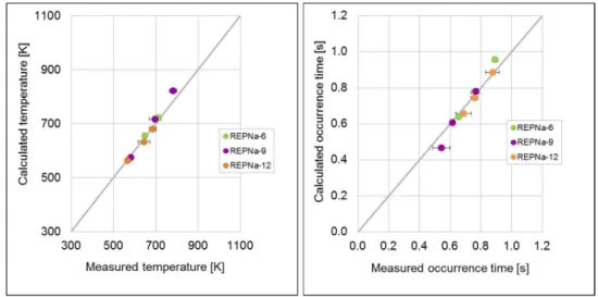
3.1. Sodium coolant temperatures
The instrumentation device of the CABRI tests included thermocouples (TC) placed at several axial and azimuthal locations; they were used to assess the radial and axial heat transfer in the fuel pellet - cladding - coolant system. As shown in Fig 1, the coolant maximum temperatures (at 3 axial levels) and their occurrence times during the pulse are very well reproduced by ALCYONE.
Fig 1. Calculated versus measured values of
left: maximum sodium temperature ; right: occurrence time of this maximum
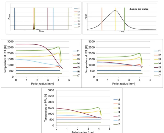
3.2. Temperature radial profiles in the fuel pellet
Fig 2 shows the fuel pellet temperature radial profile evolution during the three pulse tests considered. Radial profiles are plotted at the following times: (t1) before the beginning of the pulse; (t2) during the power rise; (t3) at peak power; (t4) during the power descent; (t5) at the end of the power descent; (t6) 10 s after TOP; (t7) 110 s after TOP (return to cold state).
During the short transient, the fuel temperature increases in a quasi-adiabatic way, resulting in an almost flat radial profile with a small peak localized in an outer ring close to the pellet periphery (this peak is not as marked and sharp as in UO2 calculations). Then, heat exchanges between the fuel rod and the coolant take place, leading to a parabolic temperature profile in the fuel pellet.
The higher the energy deposition, the higher the maximum temperature achieved in the pellet. While the temperature at fuel pellet centerline increases by about 1000 K in the REPNa-12 low-energy case, it increases by 2250 K in the REPNa-9 high-low-energy case, with a calculated maximum fuel temperature of 2790 K that remains consistent with the absence of fuel melting sign detected through posttest examinations.
Fig 2. (Peak Power axial Level PPL) Temperature radial profile evolution during pulse-irradiation above: illustration of the plotting times considered
top left: REPNa-9 case; top right: REPNa-6 case; bottom: REPNa-12 case
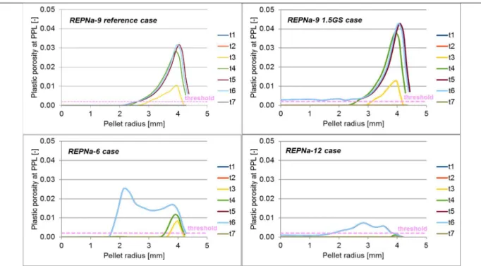
3.3. Grain boundary cracking and FGR
Fig 3 shows the radial profile evolution with time of the plastic porosity (threshold used to estimate the importance of grain boundary cracking). Grain boundary cracking is predicted in all considered cases, even in the REP-Na9 case with the lowest burnup. The modelling thus correctly reproduces the fact that grain boundary cracking does not solely depend on burnup to which the grain boundary gas content before the pulse is related. With respect to the simulation results of UO2 tests, grain boundary cracking is not restricted to the pellet periphery. The high plastic porosities globally match the experimental area where grain boundary cracking was detected in posttest examinations. It was detected globally on the whole radius, starting from the very external pellet rim (after about 100 µm) to an inward extension r/r0 of 82% (REPNa-6 case) and 75% (REPNa-9 and REPNa-12 cases) and appeared to be present although less important (actually none in REPNa-12 case) towards the internal part of the pellet.
Fig 3. Plastic porosity radial profile evolution during pulse-irradiation (N.B. Explanation about the “1.5GS case” appears in section 3.4)
Fig 4 shows the evolution of fission gas populations in the fuel pellets during the pulse transient:
• In the REPNa-9 low burnup case, FGR in the calculation with reference parameters occurs between r/r0 ~ 65% and the pellet rim. According to CARACAS, the UO2 matrix is the main contributor to the FGR (80%) except at the pellet rim where the matrix contribution and the subsequent Pu-clusters contribution (in the current homogeneous mechanical framework) are of the same order.
• In the average burnup REPNa-6 case, FGR occurs between r/r0 ~ 38% and the pellet rim. Contrary to the REPNa-9 case, the Pu-clusters are the main contributors to the FGR (70%) except on the pellet rim where the matrix contribution becomes higher.
• In the high burnup REPNa-12 case, FGR occurs between r/r0 ~ 33% and the pellet rim. The Pu-clusters are the main contributors to the FGR except on a large outer ring (from r/r0 ~ 90%) where the matrix contribution becomes predominant. The increasing importance of the matrix at the pellet rim is mostly due to the development of the HBS in this part of the pellet.
Fig 5 shows the time evolution of FGR and intergranular gas inventory during the pulse. The FGR kinetics is far from being smooth, which reflects the reaching of the grain boundary cracking threshold at different fuel pellet nodes. Note that MOX FGR starts before the pulse power peak and is not finished at the end of the pulse transient. REPNa-6 and REPNa-12 tests are rather slow pulses where FGR develops gradually by steps and is mainly composed of intergranular gas. Consequence of the high burnups of these fuel rodlets, the initial gas content at the grain boundaries is high (more than 30% of the total gas content). In the high-energy REPNa-9 case, the FGR is smoother and related not only to grain boundary cracking but also to an intragranular gas diffusion mechanism triggered by the high temperature at the pellet centerline (higher than 2700 K). This mechanism with a slow kinetics leads to additional FGR with respect to the initial intergranular gas inventory.
Fig 4. Gas concentration radial profile evolution during pulse-irradiation left: before pulse; right: after pulse
first line: REPNa-9 (reference) case; second line: REPNa-9 (1.5GS) case; third line : REPNa-6 case; fourth line: REPNa-12 case
Fig 5. Power, intergranular gas fraction and gas release fraction time evolution top left: REPNa-9 case; top right: REPNa-6 case; bottom: REPNa-12 reference case
(N.B. Explanation about the “1.5GS case” appears in section 3.4)
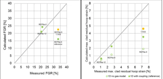
3.4. Discussion
FGR and clad deformation results are synthetized in Fig 6. As regards the maximum clad residual hoop strain, the reference length is the pre-test cladding diameter and not the as-manufactured one. With the present approach, the calculated values are in reasonable agreement with experimental results. Obviously, accounting for fission gas swelling improves the prediction of the maximum residual clad hoop strain (compare to the results with no fission gas model). The underestimation of the REPNa-9 maximum hoop strain is however noticeable. It may be due to a non-negligible contribution of Pu-clusters to fission gas swelling, contribution not considered in the present approach since the stress state is assumed uniform in the different phases.
Fig 6. Calculated versus measured values of the: left: FGR; right: maximum clad residual hoop strain (N.B. Explanation about the “1.5GS case” appears hereafter)
This relative importance of Pu-clusters versus the matrix is illustrated in Fig 7 where the radial profiles of fission gas swelling in the fuel are plotted assuming that it originates either only from the UO2 matrix (1) or from the UO2 matrix and the Pu-clusters in proportion to their volume fractions (2). This gives an idea of the underestimation of fission gas swelling in our reference calculations, based on configuration (1).
Fig 7. (Peak Power axial Level PPL) Before pulse gaseous swelling radial profile top left: REPNa-9 case; top right: REPNa-6 case; bottom: REPNa-12 case
Interestingly, due to its low burnup, only the REPNa-9 case has a fission gas swelling significantly increased by the introduction of the Pu-clusters contribution (by more or less 50%). In fact, the latter have a very high local burnup with a high gas content that prevail on the gas content of the matrix. This discrepancy between Pu-clusters and the matrix is reduced at high burnup which explains the smaller importance of Pu-clusters in the REPNa-6 and REPNa-12 cases. To account for this missing contribution in the fuel pellet expansion, an additional calculation of the REPNa-9 case has been undertaken, referenced “1.5 GS case” in all figures. The fission gas swelling strains have been multiplied by a factor 1.5. As can be seen, it leads to a much better estimation of grain boundary cracking (see Fig 3 where it now concerns the whole pellet radius, in agreement with posttest examinations), FGR and maximal cladding residual strain (see Fig 6).
Conclusions and prospects
The RIA 1.5D calculation scheme of ALCYONE V1.4, validated for UO2 fuels, has been extended to MOX fuels. The 3-phase description of MOX microstructure (UO2 matrix and two Pu-clusters phases) included in the fission gas model CARACAS for base irradiation and power ramp simulations has been used in RIA simulations. The extension to RIA required the implementation of a grain boundary cracking criterion, similar to the one developed from experimental compression tests for UO2, and a temperature criterion as regards FGR from any HBS zone. Despite this simple approach based on the current calibration of the fission gas model CARACAS for MOX fuels in base irradiation and power ramp results only and on a mechanical homogeneous framework, the differences between the CABRI pulses performed on
MOX fuels with various burnups and injected energies are satisfactorily reproduced (Na temperatures, FGRs and clad hoop strains). Only the application to high-energy tests on medium burnup fuel rods where the temperatures reached are far above those considered in the calibration of CARACAS led to some non-negligible underestimation of clad strains and FGR. As shown in the paper, the lack of any contribution from Pu-clusters to fuel pellet gas-induced swelling in the present approach might explain these results. To improve the results, the development of more advanced behaviour laws, where the stress states would be calculated per phase and not on average as it is the case today, is planned. An extension to MOX fuel RIA simulation of the 3-phase mechanical framework derived for steady states and power ramps may be contemplated [10]. In parallel, experimental data on MOX fuel as regards grain boundary cracking during RIA (phase-dependent) are necessary. Finally, helium release modelling during RIA may also be implemented [13].
It has been shown that the homogeneous modelling gives satisfactory results. An alternative and heterogeneous approach may be a complementary path towards a more local description of the MOX fuel behaviour under RIA conditions: if both heterogeneous and homogeneous approaches will give the same information and results at the macroscopic level, the heterogeneous one will enable to understand, via numerical simulations, what happens at lower (meso- and microscopic) scales.
REFERENCES
1. J. SERCOMBE et al., “1D and 3D modeling of PCMI during a RIA with ALCYONE V1.1”, Proc. of TopFuel Conference, Orlando, Florida, USA (2010).
2. B. MICHEL et al., “Modeling of pellet cladding interaction”, in: Compr. Nucl. Mater., pp. 677-712, R. KONINGS, Ed, Elsevier Ltd (2012).
3. J. SERCOMBE et al., “2D simulation of hydride blister cracking during a RIA transient with the fuel code ALCYONE”, EPJ Nuclear Sci. Technol., 2, 22 (2016).
4. I. GUÉNOT-DELAHAIE et al., “Simulation of RIA transients on UO2-M5® fuel rods with
ALCYONE V1.4 fuel performance code”, Nucl. Eng. Technol., 50, 268 (2018).
5. Y. UDAGAWA et al., “Experimental and analytical study on MOX fuel behavior under RIA-simulating conditions in the NSRR”, IAEA-TM on Fuel design and licensing of mixed cores for water cooled reactors, Vienna, 2011.
6. J. PAPIN et al., “Summary and interpretation of the CABRI REP-Na program”, Nucl. Technol., 157, 230 (2007).
7. F. LEMOINE, “Estimation of the grain boundary gas inventory in MIMAS/AUC MOX fuel and consistency with REP-Na test results”, J. Nucl. Sci. Technol., 43(9), 1105 (2006).
8. J. PAPIN et al., “Main outcomes from the CABRI test results”, NEA CSNI topical meeting on RIA fuel safety criteria, Aix-en-Provence, France (2002), OECD Nuclear Energy Agency, NEA/CSNI/R(2003)8, Vol.2, 61-81, (2003).
9. G. JOMARD et al., “CARACAS: An industrial model for description of fission gas behavior in LWR-UO2 fuel”, Proc. of Water Reactor Fuel Performance Meeting/TopFuel Conference,
Sendai, Japan (2014).
10. A. BOULORÉ et al., “Approach to better assess fission gas behaviors, applicable to fuels with complex microstructures”, Proc. of Water Reactor Fuel Performance Meeting/TopFuel Conference, Jeju Island, Korea (2017).
11. M. SALVO et al., “Experimental characterization and modeling of UO2 behavior at high temperatures and high strain rates”, J. Nucl. Mater., 456, 54 (2015).
12. M. SALVO et al., “Experimental characterization and modeling of UO2 grain boundary cracking at high temperatures and high strain rates”, J. Nucl. Mater., 460, 184 (2015).
13. V. MARELLE, “Validation of PLEIADES/ALCYONE 2.0 fuel performance code”, Proc. of Water Reactor Fuel Performance Meeting/TopFuel Conference, Jeju Island, Korea (2017).