HAL Id: cea-02421905
https://hal-cea.archives-ouvertes.fr/cea-02421905
Submitted on 20 Dec 2019
HAL is a multi-disciplinary open access
archive for the deposit and dissemination of
sci-entific research documents, whether they are
pub-lished or not. The documents may come from
teaching and research institutions in France or
abroad, or from public or private research centers.
L’archive ouverte pluridisciplinaire HAL, est
destinée au dépôt et à la diffusion de documents
scientifiques de niveau recherche, publiés ou non,
émanant des établissements d’enseignement et de
recherche français ou étrangers, des laboratoires
publics ou privés.
Thermo- and photo- oxidation reaction scheme in a
treatment system using submerged plasma
D. Milelli, F. Lemont, L. Ruffel, T. Barral, M. Marchand
To cite this version:
D. Milelli, F. Lemont, L. Ruffel, T. Barral, M. Marchand. Thermo- and photo- oxidation reaction
scheme in a treatment system using submerged plasma. Chemical Engineering Journal, Elsevier, 2017,
317, pp.1083-1091. �10.1016/j.cej.2017.02.069�. �cea-02421905�
Thermo- and photo- oxidation reaction scheme in a treatment system using submerged
plasma
D. Milelli, F.Lemont*, L. Ruffel, T. Barral, M. Marchand
CEA, DEN, DTCD, SCDV, LPIC, F-30207 Bagnols-sur-Cèze, France
*Corresponding author: [email protected]
Abstract: Some of hazardous liquid organic wastes, radioactive or not, are waiting from outlet to be destroyed. The ELIPSE
process is a new technology of organic liquid destruction, involving a thermal plasma working under a water column, which ensures the cooling, the filtration and the scrubbing of the gases coming from the degradation. This study deals with the ability of the ELIPSE process to destroy the pure organic liquids and then to reduce the amount of organic matter remaining in the aqueous solution by means of the thermal or radiative properties of plasma.
Preliminary test have shown how efficient the process is for the destruction of the organic liquids when they are directly fed in the plasma hearth. Extensive researches have been performed to assess the ability of the submerged plasma to destroy the remaining organic matters either by reinjecting them with the aqueous solution into the plasma or by using the UV ray coming from the plasma itself. A comparison of the experimental results obtained with various mechanisms proposed by the work carried out highlighted that this UV radiation could, by excitation of water molecules, produce radicals OH° which may either dimerise to produce hydrogen peroxide H2O2, or react with organic substances present. The calculation of an activation energy of 8.5 ± 0.9kJ.mol-1 during the experiments shows that these radicals OH° act directly after having been formed which explains a low H2O2 content stability when the solution contains organic compounds. Thus, this photo-oxidation taking place in the water column could be used to improve the destruction of residual organic matter in the solution by maintaining the plasma after processing a given amount of organic liquids.
Keywords: Organic liquids destruction – Submerged plasma – Plasma UV emission – Reactive species production –
Photochemistry – Reaction scheme
1. Introduction
Processing industrial organic liquid waste, whether radioactive or not, represents a major challenge because this waste comes in many different forms and is widely dispersed in the various facilities in which it is produced. Treatment currently available is often exclusive, as is the case for trichlorethylene, polychlorobiphenyle (PCB) or chlorofluorocarbon (CFC) with chlorine content greater than 7% mass. The latter are currently treated in a conventional burner at the base of an oven that
has to treat for at least 2s at more than 1,200°C [1, 2] which requires large-sized structures with metal or refractory components subjected to extremely corrosive physical-chemical conditions.
A desirable technique would be one that allows universal treatment of these various liquids, regardless of their compositions, in the same unit.
The first studies conducted in this area were mainly focused on evaluating the capability of a submerged plasma to produce HO. or O. radicals, or even ozone, in a solution. The idea was then to determine the means for decontaminating aqueous solutions contaminated by organic pollutants. In the 1980s, Alekseev et Al. 3-4 studied heat transfer from a plasma to the aqueous solution in which it is submerged, and estimated that the quenching rate for gases is approximately 107K.s-1. Extremely high speeds such as these made it possible to fix the radicals capable of oxidizing the organic compounds present in the water.
It was based on this phenomenon that certain processes were proposed as possible decontamination solutions. Bernier et al. 5, for example, propose a concept using an arc plasma torch submerged in a solution containing cyanides to be decontaminated. This concept uses a draft tube working as an hot air lift near the plasma plume.
Although this concept can be used to treat aqueous solutions, it cannot be used for the treatment of pure organic liquids. Other processes have therefore been developed to propose suitable outlets. Uchiyama et al. 6, for example, propose a system which is quite representative of what has been proposed by others. It uses a technology which destroys organic liquids in a combustion chamber, where the output is atomized directly in an aqueous solution. A system was designed to treat flow rates of approximately 1L.h-1 for waste solvents (TBP-Dodecane) used in fuel treatment operations.
Studies of this type of process show that the combustion is not truly submerged, as a combustion chamber with refractors is used. The heated zone which generates the combustion reactions and gas transit is therefore quite large, and subject to the aggressive nature of the combustion gases which contain heteroatoms that may cause corrosion. The range of liquids that could be treated in this type of structure is therefore quite small.
Processes have also been developed by JAEA in Japan 7 for the treatment of TBP/dodecan. JAEA has two main processes for this application, a steam reforming process and a submerged combustion process. In the second case, the liquid mixture is supplied at a rate of 1-3 kg.h-1 to a gasification chamber where it is vaporized and pyrolyzed. The decomposition gases are then completely burned in a submerged combustion reactor to prevent soot and dioxins generation.
In this latest example, what is called “submerged combustion” concerns only the afterburner and not the whole thermal treatment of the waste. Corrosion may then dramatically occur in the hot zone.
Studies conducted on the subject at the CEA have enabled a new procedure to be proposed whose concept is based on the implementation of a submerged arc plasma in which the liquid to be treated is directly injected. Called ELIPSE [8], it means
the treatment of various organic liquids can be considered by implementing chemical reactions of type (1) carried out at extreme speeds at the core of the plasma.
CxHyXM
𝑝𝑙𝑎𝑠𝑚𝑎/𝑂2
→ x CO2 + 𝑦
2 H2O + XH + MOz (1)
X and M represent the hetero atom generally produced in the form of a mineral acid that subsequently has to be neutralized and M a mineral charge initially present and oxidized in the oxygen plasma.
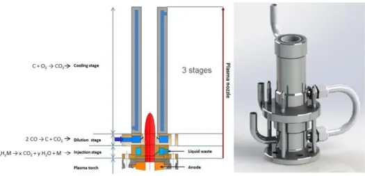
The current configuration of the ELIPSE process is described in Figure 1. The plasma torch can be seen submerged at the bottom of a vessel filled with water which is continuously processed in a system with a heat exchanger, a filter and a neutralization system in series. The plasma torch with a power that can reach 50kW has a nozzle specially designed to receive and destroy an organic load supplied at its base. It is the only hot point in the process, as the rest is kept at the temperature of the aqueous solution which ensures quenching, filtering and washing of the gases from the reaction (1). This set of functions essential in a single step explains the high degree of compactness of the process. Keeping the assembly cold explains the optimal resistance to any form of corrosion which leads to considering a system of 'universal' treatment of organic liquids.
Fig. 1. The ELIPSE process Diagram
2. Material and methods
2.1 Fitted out plasma nozzle
The combustion reaction of the organic load as described by equation (1) can only be optimal on the condition that a suitable nozzle is set up in which the organic liquid brought to high temperature reacts with the oxygen plasma by
generating combustion products containing little or no undesirable compounds such as carbon monoxide (CO) or certain derived carbonyls. Contrary to the tube drafting aqueous solution in the process proposed by Bernier [5], the plasma nozzle is design as a micro-reactor able to be fed with pure organics together with pure oxygen.
This nozzle is placed downstream of the torch anode producing a stream of gas of about 230NL.min-1. In addition, the nozzle is composed of three stages as represented in Figure 2:
- An injection stage that introduces the liquid directly into the plasma
- A dilution stage which ensures re-injection of the solution in which the plasma is immersed. This stage has a dual functionality:
To reintroduce the solution containing organic residue from incomplete destruction efficiency of around 99.7%. This re-injection will help study the ability of the system to improve overall destruction efficiency.
To cool by spraying water in order to induce the production of CO2 by displacing the CO/CO2 balance.
- A cooling stage which gives a sufficient stay time to establish chemical reactions including the combustion of any carbonaceous particles present.
Fig. 2. Diagram and mechanical design of the plasma torch nozzle in the reactor.
The average volume of the nozzle shown in Figure 2 is about 60cm3. The average temperature of the gas inside is 2,700K which leads to average flow speeds of about 400m.s-1. In these conditions, fitting out the cooling stage as shown in Figure 2 ensures a stay time of about 0.2ms.
We use a Black-Comet brand, BLK-C spectrometer capable of detecting a range of wavelength between 190 and 850 nm (UV-visible field). This device measures the intensity of light or ultraviolet radiation using fibre optics and an integrator, and restores it in the form of acquisition via the SpectraWiz Shortcut software.
Measurements of radiation in actual submerged plasma conditions and with bubbles in the reactor, are carried out by varying the radius and height as per the device shown in Figure 3. A programme using Matlab software, implemented based on the interpolation of values between the measured points, enables us to obtain ultraviolet radiation intensity and temperature mapping in the entire field, for uses of the process with and without the nozzle above the plasma torch. The Lagrangian interpolation function used helps reach well-spaced measuring points when calculating intermediate points according to the splines method. The calculation performed is relatively refined; the equality of derivatives to the right and left of the measuring points softens the path of the curves. The error of the spline function is proportional to the fourth power interpolation intervals [9].
We assume that the reactor is perfectly symmetrical and we interpolate our results with a step of 0.1 for the height and radius.
Fig. 3. Scheme of the UV measurement.
2.3 The various analytical methods used
At the top of the reactor, a gas sample is taken systematically and analyzed in real time by a gas analyzer ROSEMOUNT EMERSON type XSTREAM with IR absorption. Measurements are made on CO2 band at 2349 cm-1 and CO band at 2170 cm-1. The results are rendered in volume percent.
The thermo-oxidation efficiency is evaluated by analyzing the Total Organic Carbon destruction rate 𝜂(𝑡) in the residual solution (Eq. 2). The TOC is measured with a SHIMADZU analyzer TOC-L Series, using the 680°C combustion catalytic
method. A typical analysis for TOC measures both the total carbon (TC) and the inorganic carbon (IC), the latter representing the content of dissolved carbon dioxide and carbonic acid salts. Subtracting the inorganic carbon from the total carbon yields TOC. The measurement relative uncertainty is estimated to be around 2%.
Experiments with and without plasma nozzle have been conducted to evaluate the hydrogen peroxide production rate in ELIPSE aqueous medium. The H2O2 concentration can be determined by a colorimetric analysis with 10-2 mol.L-1 of potassium permanganate on solution samples taken throughout the tests. The colorimetric reaction equation is:
2 MnO4-(aq) + 6 H+(aq) + 5 H2O2(aq) → 2 Mn2+(aq) + 8 H2O(l) + 5 O2(g)
3. Results and discussion
3.1 Performance of the system to destroy pure organic liquids
The nozzle qualification described in the previous paragraph was carried out by means of a series of processing tests of the tributylphosphate (TBP, Sigma Aldrich Company) and dodecane (Sigma Aldrich Company) mixture. This mixture is a preferential extractant in the PUREX process which ensures the spent fuel is reprocessed.
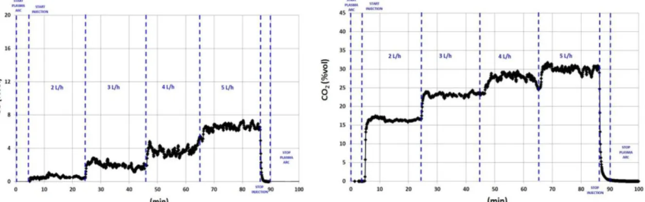
The experiment on the ELIPSE process consisted of injecting a flow rate ranging from 2 to 5L.h-1 for 90 minutes at the base of the nozzle described in Figure 2. The plasma operates at a constant power of about 50kW. The oxygen and argon (internal cathode protection gas) flow rates are also constant for values of 200NL.min-1 and 30NL.min-1 respectively) Figure 4 presents the results of the analysis of the CO/CO2 pair by means of the analyser located downstream of the condenser. The CO and CO2 levels clearly vary from 0.5 to 6.8% and 16 to 30% concentration respectively depending on the different flow rates introduced.
Fig. 4. Change in CO and CO2 content during the destruction test of a TBP/dodecane mixture.
The results given in Figure 4 show a normal change in the composition of the gas for processing conditions that remain constant because the power as well as plasma gas flow remain unchanged throughout the test.
Over and above this normal change, these results when compared to the theoretical composition of the reaction mixture brought to the mean temperature of 2,700K in the nozzle as a whole, tell us that the thermo-chemical balances are generally achieved. Actually, the modelling of the chemical system matching the processing of the various experimental flows, as revealed in Figure 5, shows very good consistency between the levels of CO emitted according to theoretical and experimental data represented. A more significant difference for CO2 is to be recorded, but which remains permissible. The modelling of chemical balances was carried out using Factsage 6.4 software on a baseline for processing of 1L.h-1 of extractant representing 0.9 mole of TBP, 3.3 moles of dodecane which are mixed with 536 moles of oxygen and 80.3 moles of argon.
Fig. 4. Comparison of experimental and theoretical concentration fractions of CO and CO2 emitted during the processing of various flow rates of the TBP/Dodecane mixture.
Achieving a balance is important because it demonstrates that the nozzle is large enough with respect to the system's stay time at the mean temperature of 2,700K.
The measurement of TOC in the water in which the plasma torch bathes helps compare the amount of residual organic carbon in the water to the amount of carbon having been introduced into the plasma torch. It enables the destruction efficiency of the process to be calculated according to the following equation (2):
𝜂(𝑡) = 𝑄𝑐𝑖(𝑡𝑄)−𝑄𝐶𝑠(𝑡)
𝑐𝑖(𝑡) (2)
QCi (t) is the total amount of organic carbon introduced into the plasma at time t and QCs (t) is the total amount of organic carbon measured in the solution at time t.
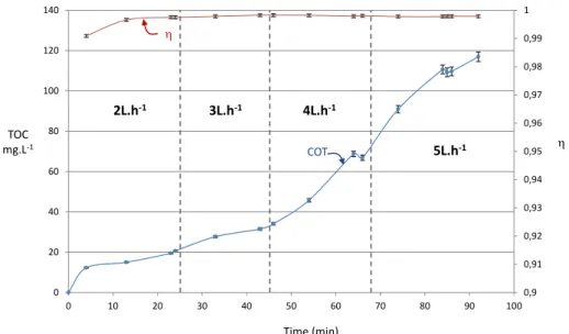
Figure 5 shows both the change in TOC over time and the change in destruction performance calculated according to the equation (2). These results show that the TOC regularly increases over time which means that the aqueous solution
0 5 10 15 20 25 30 0 1 2 3 4 5 % V ol Flowrate (L.h-1) CO2exp CO2th CO th CO exp
accumulates residual organic matter but without the efficiency degrading over time. It remains between values ranging from 99.7 to 99.9% with a low value of 99.1% recorded for the first sampling.
The system operates in a semi-closed circuit in that the organic liquid to be processed is introduced continuously into the plasma nozzle while the amount of solution remains constant in the reactor, the organic compounds going into solution accumulate over time at a rate dependent on the injection flow as illustrated in Figure 5. It is therefore important to assess the capabilities of the system to minimise this build-up while seeking to improve the destruction efficiency of the organic liquids introduced.
This research is the subject of the rest of the study which will look at the overall ability of the process to reduce the amount of organic matter in the aqueous solution by means of the various thermal or radiative properties of the plasma.
Fig. 5. Change in the TOC and performance of processing over time for different feeding rates
3.2 Ability of the system to destroy residual organic matter in the aqueous solution
The study described here was conducted using an aqueous solution containing ethanol to simulate organic matter likely to go into the solution during processing. This simulator was chosen because, on the one hand it represents an organic compound of low molecular mass and, on the other hand it is partially oxidised.
Figure 5 helps analyse the content of residual organic matter in the process solution at about 1,200ppm after 24 hours of continuous processing. This indicative content will be the basis for the work described below.
The capacity to oxidise the residual organic matter was assessed by analysing the process’s intrinsic two channels as represented in Figure 6: 0,9 0,91 0,92 0,93 0,94 0,95 0,96 0,97 0,98 0,99 1 0 20 40 60 80 100 120 140 0 10 20 30 40 50 60 70 80 90 100 Time (min) TOC mg.L-1 COT h h 2L.h-1 3L.h-1 4L.h-1 5L.h-1
- Thermo-oxidation of the compounds by re-injection of the solution into the oxygen plasma nozzle - Photo-oxidation of the compounds under the effect of radiation from the upper part of the nozzle
Fig. 6. Potential channels of destruction of the residual organic compounds in solution
To find out the relative weight of one or the other channel, two experiments were conducted using 60 litres of water in which 200mL of ethanol were added. The first experiment involved operating the plasma torch without injecting the solution into its nozzle. In this case, the change in TOC is only linked to the chemical degradation taking place in the core of the aqueous solution, above the plasma torch. The second experiment involved operating the plasma torch with a recirculation of 0.3L.min-1 of the solution in the nozzle. In this case, the change in the TOC is related to the organic degradation taking place both inside and outside the nozzle. In both cases the change in TOC is shown in Figure 7. In both cases, the pH varies from 7 to 4.5.
Fig. 7. Change in TOC measured during the processing of the aqueous solution contaminated by ethanol without re-injection of the solution
(Photo oxidation) and with re-injection of the solution in the plasma nozzle (Thermo-oxidation + Photo-oxidation)
Solution Injection (CH3CH2OH)aq Thermo-oxydation Zone CH3CH2OH + O2= CO2+ H2O hn Photo-oxydation zone H2O H2O2 OH° UV CH3CH2OH CO2+ H2O 0 200 400 600 800 1000 1200 1400 0 50 100 150 Thermo oxydation + Photo oxydation Photo oxydation Time (min) TOC mg.L-1
Figure 7 shows that the TOC change curves are very close with the maximum deviation measured being 79 ± 2ppm for an average of 36 ± 1 ppm. The IC measurement gives an average value of 1.4ppm what can be attributed to the formation of hydrogen carbonate.
The share of thermo-oxidation of the solution therefore appears minor in the destruction process of residual organic matter in solution. This observation, to date unexplained, could be mean that the speed of transition of the gases (about 400m.s-1), which leaves no time for the solution to vaporize in the nozzle and to make the organic compounds reactive in relation to the plasma environment. Experimental studies and modelling currently underway will soon bring answers to this observation.
The above results demonstrate the ability of plasma radiation to cause a reaction that degrades the organic matter in the aqueous solution above the plasma. In line with the results obtained at the core of the nozzle, the thermal part of this degradation is also negligible which means that the photochemical part is predominant since in both cases, the degradation rate achieved after 3 hours of processing is about 89%. The study therefore naturally focused on plasma's radiative role in the intrinsic purification of the solution.
3.3 Submerged plasma photochemical activity
3.3.1 Characterization of plasma radiation
The radiation emitted by the plasma torch was measured according to the system described in the first part. The measurements were taken with and without a plasma nozzle in a reactor that is not filled with water. Findings show that an argon plasma emits very little in the ultraviolet range since spikes appear from 650 nm which is consistent with studies conductedon an argon plasma in 2003 by Guchardi R. and Hauser P.C. and in 2015 by Jablonowski H. et al. [10, 11]. On the other hand, in the presence of an Ar-O2 plasmagene mixture (20%/80%) peaks appear in the ultraviolet spectrum. It has been noticed that the presence of the nozzle changes the spectrum obtained as shown in Figure 8. Without a plasma nozzle, only one double peak appears at a wavelength of 325nm. Implementing the nozzle causes a second peak to appear at lower wavelengths centred around 308nm. This radiation can be at the origin of photochemical reactions as highlighted by the results described in Figure 7.
Fig. 8. Comparison of UV-visible radiation from Argon and Argon-Dioxygen plasmas.
Plasma radiation mapping was conducted with and without a plasma nozzle in the reactor filled with water from the measuring device described in paragraph 2.2. This mapping represented in Figure 9 shows that when the measurement is made without a nozzle, the radiation is more diffuse and has an intensity about 70% lower than when the measurement is performed with the nozzle. The radiation obtained with the nozzle has to be sufficient to generate reactive species as was demonstrated by spectrum analyses performed on submerged plasmas [12, 13]. These studies have shown the capacity of these plasmas to produce OH° radicals and molecular oxygen.
Fig. 9. Modelling of the UV intensity in ELIPSE with a plasma nozzle (A) and without a plasma nozzle (B).
3.3.2 Production of reactive species
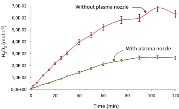
The reactive species generally produced in photochemical processes are hydrogen peroxide and OH° radicals coming from its dissociation in an aqueous environment. The hydrogen peroxide H2O2 content was thus measured in two previously studied configurations, with and without a nozzle.
It is clear that plasma formed in the process induces a reaction between the water and dioxygen introduced, which generates hydrogen peroxide (Fig. 10). The amount of H2O2 obtained in the absence of the plasma nozzle is about 6.5 10-2 mol L-1, whereas with the nozzle 2.7 10-2 mol L-1 were recorded at the end of the test. This difference can be explained by limitation of the UV irradiation zone, as represented in Figure 9. Thus, it could be interesting to optimize the geometry of the nozzle in order to increase the hydrogen peroxide production during operation of the process.
Fig. 10. Change in hydrogen peroxide over time within ELIPSE.
The work carried out on the production of hydroxyl [14] radicals by UV photolysis has highlighted the effectiveness of irradiation with a wavelength centred on 306nm which is compatible with the wavelength emitted in the aqueous solution when the plasma is equipped with its nozzle as shown on the spectrum of Figure 8. It proposes a production system of radicals OH° from water molecules excited by the UV radiation according to the following simplified reaction sequence:
hn+ H2O H2O* (3) hn + H2O* OH° + H° or O + 2H (4) OH° + OH° H2O2 or H2O + O (5) 0,0E+00 1,0E-02 2,0E-02 3,0E-02 4,0E-02 5,0E-02 6,0E-02 7,0E-02 0 20 40 60 80 100 120 Time (min) H2 O2 (mol.L -1)
With plasma nozzle Without plasma nozzle
According to this system, it appears that radicals OH° are produced at the nozzle outlet before recombining to produce hydrogen peroxide in measurable quantities at the core of the process. This hydrogen peroxide can in turn be degraded by photolysis or secondary reaction [15] with the hydroxyl radicals according to equations of the following type:
H2O2 + hn 2OH° (6)
OH° + H2O2 H2O + HO2° (7)
HO2° + H2O2 O2 + H2O + OH- (8)
The kinetics of hydrogen peroxide production can then be regarded as the result of a formation reaction of order zero overall with a constant kH2O2 and a destruction reaction of order one overall with a constant b [15]. The production law may then be considered as follows:
𝑑(𝐻2𝑂2)
𝑑𝑡 = 𝑘𝐻2𝑂2− 𝑏(𝐻2𝑂2) (9)
The comparison of the solution to this equation with the experimental results helps calculate an overall first order destruction constant of 3.5x10⁻⁴s-1 which is clearly in line with the work done by P. Lukes and Col. [15] which offers a value of 2.05x10⁻⁴s-1 for measures carried out in a system implementing pulsated radiative corona discharges in a submerged environment. It is worth noting that the presence of the plasma nozzle that significantly changes the UV radiation as shown in Figure 9 does not influence the disappearance kinetics which indicates that in our application, equation (6) has a negligible effect on the mechanism. The interaction between the radicals formed and the hydrogen peroxide is the main cause of destruction of the latter compound.
The implementation of the nozzle on the other hand has an effect on the constant kH2O2 since it attains 9.8x10⁻⁶ mol.s-1 for an experiment without a plasma nozzle and 2.8x10⁻⁵ mol.s-1 for a reaction with a nozzle. This variation is related to a change in the experimental conditions expressed here by a drop in the flow of UV photons due to the plasma nozzle being set up.
3.3.3 Activity of reactive species
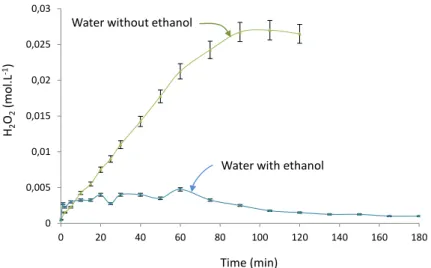
The introduction of ethanol in amounts similar to those used previously helped to assess the activity of reactive species created by the plasma radiation. This assessment was conducted by the H2O2 follow-up over time. Figure 11 shows, on the same graph the change in hydrogen peroxide content measured previously in the presence of the plasma nozzle and this same change when 200mL of ethanol has been added to the water.
It appears that the H2O2 content remains at a concentration of less than 5 x 10⁻³ mol. L-1 i.e. less than 5 times the value reached by the platform when ethanol is not present. With reference to the hydrogen peroxide production mechanism, this
is linked to disruption of the reaction (5) by the consumption of radicals OH° which occurs with speed constants of around 10-7 cm-3 s-1 so that the dimerization of the hydrolyle radicals according to the reaction (5) occurs with speed constants of around 10-9 cm-3 s-1 [16].
Fig. 12. Change in hydrogen peroxide content in an aqueous solution containing and not containing ethanol during irradiation by
submerged plasma.
The overall chemical reaction between the ethanol and the radicals can be expressed according to the following equation (10):
C2H5OH + 6OH° 2CO2 + 3H2O + 3H2 (10)
The consumption of radicals OH° is represented by a hydrogen peroxide content that remains constant. The integration of equation (5) in equation (10) helps consider the following overall review:
C2H5OH + 3H2O2 2CO2 + 3H2O + 3H2 (11)
By considering constant H2O2 content, the kinetics of the disappearance of ethanol simulating an organic residual in solution can then be written as follows:
𝑑(𝐶2𝐻5𝑂𝐻)
𝑑𝑡 = 𝐾(𝐶2𝐻5𝑂𝐻) (12)
with K = k (H2O2)c3 where k is the kinetic constant of the reaction (12), and (H2O2)c3 the constant value of concentration in hydrogen peroxide measured during the experiment. (H2O2)c3. Thus K is the apparent kinetic constant of the reaction (11)
0 0,005 0,01 0,015 0,02 0,025 0,03 0 20 40 60 80 100 120 140 160 180 Time (min) H2 O2 (mol.L -1)
Water with ethanol Water without ethanol
which is order 1. The integration of this expression allows to link the change in ethanol concentration over time as per the equation (13):
Ln(C2H5OH) = Ln(C2H5OH)0 + Kt (13)
Three experiments carried out under the same conditions but at three different solution temperatures (42°C, 50°C and 60°C) helped measure changes in the TOC similar to those represented in Figure 7. The results obtained at these 3 temperatures helped to draw the curves Ln(C2H5OH) = f (t) represented in Figure 13 and to deduce the three apparent kinetic constants. K(42°C) = 2.21x10⁻⁴s-1, K(50°C) = 2.36x10⁻⁴s-1, K(60°C) = 2.63x10⁻⁴s-1.
Fig. 13. LinesLn(C2H5OH) = f(t) during the processing of solutions containing approximately 1,200ppm of ethanol at 3 different temperatures
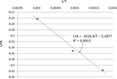
The K values according to a Arrhenius law type= 𝐾0𝑒−
𝐸𝐴
𝑅𝑇
,
the line LnK = f (1/T) helps to determine the activation energy ofthe oxidation of ethanol diluted in water by radicals OH°. The resulting path represented in Figure 14 helps calculate a value for the activation energy of 8.5 ± 0.9kJ.mol-1 which is in total agreement with values of around 10 ± 5kJ.mol - 1 available in documentation [17]. This agreement demonstrates that these radicals OH° produced by UV radiation coming from plasma are at the origin of the degradation of ethanol in the experiments presented here and which will therefore be responsible for the degradation of the residual organic matter remaining in solution after the processing of the organic liquids injected into the plasma Ar/O2.
It is assumed that in the range of monitored pH (from 7 to 4) the proposed mechanism is not affected. However, further studies are underway to assess the influence of the pH on the results in a broader range. This should enable to propose an operating point when the elimination of residual organics would be required after treatment.
-7 -6,5 -6 -5,5 -5 -4,5 -4 -3,5 -3 0 20 40 60 80 100 120 140 160 180 200 Temps (min) Ln (C2 H5 OH) T = 42°C / Ln(C2H5OH) = -0,0133t -3,6848 / R2= 0,9939 T = 50°C / Ln(C2H5OH) = -0,0143t -3,6788 / R2= 0,9954 T = 60°C / Ln(C2H5OH) = -0,0158t -3,7038 / R2= 0,9927
Fig. 14. LinesLnK = f(1/T) for the reactions described above.
3.4 Chemical review and conclusion
The processing of pure organic liquids injected into a submerged oxygen plasma reaches an average destruction rate of 99.8% according to the experiences described in paragraph 3.1. This destruction is directly related to a combustion process under special conditions in which temperatures are around 2,700 K and in which gas speeds are supersonic, i.e. around 400m.s-1. This environment requires extremely short stay times of around one millisecond which could possibly be increased by optimizing the gas flow in the nozzle. A modelling approach associated with current experimental measurements must help assess such a possibility by a readjustment of the internal design of the nozzle.
If internal combustion stage achieves this average destruction rate of 99.8%, the studies presented herein have highlighted that the properties of the plasma could be used to refine destruction efficiency by processing the residual organic matter introduced into the solution and whose content after 24 hours of process operation as described can be estimated at about 1,200ppm.
It has been shown that submerged plasma could actually be the cause of destruction of the residual organic matter in solution. It has been shown that the thermal properties of this very plasma cannot be the cause, mainly for reasons of mean stay time in the nozzle, which does not leave the time required for vaporization of the solution. However, it has been shown that the UV radiation from the plasma was at the origin of this process by phenomena which lead to the formation of hydrogen peroxide in the core of the aqueous solution. A comparison of the experimental results obtained with various mechanisms proposed by the work carried out also highlighted that this UV radiation could, by excitation of water molecules, produce radicals OH° which may either dimerise to produce hydrogen peroxide H2O2, or react with organic substances present. The calculation of an activation energy of 8.5 ± 0.9kJ.mol-1 during the experiments shows that these radicals OH° act directly after having been formed which explains a low H2O2 content stability when the solution contains organic compounds. These results help to refine the overall operating system according to a process described in Figure 14.
-8,44 -8,42 -8,4 -8,38 -8,36 -8,34 -8,32 -8,3 -8,28 -8,26 -8,24 -8,22 0,00295 0,003 0,00305 0,0031 0,00315 0,0032 Ln K 1/T LnK = -1019,4/T – 5,1877 R2= 0,9915
Fig. 14. Overall operating system of submerged plasma.
In this diagram, there is a geographical isolation of the thermo-oxidation and photo-oxidation. The former at the pure organic liquid injection area in the first part of the plasma torch nozzle and the latter taking place in the water column, just at the nozzle outlet. An intermediate zone called shift zone is what allows reactions to be balanced by arranged cooling of the gas in an area where their speed is very high. The future of the mineral loads present in the liquid to be processed depends on the chemical properties of the aqueous solution since they may precipitate in the form of oxide or a mixed MOX type compound or possibly MX beyond the solubility of the latter. Precipitated matter may thus be continuously eliminated by appropriate filtration.
The results obtained show that the photo-oxidation could be used to improve the destruction of residual organic matter introduced into the solution by maintaining the plasma after processing a given amount of organic liquids. This maintenance of plasma will enable the solution to be processed according to TOC reduction profiles similar to those described in Figure 7. It is important to note that the addition of a Fe2+ type catalyst to activate Photo-fenton type reactions will have no effect given the instantaneous consumption of radicals OH° which cannot dimerise to form hydrogen peroxide. This point which has been validated experimentally strengthens the validation of the overall system described in Figure 14.
References:
[1] ARKEMA. PCB et ARKEMA à Saint-Auban. (2008) Available from: http://www.paca.developpement-durable.gouv.fr. [2] TREDI. Implantation Saint Vulbas de TREDI/groupe Séché. (2012) Available from:
http://www.groupe-seche.com/implantation_40_25.html. CxHyXMOz O2
Plasma torch
HX H3O+/ X -UV H2O OH° CaHbOc CO2+ H2O + e CaHbOc CO2 CO2 HCO3 -CO32 -pH e CaHbOc H2O + HX + MOa (1+e) CaHbOc CO2 CO+CaHbOc H2O H2O2 MOXb Zone 1 Zo n e 2 Zone 3Thermo - oxydation Shift
Photo – oxydation
Water column
MOa
MOa
3 Alekseev NV., Pozdnyakov OE., Shorin SN., Study of the interaction between a hot gas jet and a liquid bath. J Eng Phys Thermophys 44(4). pp 358-363, 1983
4 Alekseev NV.,Samokhin AV., Belivtsev AN., Zhavoronkova VI., Thermal-plasma jet oxidation of phenol in aqueous solutions. High Energy Chem 34(6). pp 389-393, 2000
5 Bernier JL., Fortin L., Kimmerle FM., Boulos MI. Kasireddy V., Soucy G.. Thermal plasma reactor and wastewater treatment method. Patent – WO97/22556 – 1997.
6 Uchiyama G., Maeda M., Fujine S., Amakawa M., Uchida K., Chida M. Development of spent solvent treatment process by a submerged combustion technique. Journal of Nuclear Science and Technology. 31(3) pp.228-239. 1994
7 Nakagama A., Sone T., Sasaki T, Nakazawa O., Tashiro K., Performance of Steam Reforming Technology in a Long Term Treatment of Waste TBP/Dodecane. WM2011 Conference, February 27 – March 3, 2011, Phoenix, AZ
[8] Mabrouk M., Lemont F., Baronnet J.M., “Incineration of radioactive organic liquid wastes by underwater thermal plasma”, Journal of Physics: Conference Series, 12th High-Tech Plasma Processes Conference (HTPP-12), (2012) 406. http://iopscience.iop.org/1742-6596/406/1/012002)
[9] Ron A., “Review of Interpolation using Cubic Splines”, CS412: Introduction to numerical analysis, 2010.
[10] Guchardi R. and Hauser P.C., “A capacitively coupled microplasma in a fused silica capillary”
,
J. Anal. At. Spectrom.,(2003) 18, 1056–1059.
[11] Jablonowski H., Bussiahn R., Hammer M.U., Weltmann K.D., Von Woedtke T. and S. Reuter, “Impact of plasma jet vacuum ultraviolet radiation on reactive oxygen species generation in bio-relevant liquids”, Physics of Plasmas, (2015) 22. 122008-1/122008-10
[12] Kim P.Y., Kim Y.S., Koo I.G., Jung J.C., Kim G.J., Choi M.Y., YO Z., Collins G.J., “Bacterial inactivation of wound infection in a human skin model by liquid-phase discharge plasma”, Public Library of Science ONE, (2011) 6. http://dx.doi.org/10.1371/journal.pone.0024104
[13] Stalder K.R., McMillen D.F. and Woloszko J., “Electrosurgical plasmas”, J. Phys. D : Appl. Phys., (2005) 38, 1728-1738. [14] Attri P., Kim Y.H., Park D.H., PARK J.H., Hong Y.J., Uhm H.S., Kim K., Fridman A and Choi E.H., “Generation mechanism of hydroxyl radical species and its lifetime prediction during the plasma-initiated ultraviolet (UV) photolysis”, Scientific
Reports, (2015) 5. http://www.nature.com/articles/srep09332
[15] Lukes P., Clupek M., Babicky V. and Sunka P., “Ultraviolet radiation from the pulsed corona discharge in water”, Plasma
[16] Nemcova L., Nikiforov A., Leys C. and Krcma F., “Chemical efficiency of H2O2 production and decomposition of organic compounds under action of DC underwater discharge in gas bubbles”, IEEE Transactions on Plasma Science, (2011) 39, 865-870.
[17] Morozov I., Gligorovski S., Barzaghi P., Hoffmann D., Lazarou Y.G., Vasiliev E., Herrmann H., “Hydroxyl radical reactions with halogenated ethanols in aqueous solutions : kinetics and thermochemistry”, International Journal of Chemical Kinetics, (2008) 175-188.