HAL Id: hal-01382444
https://hal.sorbonne-universite.fr/hal-01382444
Submitted on 17 Oct 2016
HAL is a multi-disciplinary open access
archive for the deposit and dissemination of
sci-entific research documents, whether they are
pub-lished or not. The documents may come from
teaching and research institutions in France or
abroad, or from public or private research centers.
L’archive ouverte pluridisciplinaire HAL, est
destinée au dépôt et à la diffusion de documents
scientifiques de niveau recherche, publiés ou non,
émanant des établissements d’enseignement et de
recherche français ou étrangers, des laboratoires
publics ou privés.
Executing Secured Virtual Machines within a Manycore
Architecture
Clément Dévigne, Jean-Baptiste Bréjon, Quentin L. Meunier, Franck Wajsbürt
To cite this version:
Clément Dévigne, Jean-Baptiste Bréjon, Quentin L. Meunier, Franck Wajsbürt. Executing Secured
Virtual Machines within a Manycore Architecture. Microprocessors and Microsystems: Embedded
Hardware Design (MICPRO), Elsevier, 2016, �10.1016/j.micpro.2016.09.008�. �hal-01382444�
Executing Secured Virtual Machines within a
Manycore Architecture
Clément Dévigne, Jean-Baptiste Bréjon, Quentin L. Meunier and Franck Wajsbürt
Sorbonne Universités UPMC Univ Paris 06, CNRS, LIP6 UMR 7606 4 place Jussieu 75005 Paris Email: {clement.devigne,jean-baptiste.brejon,quentin.meunier,franck.wajsburt}@lip6.fr Abstract—Manycore processors are a way to face the always
growing demand in digital data processing. However, by putting closer distinct and possibly private data, they open up new security breaches. Splitting the architecture into several partitions managed by a hypervisor is a way to enforce isolation between the running virtual machines. Thanks to their high number of cores, these architectures can mitigate the impact of dedicating cores both to the virtual machines and the hypervisor, while allowing an efficient execution of the virtualized operating systems.
We present such an architecture allowing the execution of fully virtualized multicore operating systems benefiting of hardware cache coherence. The physical isolation is made by the means of address space via the introduction of a light hardware module similar to a memory-management unit at the network-on-chip entrance, but without the drawback of relying on a page table.
We designed a cycle-accurate virtual prototype of the archi-tecture, controlled by a light blind hypervisor with minimum rights, only able to start and stop virtual machines. Experiments made on our virtual prototype shows that our solution has a low time overhead – typically 3% on average.
I. INTRODUCTION
The computer world is facing an explosion in the amount of digital data. This data can come from social networks as well as new uses of mobile computing as communicating objects. The information contained in these data is valuable either for commercial purpose, or for economic, environmental or health-related purposes as well. Clearly, the issue of security for accessing such information is critical, as is the protection of personal data.
By their nature, manycore processors are able to run multiple applications in parallel and thus allow to process a large data stream. However, they must be able to guarantee the security properties for such applications, namely integrity and confidentiality, in particular if the data processed are from different clients.
We propose a mixed hardware/software solution which can be used as a cloud platform, allowing to execute nu-merous independent applications, while providing an isolated execution environment as a response to the confidentiality and integrity problematics. The choice of a manycore architecture seems particularly suited to this goal, since the high number of cores allows to respond to all kinds of computational demands. However, existing manycore architectures do not provide security extensions, so they cannot propose an efficient solution. The baseline manycore architecture used in this work is the TSAR [1] architecture, which is a manycore architecture with hardware cache coherence and virtual memory support,
but no particular mechanism for addressing security issues. The security-enhanced version of this architecture will be called the Tsunamy architecture.
The proposed architecture can typically be used by cloud platform servers, to which several clients can connect and execute their program for processing data. In such a context, two clients’ applications need to be isolated with more than just processes, because a bug exploit in the operating system could lead to data leakage and corruption between the two applications. In our proposed solution, we make thus the as-sumption that each client runs an entire operating system, using the well-known technique of operating system virtualization.
An ideal framework for cloud platforms would meet the following goals and constraints: little or no hardware exten-sion, no performance penalty compared to an operating system running alone on the platform, support for general purpose (e.g. Unix-like) multicore operating systems, hardware cache coherence support, unmodified (bare-metal) execution of guest operating systems and of course security concerns: virtual machine isolation and small Trusted Computing Base (TCB). We will discuss how our solution answers these constraints along the article.
We believe that this paper makes three contributions:
• We provide the design of a secure manycore
archi-tecture allowing the execution of physically isolated virtual machines of variable size, and supporting cache coherency.
• We discuss the design of a blind hypervisor adapted
to this architecture, and requiring little hardware ex-tensions
• We demonstrate the feasibility of our approach by
the implementation and evaluation of a cycle-accurate virtual prototype, and we show that the virtualization overhead remains low.
The rest of the document is organized as follows: section II gives more details about the background of hypervisors and manycore architectures, and discusses related works; sec-tion III presents our design choices based on the security properties we target; section IV contains a description of the existing components upon which this work is based, and the proposed modifications; section V presents our hypervisor and its basic functionalities, comprising the virtual machine boot and shutdown; section VI presents our experimental proce-dures and the obtained simulations results; finally, section VII concludes and summarizes the remaining work.
II. BACKGROUND ANDRELATEDWORKS A. Manycore Architectures
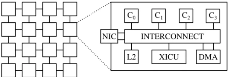
Manycore architectures are architectures containing from a few tens to thousands of cores integrated on the same chip. Such architectures use simple cores in order to maximize the performance per Watt ratio [2]. They are typically clus-tered, the clusters being connected together via a Network-on-Chip [3], [4]. Each cluster (figure 1) usually contains one or several cores and a few peripherals, connected over a fast local interconnect. Apart from the performance per Watt, the biggest advantage of manycore architecture is their inherent redundancy, which allows both power dissipation reduction by dynamically turning off idle cores, and fault-tolerance through deactivation of faulty cores while using the remaining functional ones.
Manycore architectures vary in the way the cores can communicate, either inside a cluster or between two different clusters. Some architectures use specialized interfaces (e.g [5]) or dedicated hardware buffers to make two cores communicate, while some others support shared memory. Among the shared memory architectures, some support hardware coherence [6], [7] while others do not [8].
We believe that a manycore architecture should provide shared memory with hardware cache coherence in order to support general purpose operating systems. In a cloud platform context, it is true that we need not allocate all of the resources to a single user, but providing a minimum number of cores is essential to have a sufficient computational power since cores are simple. Besides, running a general-purpose multicore operating system almost requires to have hardware coherence. The TSAR architecture [1] described in section IV and used as a baseline for this work thus provides shared memory with hardware cache coherence.
INTERCONNECT
C0 C1 C2 C3
XICU DMA
L2 NIC
Figure 1. Manycore Architecture
B. Logical Partitions and Dedicated Hardware
A logical partition is an independent operating environ-ment, consisting of a subset of the architecture processors, memory and I/O devices, and running a guest operating system. The guest operating system is a virtualized oper-ating system, running above some kind of hypervisor. As such, a logical partition is one type of virtual machine [9]. Logical partitioning is used in some virtualized environments requiring high insurance, such as separation kernels [10], [11]. Commercial services using architecture partitioning for virtual machines include the Infrastructure as a Service (IaaS) provided by IBM [12], [13], or Hitashi embedded virtualization technology [14].
Logical partitions can either have dedicated processors or share them. Dedicating hardware to specific guest operating systems has the drawback of rigidity and non optimal use of the resources. However, it comes with a big advantage: by dedicating these resources to the guest operating system, the hypervisor does not necessarily need to interact with the latter, therefore minimizing risks of being compromised. This technique is known as hypervisor disengagement [15]. Besides, this reduced interaction in turn results in a low performance overhead for the virtual machine compared to a non virtualized execution of the operating system.
C. Hypervisors and Security Concerns
Operating system virtualization [16] is a technique which allows to execute an unmodified operating system on a part of an architecture. A hypervisor is generally used to manage the different virtualized operating systems [17], [18]. It is a software agent located between the hardware and the virtu-alized operating systems, and its role is to allocate hardware resources to guest operating systems. As such, it is a security critical point, since every breach in the hypervisor can lead to:
• unauthorized reads of data of a virtual machine
(con-fidentiality violation);
• unauthorized modification of pieces of data of a virtual machine (integrity violation);
• information leakage – data left in memory or
hard-ware components which can be exploited by another malicious virtual machine.
Thus, the hypervisor must be part of the Trusted Computing Base (TCB), i.e. the trusted elements in the system. This is why the hypervisor should remain as small as possible, so as to minimize the risks of it being compromised. [9] defines two properties for measuring the hypervisor sensitivity to attacks: small footprint and reduced interaction. The footprint is traditionally measured in lines of code (LoC), fewer lines meaning fewer bugs in average, and thus fewer possibilities for an attacker to exploit a flaw. Using hardware virtualization ex-tensions, hypervisor can be as small as 4K LoC [19], whereas hypervisor implementing all the virtualization mechanism can reach 100K LoC [20].
Interactions between the hypervisor and a guest operating system happen at launch and shutdown, and every time a virtual machine requires a service from the hypervisor, for example during an I/O access. Hypervisor disengagement allows to limit interactions at their minimum, i.e. launch and shutdown, thus reducing the possibilities for an attacker to exploit a bug in a hypervisor function.
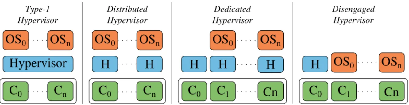
Hypervisors can be classified into several categories. In
traditional T1 hypervisors (figure 2), a single hypervisor
instance manages all the resources, allocates them, and inter-acts frequently with the guest operating system. For example, every I/O interrupt triggers a context switch to the hypervisor. Other interactions may be required, in particular for memory management if there is no specific hardware extensions, which include an additional privilege mode to the CPU to the user and kernel modes, combined with a MMU extension to translate machine addresses to another layer called physical addresses.
C
0C
nC
0C
nHypervisor
OS
0OS
nOS
0OS
nH
H
Type-1 Hypervisor Distributed Hypervisor Dedicated HypervisorC
0Cn
H OS
0OS
nC
1 Disengaged HypervisorC
0Cn
H
OS
0OS
nC
1H
H
Figure 2. Different types of Hypervisors
Such hypervisors thus need many hardware modifications to have reduced interactions, and still are not completely isolated. Distributed hypervisors [21], [22] consist of having sev-eral hypervisor instances, each in charge of a subset of the architecture (figure 2), typically at the allocation granularity. As for traditional T1 hypervisors, such hypervisors are in charge of the underlying hardware and provide an interface to access I/O devices, thus making a reduced interaction with the virtual machine not possible.
Dedicated hypervisors [23], [24] run on dedicated cores and manages the operating systems running on other cores.
Disengaged hypervisors [15] are a type of dedicated hypervisor which limit the runtime interaction with the vir-tual machines by letting the latter directly in charge of the underlying hardware. This allows for improved security and performance. This type of hypervisors can have both a small footprint and a reduced interaction, but usually require hard-ware extensions to isolate the running virtual machines.
Blind hypervisors [25] are a type of dedicated and dis-engaged hypervisor which tend to even more minimize the runtime attack surface compared to disengaged hypervisors, by disallowing the hypervisor access to hardware resources of a virtual machine once it is started. Not only are the interactions between a virtual machine and the hypervisor not required, but they are impossible. If the hypervisor can still stop a running virtual machine, it cannot access any of its data during of after its execution. Blind hypervisors also usually require hardware extensions to achieve their goal.
D. Memory Isolation
In order to enforce isolation between the different vir-tual machines, a hypervisor can use a third address space comprising physical addresses (or host physical addresses). The translation mechanism must ensure that all the physical addresses obtained for a virtual machine can only target memory or devices located inside the cluster allocated to that virtual machine. Traditionally, this translation is made via the Memory Management Unit (MMU) inside the first-level cache [26], [27], [28] but it requires that the hypervisor and the virtual machine share cores. For a disengaged hypervisor, this is thus impossible. Another technique is to add a MMU with pagination between the NoC and each initiator on the latter. However, this comes with several drawbacks: first a MMU generally uses a Translation Lookaside Buffer (TLB) to speed up address translation. This implies a non negligible
hardware overhead, including the logic to manage the TLB misses. Second, the hypervisor must create the page table for the memory allocated to a virtual machine and store it into a memory space non accessible by itself nor by any virtual machine. This cannot be done entirely in software and therefore requires the introduction of specific hardware elements. Third, a MMU is slow to perform address translation because of the TLB misses overhead.
Overall, this solution is not entirely satisfying, and given the need for a hardware extension, a technique similar to segmentation will be investigated to perform physical memory isolation [29].
III. DESIGNCHOICES
We target highly secure environments with redundant iso-lation mechanisms, in particular physical isoiso-lation between virtual machines, guaranteed by the hardware.
To prevent two virtual machines to interact, our solution obviously dedicates cores to virtual machines.
Hypervisor disengagement is crucial to our solution since we target a highly secure platform. To this end, we consider dedicated architecture extensions. These extensions, which should remain minimal, allow to leverage the small interac-tions between the virtual machine and the hypervisor. Our solution uses a small dedicated disengaged blind hypervisor. This hypervisor is not able to access data inside clusters, nor change the allocated elements of a virtual machine once the primary configuration is made. Indeed, the reconfiguration is only possible after completion of a procedure comprising the deletion of all memory banks contents.
We believe that dedicated hypervisors are particularly suited to manycore architecture since the high number of cores mitigates the impact of dedicating cores to the hypervisor. Ded-icating cores to the hypervisor has another indirect advantage: it lets the possibility to reuse the user and kernel modes of the processor to dissociate critical parts of the hypervisor from the others, by using the kernel mode for critical parts. As an example, our hypervisor uses a shell to execute commands for virtual machines creation. We do not want that a buffer overflow in the shell can result in a possible corruption of the hypervisor sensitive data, what is possible by putting the shell related parts of the hypervisor in the user side. Similarly to what happens in an operating system, critical parts of the hypervisor are called via syscalls, which are the only parts to be included in the TCB.
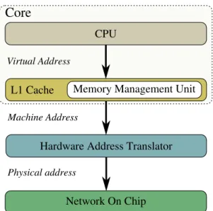
Core
CPU
L1 Cache Memory Management Unit
Hardware Address Translator
Network On Chip Virtual Address
Machine Address
Physical address
Figure 3. Representation of the Three Used Address Spaces: Virtual, Machine and Physical
The blind and disengaged parts are carried out by means of address translation (figure 3): our translation mechanism operates at the output of the first-level cache, before the intra-cluster crossbar and is performed by a hardware component called Hardware Address Translator (HAT). This module acts as a wrapper for initiators inside a cluster and plays the same role as a MMU for segmentation, although it differs in several ways compared to the latter: it uses topology information in order to perform address translation. The price to pay for this design choice compared to pagination is a lack of flexibility in hardware resource allocation – since a user launching a virtual machine can only allocate a multiple of clusters – but from a security point of view, it allows to physically isolate clusters of distinct virtual machines by the means of address routing (with the exception of some peripherals, which will be discussed later). In summary, our proposed solution for physical isolation is a simple and fast segmentation module, whose downside is the translation granularity, but which does not come as a problem with our design choices.
HAT
Disabled EnabledHAT
Configurable Not Configurable
Activation
Deactivation
Figure 4. HAT StatesFigure 4 shows the alternating two states of the HAT. When the processor starts, the HATs are in the disabled state in which they provides an identity translation from machine to physical. In this state, they can be configured by any core; practically, it can only be an inactive core, i.e. a core not already dedicated to the hypervisor or a running virtual machine. Then, during the boot sequence of the virtual machine, the HATs are configured by one of the virtual machine cores. Finally, the HATs are activated by their own core, and switch their state to enabled. Once in the enabled state, they cannot be configured anymore; a new configuration will only be possible after the
LOCAL - C ROSS BAR L1/L2 - NETWORK XRAM - NETWORK XRAM XRAM Target Port Initiator Port System-on-chip Hardware Interrupt P0 (L1) P1 (L1) P2 (L1) XICU DMA IOB L2 P3 (L1) P0 (L1) P1 (L1) P2 (L1) P3 (L1) XICU DMA L2 LOCAL - C ROSS BAR I/O - NET WORK IOC IOPIC T TY BROM I/O Cluster Cluster (0, 0) Standard Cluster
Figure 6. The TSAR Architecture
HAT deactivation, which is coupled to the virtual machine shutdown.
Another problem, which has not been covered until now, is cache coherence. Since L1 caches contain machine addresses, and L2 caches physical addresses, coherence requests need a translation mechanism. The latter is also achieved by our HAT module.
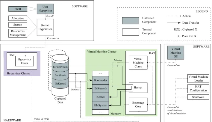
The global infrastructure of our designed solution is pre-sented in figure 5, separating trusted from untrusted compo-nents. The disk is encrypted for security purpose, and major cyphering/deciphering operations are handled by a hardware coprocessor called HCrypt.
IV. EXISTINGHARDWARECOMPONENTS AND
MODIFICATIONS
A. The TSAR Architecture
Figure 6 and 7 show an overview of the TSAR architecture. It is a clustered architecture with a 2D mesh topology using a Network-on-Chip. The cluster with coordinates (0, 0) addi-tionally contains an access to I/O cluster via an Input/Output Bridge (IOB). The I/O cluster contains all the I/O peripherals. The TSAR architecture is designed to support up to 16 × 16 clusters; in particular, 8 bits in the address are reserved for address routing (4 for X and 4 for Y ).
All clusters contain:
• 4 MIPS32 cores with their paginated virtual MMU
and their first level caches, split between instructions and data. The L1 cache coherence is managed entirely in hardware. Misses in the TLB are also handled by the hardware.
• 1 second level (L2) cache, which is in charge of a
Virtual Machine Cluster MachineVirtual OS Kernel Hypervisor User Hypervisor Shell Allocation Startup Ressources Management HAT Hypervisor Cores Hcrypt Memory Hypervisor Cluster SOFTWARE HARDWARE Syscall HAT Virtual Machine Cores Bootstrap Core Cyphered Disk FileSystem Kernel E(Kernel) Bootloader .... SOFTWARE Virtual Machine Loader HAT Configuration Shutdown Executed on Executed on Executed at start/shutdown of virtual machine Wakes up (IPI) Initiates Initiates .... LEGEND E(X) : Cyphered X Untrusted Component Trusted Component Action Data Transfer X : Plain text X E(Kernel) Bootloader E(FileSystem)
Figure 5. Designed Solution Infrastructure
13 14 15 8 9 10 11 4 5 6 7 0 1 2 3 12
Cluster (0, 0) Standard Cluster
X Y
Figure 7. The 2D Mesh Representation of the TSAR Architecture
particular, it is responsible for the coherence of the copies in L1 caches for the lines contained in its segment.
• 2 internal peripherals: an interrupt controller including timer functions (XICU) and a Direct Memory Access controller (DMA). These peripherals are called repli-cated peripherals.
• A local crossbar interconnecting these components
with an access to the global network (L1/L2 Network)
via a router.
The I/O cluster additionally contains:
• A terminal controller (TTY).
• A hard-drive disk controller (IOC).
• A Programmable Interrupt Controller (PIC), able to
convert a hardware interrupt into a software one.
• A Read Only Memory (BROM) containing the reset,
startup and shutdown codes, so that these critical codes cannot be modified.
• A I/O network interconnecting these components with
an access to the RAMs network (XRAM network) and the global network via the IOB.
This architecture will be used as a base for our secured architecture proposal, with substantial modifications in order to meet the motivated requirements.
B. Hardware Modifications to the TSAR Architecture
This section presents in details the hardware modifications proposed by our solution in order to isolate two virtual machines by adding hardware extensions.
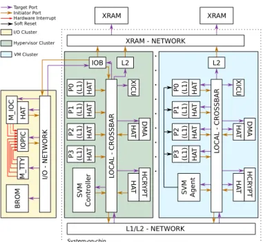
Figure 8 shows an overview of our proposed secured architecture with the hardware extensions.
The translation from machine addresses to physical ad-dresses is performed by the HAT module, which is configured once by the hypervisor at the start of an operating system and placed behind each initiator in the architecture – as well
HA T LOCAL - C ROSS BAR L1/L2 - NETWORK XRAM - NETWORK XRAM XRAM Target Port Initiator Port System-on-chip Hardware Interrupt HA T HA T HA T P0 (L1) P1 (L1) P2 (L1) XICU DMA HCR YPT HA T HA T IOB L2 P3 (L1) HA T HA T HA T HA T P0 (L1) P1 (L1) P2 (L1) P3 (L1) XICU DMA HCR YPT HA T HA T L2 LOCAL - C ROSS BAR I/O - NET WORK HA T M_IOC IOPIC M_T T Y BROM I/O Cluster Hypervisor Cluster VM Cluster SVM Contr olle r SVM Agent Soft Reset
Figure 8. The TSUNAMY Architecture
cores as replicated DMAs. The latency taken for translating a machine address through the HAT is 2 cycles (pipelined in case of consecutive requests), with only one cycle for the translation mechanism.
A physical address outgoing from a HAT can be one of the followings two types:
• an address targeting a module included in a cluster of
the same virtual machine: memory via the L2 cache or a replicated peripheral (DMA or XICU); this is the standard case, and it will be referred to as an internal access
• an address targeting a peripheral outside the virtual
machine, namely the disk controller or the TTY. This case will be referred to as an external access. Figure 9 shows an overview of the HAT operation depend-ing on the type of address to translate.
Translate Internal Access Emit Physical Address Receive Machine Address Lookup DevAccess Table Entry Found Entry not Found
Figure 9. Hardware Address Translator Overview
The hardware cost involved for the HAT is 130 bytes of memory (85 bytes for internal registers, 5 bytes for configu-ration registers, and 8 bytes for each of the 5 external access entries), and two FIFOs of depth 2 for buffering transactions, with widths of 112 and 56 bits.
C. Internal Accesses
The physical address space is split on the clusters in such a way that the most significant bits (MSB) define the cluster coordinates, as this is the case with the TSAR architecture. The machine addresses provided by the MMU are 40-bit but only the first 32 bits are relevant: in fact the 8 MSB are set to 0 (ETX and ETY fields) because the operating system used here is 32 bits. Thus, the translation mechanism achieved by the HAT only consists in computing the coordinates of the destination cluster of the virtual machine and writing it in the 8 MSB of the physical address. Figure 10 and 11 illustrate how the HAT module works with a 16-cluster architecture.
4 2 4 4 2 4 8 3 6 8 1 4 1 OFFSET VPN MXMY OFFSET OFFSET HAT MMU Virtual Address (32 bits) Machine Address (40 bits) Physical Address (40 bits) PX PY 0 0 ETX ETY 4 2 4 0 1 0 3 MX: 1 bit MY: 1 bit PX: 4 bits PY: 4 bits ETX: 4 bits ETY: 4 bits ... ... 4 8 7 0 1 0 0 0 0 0 1 0 0 0 0 0 0 0 0 4 8 7 ... ... 0 0 0 0 0 0 0 1 0 0 0 0 0 0 1 1
Figure 10. Translation from Machine to Physical Address for an Internal
Access
In this example, a virtual machine is running on clusters (0,2), (0,3), (1,2) and (1,3) of the platform. The X size of the virtual machine is 2 and the Y size is 2. The MX field represents the number of bits needed to code the X size of the virtual machine: in our case, only 1 bit is needed. The MY field is the same as MX for the Y dimension (1 bit too).
A core sends the virtual address 0x83681424 which is translated by the MMU into the machine address 0x41487424. In a virtual machine with 4 clusters, the machine address starting with 0x4 is located in the cluster (0,1), containing the machine address range <0x40000000–0x7FFFFFFF>. In our example, the cluster (0,1) of the virtual machine is the cluster (0,3) of the platform, with a physical address range <0x0300000000–0x03FFFFFFFF>. Therefore, the HAT will provide the translation of an address belonging to the cluster (0,1) of the virtual machine to an address inside the cluster (0,3) of the platform.
D. External Accesses
The hypervisor software is not involved in the accesses made by virtual machines to peripheral devices. The differ-entiation between an internal access and an external access is made via a lookup into a DevAccess table. If the machine address matches an entry into the table then the HAT acts similarly as a segmentation mechanism. This is the case if the device targeted by the address is actually allocated to the virtual machine. This DevAccess table contains several entries, each one containing two pieces of information:
• the base physical address of the segment associated to
the device (BASE PA);
• the two’s complement of the size in bytes of this
00 10 20 30 01 11 21 31 02 12 22 32 33 23 13 03 00 00 10 01 11 Cluster Offset MY MX MYL MXL MA Cluster Offset PY PX PYL PXL PA f (MX,MY) 00 01 02 03 10 11 12 13 20 21 22 23 30 31 32 33 00 00 01 10 11 f (MX,MY) Physical Address Space
Machine Address Space
Figure 11. Translation Overview
This choice was made over the base/length attributes of the segment, requiring two integer comparators, so as to keep the HAT as light as possible.
For simplicity reasons, the I/O cluster is chosen as the cluster running the hypervisor, although it could be any other cluster.
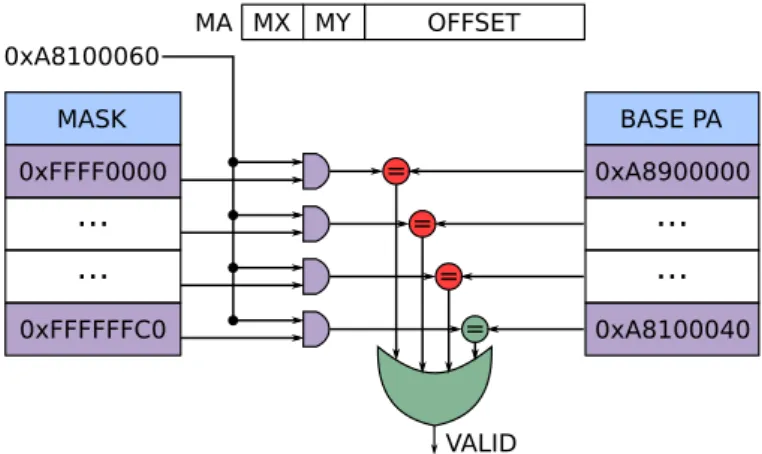
Figure 12 provides an example of the way the HAT performs a device access.
MA MX MY OFFSET MASK 0xFFFF0000 0xFFFFFFC0
...
...
BASE PA 0xA8900000 0xA8100040 = = = = 0xA8100060...
...
VALIDFigure 12. Translation from Machine to Physical Address for an External
Access
In this example, the virtual machine is deployed on 4 clusters, so the fields MX and MY are 1-bit wide. The machine address emitted by the core is 0xA8100060. This address is then masked with the two’s complement contained in the HAT table and compared with the base physical addresses of all devices associated to the virtual machine. If one comparison is true then the machine address is valid and the request is sent to the target device. In contrast, if no comparison is true then the request is considered as an internal access, and therefore will be issued with a physical address contained in the clusters allocated to the virtual machine. If this address is not valid, i.e. that initially it was targeting an unauthorized device, it will be routed to the default component of the cluster and an error will be returned to the core as a bus error; this error indicates to the operating system that the core tried to access a non-existing address.
V. HYPERVISORBASICFUNCTIONALITIES
A. Clusters Allocation
When the user makes a request to start a virtual machine, the hypervisor allocates the requested number of clusters for this virtual machine, and for that must find a free set of clusters. Furthermore, in order to avoid that a given virtual machine can interfere with another, we made the choice to allocate only a contiguous and convex set of clusters to a virtual machine. Indeed, since two virtual machines share the same global network (L1/L2 network), a lot of traffic generated by a certain virtual machine could potentially degrade the performances of another virtual machine (this is discussed in section VI-F).
Figure 13 illustrates how a non-convex allocation can result in a traffic interference between two virtual machines.
Free Cluster I/O Cluster VM-1 Cluster VM-2 Cluster Router Overloaded Router Request from VM-1 Request from VM-2
Figure 13. Non-Convex Clusters Allocation
This choice also has two other advantages: first, it allows to give the operating system a simple 2D-mesh topology which corresponds to reality, therefore respecting its locality heuristics; second, it requires few data to represent an allocated set of clusters, which is important given that the hardware will be involved in resource management. Of course, this implies that some values for clusters cannot be treated well (typically high prime numbers), but we can suppose that the demanded values are reasonable, either because only some of them are proposed to clients or because a higher level layer “rounds up” the demanded value to match a proposed value.
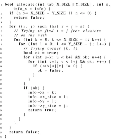
Clusters Allocation Algorithm.The algorithm for clusters allo-cation is described in figure 14. It is composed of two parts. In the first part (line 5), we enumerate all the (x, y) values so that x × yequals the required number of allocated clusters n; This can be done in two ways: either enumerate all x values, then compute y = n/x and check that x × y = n; or have a pre-computed table of possible configurations (possibly indexed by n), which makes it easier to explore the best configurations first (i.e. those for which x and y are close). In the second part, we check all possible placements (lines 8-9) and check the availability of such placements (lines 11-18).
B. Peripherals Allocation
The external access mechanism provided by the HAT allows a virtual machine to access specific channels of the IOC and the TTY. Each channel contains a set of addressable
1 bool a l l o c a t e ( i n t t a b [ X_SIZE ] [ Y_SIZE ] , i n t n , i n f o _ s ∗ i n f o ) { 2 i f ( n >= X_SIZE ∗ Y_SIZE | | n <= 0) { 3 return f a l s e ; 4 } 5 f o r ( ( i , j ) such t h a t i ∗ j = n ) { 6 / / T r y i n g t o f i n d i ∗ j f r e e c l u s t e r s 7 / / on t h e mesh 8 f o r ( i n t k = 0 ; k <= X_SIZE − i ; k ++) { 9 f or ( i n t l = 0 ; l <= Y_SIZE − j ; l ++) { 10 / / T r y i n g c o r n e r ( k , l ) 11 bool ok = true ; 12 f o r ( i n t u=k ; u < k+ i && ok ; u ++) { 13 f o r ( i n t v= l ; v < l + j && ok ; v ++) { 14 i f ( t a b [ u ] [ v ] != 0) { 15 ok = f a l s e ; 16 } 17 } 18 } 19 i f ( ok ) { 20 i n f o −>x = k ; 21 i n f o −>x _ s i z e = i ; 22 i n f o −>y = l ; 23 i n f o −>y _ s i z e = j ; 24 return true ; 25 } 26 } 27 } 28 } 29 return f a l s e ; 30 }
Figure 14. Clusters Allocation Algorithm.tabis the cluster occupation table,
nthe number of clusters required, andinfothe returned informations
registers independent from the others. Each channel of the IOC also contains a hard drive disk comprising the operating system instance: image of the operating system, its file system, and its associated bootloader. Only one of each operating system instance can be run at a time, and in our prototype it is selected in the hypervisor command to launch a new instance.
The association between an instance I and the allocated clusters is used by the hypervisor to configure the PIC: the interruptions outgoing from a channel are routed to the PIC, which must trigger software interrupts towards an XICU located in a cluster allocated to the same instance I, which in turn converts it to a hardware interrupt.
C. Cyphered Disk and File System
In our architecture, the disk images, comprising the kernel and the file system, are cyphered with a key which is specific to the user and which can be obtained from a password. During a virtual machine lifetime, this key is stored inside the memory of that virtual machine. The kernel needs to be deciphered by the bootloader at the start of the virtual machine, and the file system is deciphered by the kernel every time a new block is read from the hard drive disk. Similarly, every time a block is written back on the disk, it needs to be cyphered with the key. All the major cryptographic computations are made by a secure cryptographic coprocessor integrated into the architec-ture, and called HCrypt [30].
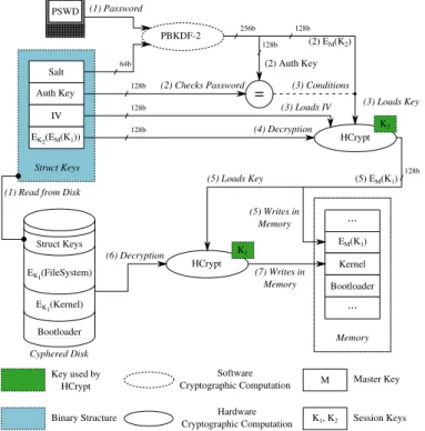
Figure 15 shows in details the procedure required to create the cyphered disk. The first step is to encrypt the kernel and the file system. For this, the HCrypt is requested to generate
a key K1: this key is the main user key used for encryption
of the different elements of the disk image (steps 1, 2, 3). The second step is to create a binary structure containing
the elements allowing to retrieve the cryptographic key K1
when running the bootloader. For this, two values are randomly generated: an Initialization Vector (IV) and a Salt. The Salt is combined with the user password in the PBKDF-2 [31] cryptographic function, which outputs a 256-bit key. This key is then separated into two parts: the 128 most significant bits are used as an Authentication Key (Auth Key) while the 128 least significant bits are used as a session key EM(K2)
for encrypting the key K1. The 128 least significant bits are
called EM(K2) because when a session key is loaded into
the HCrypt, the latter expects to receive an encrypted key and internally decrypts this key with its master key. Similarly, the HCrypt generates only encrypted session keys, so that reading this key alone is not sufficient to decipher data. Then the IV
and EM(K2) are loaded in the HCrypt and the session key
EM(K1)can be encrypted. The HCrypt outputs the encrypted
session key K1: EK2(EM(K1)). This encrypted key is then stored in a binary structure with the IV, the Auth Key and the Salt (steps 4, 5, 6, 7).
This binary structure, called Struct Keys, is finally stored in the disk image, and will be used by the bootloader to allow the disk decryption (8).
IV Salt Auth Key EK2(EM(K1)) Struct Keys IV Salt Kernel FileSystem EK1(Kernel) Bootloader EK1(FileSystem) Struct Keys Cyphered Disk HCrypt PBKDF-2 HCrypt K2 K1 64b 256b 128b 128b 128b 128b 128b EM(K2) (5) Auth Key EM(K1) (7) EK2(EM(K1)) (6) Get Key (5) Loads IV (5) Loads Key (1) Generates Key (K1)
(2) Encryption (3) Writes on Disk
(8) Writes on Disk
(4) Password
(4) Generates Random Salt
(4) Generates Random IV M K1, K2 Key used by HCrypt Binary Structure Software Cryptographic Computation Hardware Cryptographic Computation Master Key Session Keys PSWD (6) Encryption
Figure 15. Cyphered Disk Creation Procedure
Figure 16 shows the procedure required for the decryption of the cyphered disk, which takes place at the start of a virtual machine. The decryption procedure of the disk is shown in Figure 16, and must be performed by the bootloader.
The Struct Keys contained in the hard drive disk is read once the user password is entered. The bootloader executes the PBKDF-2 function with the Salt contained in the structure and the entered password. The 128 most significant bits are then compared to the Auth Key of the Struct Keys to check the password validity. If the entered password is wrong, then the bootloader stops. Otherwise, EM(K2) is loaded into the
HCrypt as a session key, and the IV is loaded as well, allowing to decipher EK2(EM(K1))(steps 1, 2, 3, 4).
Once deciphered, EM(K1)is loaded inside the HCrypt and
stored in memory, for the operating system be able to decipher other hard drive disk data – e.g. applications or images – without asking for the user password every time (step 5).
Finally, the bootloader decrypts the kernel and stores it in memory, after what it is able to execute the boot of
the operating system (steps 6, 7). The user key EM(K1) is
unloaded from the HCrypt after every operation.
IV Salt Auth Key EK2(EM(K1)) Struct Keys HCrypt HCrypt PBKDF-2 K2 K1 64b 128b PSWD (2) EM(K2) (2) Auth Key (5) EM(K1) (4) Decryption (3) Loads IV M K1, K2 Key used by HCrypt Binary Structure Software Cryptographic Computation Hardware Cryptographic Computation Master Key Session Keys Kernel ... Bootloader EM(K1) Memory ... = 128b 128b 128b 128b 256b (3) Conditions (3) Loads Key 128b (5) Loads Key (6) Decryption (7) Writes in Memory (5) Writes in Memory (1) Password (2) Checks Password
(1) Read from Disk
EK1(Kernel)
Bootloader
EK1(FileSystem)
Struct Keys
Cyphered Disk
Figure 16. Cyphered Disk Decryption Procedure
D. Virtual Machine Boot Procedure
The virtual machine boot procedure can be divided in five steps:
• (1) Clusters allocation;
• (2) Channel allocation for external peripherals;
• (3) Generation of the virtual machine architecture
description;
• (4) Isolation of the clusters allocated;
• (5) Awakening of the cores allocated: this must be
done by the hypervisor, by sending an Inter-Process Interrupt (IPI).
The problem with this sequence is located in the steps 4 and 5: since the hypervisor is executing on another cluster, it cannot send an IPI to an isolated virtual machine. However, the isolation in step 4 cannot be done after step 5 since it would mean that a virtual machine starts in a non isolated environment.
The main idea for solving this problem is to make each core contained in the clusters allocated to the future virtual
machine execute a hypervisor code (startup code) whose role is to configure the HAT to isolate the virtual machine.
Figure 17 shows in more details the steps of the boot process. wait wait barrier Activation of HAT OS Bootloader Loading of OS bootloader and kernel Routing of
interruptions Waking up
C0-VM Jump at startup code
Check of C0-VM Code executed by the VM Core hypervisor C-HYP Clusters Allocation Device-Tree Generation Core virtual machine C0-VM Loading of Device-Tree Configuration of VM HATs code executed by C0-VM only
Boot Virtual Machine Software Procedure Kernel Code of
Hypervisor User Code of Hypervisor
C-HYP: Hypervisor Core C0-VM: VM Bootstrap Core RHA : Remote Hat
Activation Start Request
from User
Configuration of VM peripherals
Figure 17. Virtual Machines Boot Procedure
First, a user requests the hypervisor to deploy a new virtual machine via the hypervisor shell. The user specifies which operating system instance he wants to boot and the size, in clusters, desired for its virtual machine. The hypervisor core, Chypthen searches for a set of free clusters and allocates them
to the new virtual machine. After that, the hypervisor generates a Device-Tree binary file representing the architecture on which the virtual machine is deployed – number of memory banks, cores and channels allocated to the virtual machine. The hypervisor routes the interruption lines of the peripherals associated to the virtual machine and then wakes up the
Inter-Process-Interrupt.
Once awakened, the C0 − V M jumps to the startup code. Since it is the first core to execute this code, it must perform general configurations.
Second, it must load from the disk of the virtual machine the encrypted bootloader and kernel of operating system. Then, he must copy the description of the architecture of the virtual machine created by the CHypcore in the memory of the virtual
machine.
Third, it must configure all the HATs of the virtual ma-chine: those of cores, DMA controllers and external periph-erals. For the peripherals, the C0−V M must also activate the
HATs after configuration.
Finally the C0−V M activates its own HAT and jumps to
the bootloader of the operating system.
One of the actions of the bootloader is to ask the user password and then decrypt the kernel of the operating system as see in the figure 16 at the section V-C.
The other cores of the virtual machine are woken up by the operating system at the end of the bootloader, and only have to activate their HAT.
E. Virtual Machines Shutdown Procedure
Our proposed virtual machine shutdown mechanism aims at proposing an interface for stopping a running virtual machine, accessible either by the hypervisor, or by the virtual machine itself. We do not make assumptions here on the reasons why the hypervisor would terminate a virtual machine, but provide this service and guarantee that once called, this procedure will terminate the virtual machine and clear all of its footprints. In our prototype, a hypervisor shell command allows to call this procedure, as well as a system call added in the operating system we use.
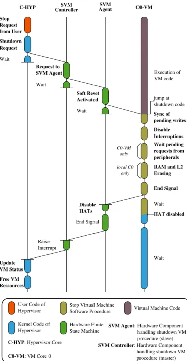
The shutdown procedure is based on two hardware modules and a software procedure. The two hardware modules allowing to achieve the shutdown procedure are the Shutdown Virtual Machine Controller (SVM Controller) and the Shutdown Vir-tual Machine Agent (SVM Agent). They guarantee that the virtual machine will be stopped at the end of the process.
The SVM Controller is the master module, seen by the hypervisor, and which can initiate the shutdown procedure. The SVM Controller delegates to the SVM agents the tasks required for the shutdown. SVM Agents are replicated in all the clusters, except the one running the hypervisor.
Figure 18 shows the steps required for the shutdown of a virtual machine. Four entities are involved: the core CHyp,
the SVM Controller, SVM Agents and the cores in the virtual machine.
First, the hypervisor sends a request to the SVM Controller indicating the instance number of the virtual machine he wants to stop. The SVM Controller checks the virtual machine state, and computes which SVM Agents it must contact. Then, it sends a message to these SVM Agents in charge of the virtual machine. The SVM Controller is thus a priori able to access to the devices of all virtual machines, but the hardware guarantees
Hardware Finite State Machine
Virtual Machine Code Stop Virtual Machine
Software Procedure Kernel Code of
Hypervisor User Code of Hypervisor
C-HYP: Hypervisor Core C0-VM: VM Core 0
SVM Controller: Hardware Component handling shutdown VM procedure (master) SVM Agent: Hardware Component
handling shutdown VM procedure (slave) Sync of pending writes C-HYP Shutdown Request C0-VM RAM and L2 Erasing Stop Request from User SVM Controller Wait Soft Reset Activated HAT disabled jump at shutdown code Wait pending requests from peripherals End Signal C0-VM only Wait Wait Raise Interrupt Update VM Status SVM Agent Request to SVM Agent Wait Wait Disable HATs End Signal Free VM Ressources Execution of VM code local C0 only Disable Interruptions
Figure 18. Virtual Machine Shutdown Procedure
that the only addresses it can emit are those from the SVM Agents.
When the SVM Agents receive the message from the SVM Controller, they activate the Soft Reset signal. This signal is a wired signal between a SVM Agent and all the cores inside the same cluster. This makes cores to jump at their reset address (0xBFC00000 for MIPS cores).
The first instructions in the reset code check the cause of the reset via the processor status register. If the cause is a soft-reset, the core executes a specific hypervisor code (shutdown code) in order to stop the virtual machine.
The first instructions of the shutdown code synchronize pending writes, i.e. they ensure that all memory accesses of
0 0.2 0.4 0.6 0.8 1 1.2
FFT Histogram Kmeans Convol
Execution t
imes for Tsunamy normaliz
ed
w.r.t. times with TSAR
1 core 4 cores 8 cores 16 cores 32 cores
Figure 19. Execution Times for Tsunamy Normalized w.r.t. Times with TSAR
the virtual machine outgoing from cores are completed. Then, it ensures that devices have finished all their pending requests, e.g. currently undergoing disk accesses. This is because we have to make sure that disk accesses are complete before freeing the memory of the virtual machine, otherwise it could lead to information leakage.
Then, this code must clear the memory banks allocated to the virtual machine, so as to ensure the privacy property of the virtual machine data. Finally, it must invalidate the content of all L2 caches contained in the clusters allocated to the virtual machine. This invalidation must be done to avoid memory coherency issues.
Once this shutdown code is executed, the cores of the virtual machine send a signal to the SVM Agent of their cluster, indicating that the procedure is completed, and wait for the other cores to finish. Once the SVM Agent receives the signals from all its cores, it deactivates all the HATs in the virtual machine: those of cores, DMAs and allocated peripherals. Once all the HATs are deactivated, the SVM Agent sends a message to the SVM Controller indicating that the shutdown of the cluster is done. After this step, the HATs can anew be configured by the hypervisor.
When the SVM Controller receives a message from all the SVM Agents associated with the virtual machine, it raises an interrupt to the hypervisor in order to notify that the virtual machine has been stopped. The hypervisor updates the status of the virtual machine and its allocation information, thus allowing the clusters to be allocated for another virtual machine.
As this procedure does not need the cooperation of the virtual machine, it can potentially be used as an emergency shutdown by the hypervisor. The SVM Controller is simply seen by the virtual machine as a standard device. A channel is then allocated in the SVM Controller for every running virtual machine, like for other devices (e.g. hard drive disk).
The hardware cost required for one SVM Agent is 51 bytes of memory (47 bytes for internal registers and 4 bytes for configuration registers), and it is 34 + N × 5 bytes for the SVM Controller (34 bytes for internal registers and 5 bytes for each of the N configuration entries), where N is the maximum number of running virtual machines on the platform – typically the number of clusters.
VI. EXPERIMENTALRESULTS ANDDISCUSSION
The architecture is described in SystemC at the cycle-accurate level using the SoCLib components library [32]. Oper-ating system instances are run via a hypervisor terminal, which also allows to switch between the displays of all instances. A. Applications
Applications used for evaluations are FFT from the Splash-2 suite [33], Histogram and Kmeans from the Phoenix-Splash-2 benchmark suite [34], and Convol, which is an image filtering program performing a 2-dimensional convolution filter. Table I shows the configuration for each application.
Table I. APPLICATIONSPARAMETERS
Application Input Data
Histogram 25 MB image (3,408 × 2,556)
Convol 1,024 × 1,024 image
FFT 218Complex Points
Kmeans 10,000 points
All these benchmarks have been run over an operating system called ALMOS [35], which is developed in our lab-oratory. It is a UNIX-like research operating system dedicated to manycore architectures.
Although we only ran ALMOS instances, we could have used other operating systems such as Linux or NetBSD. Our hardware solution makes no assumption about the operating system used, and the reason for using only one type of operating system is to avoid porting other operating systems on the TSAR architecture (independently from the extensions presented here).
B. Performance Overhead Results
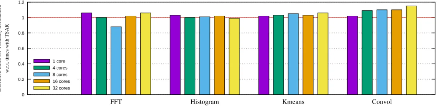
This section evaluates independently three sources of possi-ble overhead: the overhead added by the HATs, the overhead resulting from the simultaneous execution of several virtual machine, and the overhead due to the encrypted file system. HAT Overhead. Figure 19 shows the execution times with the Tsunamy platform for the 4 considered benchmarks. These times are normalized per number of cores and per application w.r.t. times on the TSAR architecture.
This experiment aims at measuring the extra time induced by the addition of HATs in the architecture, this is why a comparison is made with the same configuration on the TSAR architecture. Each application has been run on configurations with 1, 4, 8, 16 and 32 threads, in which each thread was deployed on a dedicated core. For all the configurations, only one virtual machine is deployed on the platform.
For this evaluation, the times measured correspond to the parallel phase of applications, because the way the external devices are accessed is different from the reference TSAR platform. In particular, measuring times corresponding to the load of a file would actually measure the impact of the external I/O cluster – which directly accesses the memory, and requires flushing the L2 caches. Nevertheless, we made these measurements for the whole application runtime, and they barely differ (we discuss them below). The reason why we used a different platform for the TSAR simulations is that the I/O cluster requires 40-bit physical addresses, which are not supported by ALMOS. The Tsunamy architecture, despite having 40-bit physical addresses, allows the execution of 32-bit operating systems thanks to the presence of HATs (c.f. section IV-C). Ongoing work in the hypervisor targets the generation of architecture information in the device-tree format, so as to make it possible to execute Linux and NetBSD on the Tsunamy architecture. This will allow to compare the overhead of the Tsunamy enhancements alone, although they are expected to be very close.
From all the applications, the maximum overhead is 15% on Convol on 32 cores, and the maximum gain happens on FFT with 8 cores. Although the addition of HAT modifies the interleaving of transactions and is expected to produce small variations, we are not currently sure how such a gain is possible, and are investigating this result. However, on average, our solution shows an overhead of 3.2% for all the different configurations and applications, which seems acceptable to us given the security guaranties.
Virtual Machine Interference. These experiments aim at deter-mining whether concurrently executing virtual machine can degrade their respective performance because of interferences on the global network. Because of the topology constraints, we expect this degradation to be null in the absence of external peripheral accesses. In order to verify this, we execute 15 virtual machines in parallel (one per cluster), running the same application on four cores, and compare their execution time with the same application running on a single-cluster virtual machine solely running on the architecture. Figure 21 shows these relative execution times for the whole application, while figure 22 shows the parallel phase of the application.
These results highlight the facts that in the absence of massive I/O accesses, the execution times remain exactly the same. The initialization phase of histogram, which loads a 25MB image, creates a lot of contention on the hard drive disk, which contains only one initiator and target interface (despite having 16 channels). Indeed, all the blocks from the 15 images are serialized when they are copied into memory. Moreover, the load phase represents a non-negligible portion of the total application time, even with a single thread. This result was expected, and to overcome this bottleneck, having several physical disks or a multi-port controller seems the only solution. 0 0.5 1 1.5 2 2.5
FFT Histogram Kmeans Convol
Execution t
imes for 15 virtual mac
hines
normalize
d w.r.t. times with 1 virtua
l machi
ne
Figure 21. Average total execution time of 15 applications running in parallel (1 per VM), compared to a solely running application. Error bars represent the standard deviation for the 15 virtual machines.
0 0.2 0.4 0.6 0.8 1
FFT Histogram Kmeans Convol
Execution t
imes for 15 virtual mac
hines
normalize
d w.r.t. times with 1 virtua
l machi
ne
Figure 22. Average parallel execution time of 15 applications running in
parallel (1 per VM), compared to a solely running application. Error bars represent the standard deviation for the 15 virtual machines.
Cyphered File System. In order to evaluate the overhead in-troduced by the encrypted file system, we made a micro-kernel accessing consecutively 1000 pages from the disk, and compared its execution time with and without the encrypted file system. The page fault with the encrypted file system requires an on-the-fly decryption of the page using the HCrypt, which can process 128 bits of data in 11 cycles. The results show that the version with the encrypted file system is 1.3 times slower. We can note that this worst case scenario is emphasized by the fact that our hard drive disk model has no latency, thus making the deciphering part take a bigger proportion of the page fault resolution than what it would normally with a realistic latency.
Figure 20 shows this overhead, measured in processor cy-cles, for 4 applications (FFT, Histogram, Kmeans and Convol). To this end, we also compare, for a given application and number of cores, the total execution time with the encrypted file system to the same configuration without the encrypted file system. Each application is run with 1, 4, 8, 16 and 32 threads on dedicated cores. Again, only one virtual machine is deployed for all configurations.
For the applications FFT and Kmeans, the introduction of the encrypted file system does not impact performance; in fact,
0 0.2 0.4 0.6 0.8 1 1.2
FFT Histogram Kmeans Convol
Execution t
ime for Tsunamy cyphered file sys
tem
normalize
d w.r.t. times with Tsunam
y 1 core 4 cores 8 cores 16 cores 32 cores
Figure 20. Execution Times for Cyphered File System Normalized w.r.t. Times with Plain Text File System
these benchmarks are not making any access to the hard drive disk, apart from instruction related page faults.
For Convol, the overhead induced by the encrypted file system is on average 1.5%. Even if this application accesses the hard drive disk to load the image to be processed (which takes 2 MB), the loading time of the image only represents a few percentage of the computation time, so the performance degradation remains modest.
For Histogram, the overhead induced by the encrypted file system is larger than with others applications, since the image loading time represents the major part of the application, as the processing is very limited. We note that the overhead decreases with the number of processors used by the applications, what is due to the fact that within ALMOS, the disk accesses are sequentialized. The overhead induced by deciphering the disk – about 3000 cycles per access – is irrelevant compared to the overhead induced by the serialization of disk accesses.
We can thus conclude that our proposed file system en-cryption mechanism does not impact applications which do not access the disk; and for applications using the disk, that the overhead is acceptable.
Other experiments are currently in progress to measure the cost of a software cryptographic solution integrated in the operating system, in order to evaluate if such a solution is prohibitive.
C. Hypervisor complexity
Table II shows the size, in lines of code, of the different parts of our hypervisor implementation. It comprises a total of 3.8K lines of code, excluding comments, which is good regarding the small footprint property. Our hypervisor is sepa-rated into two main parts: the kernel and the user part. In our case, only the kernel part has to be trusted: in particular the critical functions making the HAT configuration, the boot and the shutdown procedures. These functions have in average 140 lines of code.
D. Boot Procedure Results
Figure 23 shows the execution time of the boot procedure of a virtual machine on a variable number of clusters. This time is measured from at the beginning of the sequence, i.e. when the run command is entered on the shell, to the awakening of all cores of the virtual machine. The average time
Table II. HYPERVISORCOMPLEXITY IN LINES OF CODE(LOC)
Function LoC Kernel 2671 Hat configuration 118 Boot procedure 141 Shutdown procedure 163 Shell 739 Total 3811
to boot a virtual machine is 1.6 millisecond for a processor clocked at 1GHz. We can notice that the boot sequence is almost independent from the number of clusters allocated to the virtual machine. This can be explained by the fact that when more clusters are allocated to a virtual machine, the boot mechanism only has to configure a few more components. In the figure 24, we can notice that the majority of the time taken by the boot sequence is for executing the first step of the bootloader (initialization, kernel deciphering, and cores awakening) and for loading into the RAM the bootloader and the kernel. These two steps are totally independent from the size of the virtual machine, thus explaining the almost constant time. In the figure 25, we have suppressed the bootloader step, and we can notice that the device-tree generation and hardware configuration steps are dependent from the size of the virtual machine, but still represent a negligible overall time.
0 0.5 1 1.5 2 0 1 2 4 8 0 0.5 1 1.5 2 Number of cycles (x 10 6 ) Time at 1Ghz frequency (ms)
Number of clusters allocated to a virtual machine
Figure 23. Execution time for virtual machine boot depending on the number of clusters
0 0.2 0.4 0.6 0.8 1 1 2 4 8 Breakdown of
boot procedure normaliz
ed
w.r.t. total ti
me for each configuration
Number of clusters allocated to a virtual machine
Allocation BuildArch Irq Config Loading VM Copy VM Hardware Config Bootloader Other
Figure 24. Breakdown of elapsed time during the boot procedure, depending on the number of clusters
0 0.2 0.4 0.6 0.8 1 1 2 4 8 Breakdown of
boot procedure normaliz
ed
w.r.t. total ti
me for each configuration
Number of clusters allocated to a virtual machine
Allocation BuildArch Irq Config Loading VM Copy VM Hardware Config Other
Figure 25. Breakdown of elapsed time during the boot procedure excluding the bootloader part, depending on the number of clusters
E. Shutdown Procedure Results
Figure 26 shows the execution time of the shutdown pro-cedure of a virtual machine on a variable number of clusters. This time is measured from the beginning of the sequence, i.e. when the stop command is entered on the shell, to the reception by the hypervisor of the interruption resulting from the shutdown of the virtual machine. For this experiment, we used 64MB RAMs for each cluster. The average time to stop a virtual machine is 140 milliseconds. We can notice that the shutdown mechanism is not dependent on the number of clusters allocated to the virtual machine. This is because the shutdown procedure is distributed, and all the clusters work in parallel and clean their own resources. In addition, the shutdown is obviously dependent on the size of the RAM on each cluster: the reset of the memory used by the virtual machine takes 99.9% of the time required to shutdown a virtual machine. As the capacity of the memory increases, this reset can only be longer. The 64 MB used for the experiments are clearly under a real memory size – 1 GB per cluster would be more realistic – but this phase is already parallel and using DMAs, so the only way to speed it up would be to use a memory with a hardware reset extension. No breakdown is provided on figure 26 as only the RAM reset part would be visible. 0 20 40 60 80 100 120 140 160 0 1 2 4 8 0 20 40 60 80 100 120 140 160 Number of cycles (x 10 6 ) Time at 1Ghz frequency (ms)
Number of clusters allocated to a virtual machine
Figure 26. Execution time for virtual machine shutdown depending on the number of clusters
F. Discussion
Denial of service attacks. The topology constraints for cluster allocation makes it impossible for a virtual machine to overload the routers of another virtual machine by accessing memory. Yet, we have run such an experiment (not detailed here), for which the maximum degradation that we managed to obtain was 30%. The round-robin policy of the routers guarantees a minimum throughput for each direction, provided the target module is consuming the requests. This value as a worst case scenario seems acceptable; however, the experiments showed that by that by the means of peripherals, the performance degradation could be worse. Even though, these results have to be mitigated, since they can be obtained only when several virtual machines cooperate to degrade the performance of another one. This is because the disk controller has a round-robin policy between the channels (i.e. virtual machines) on its initiator port. The worst case scenario would happen for a target virtual machine making only disk accesses, when 14 other virtual machines would also access the disk constantly to slow it down. The theoretical maximum degradation is a factor 15 (the disk can transfer the blocks of the same virtual machine only one 15th of the time), and the maximum value obtained through simulation for this experiment is a factor of 6.1.
HAT entry types. The proposed HAT modules contains two distinct mechanisms for translation, virtual machine-based if the access is internal, and segment-based if the access targets an external peripheral. This choice was made in order to keep the HAT light, by providing a unified translation mechanism to the majority of segments that would require a lot of entries otherwise. However, we could question this choice and have only segment-based entries in the HAT. The main advantage of doing so would be the augmented flexibility in the clusters allocated, which would not need to be contiguous or convex, but instead could be any subset of clusters. On the downside, letting apart the longer configuration time, the main drawback would be that the number of entries in a HAT module would depend on a maximum number of clusters possibly allocated to a virtual machine. More precisely, the HAT currently contains K entries of 8 bytes for global peripherals (for instance we use K = 5); using only segment-based entries would require
of clusters possibly allocated, and 4 is the number of entries per cluster: one for the RAM segment, one for the DMA, one for the XICU and one for the SVM controller.
Kernel or File System Corruption. Since the kernel and the file system are not authenticated, it could be possible for an attacker to change small parts of data on the disk, resulting in undefined behaviours. To prevent such attacks, it would be possible to use a hardware enhanced disk controller, which provides a service of storing per-block metadata; these data could contain a key-dependent hash of the block, which would be re-computed and checked by the disk driver on each block access. However, we believe that such attacks have little chances to result in a useful effect, for example leeking information. Indeed, in the case of kernel code, this will most likely result in an exception and a denial of service, effect that the attacker could already have by modifiying the disk image. Bootloader Replacement. As the bootloader is in clear in memory, there is a possibility for an attacker to replace this highly critical code in order to pretend to be the bootloader and get the password entered. The actual solution does not adress this problem, and supposes that the bootloader code cannot be corrupted. However, future work intends to authenticate this code in order to prevent such attacks.
VII. CONCLUSION
This article presented a mixed hardware/software solu-tion allowing to execute physically isolated virtual machines comprising an unmodified operating system on a manycore architecture. The solution uses a third address space to achieve isolation, and induces a light hardware overhead for achieving machine to physical address translation. The virtual machines can execute directly on the hardware without the intervention of the hypervisor and on a various number of clusters, while keeping advantage of the hardware cache coherence mech-anism of the architecture. This results in a very low time overhead – typically 3% – as well as a light hypervisor of less than 4,000 lines of code.
Future works include the achievement of a demonstration platform running simultaneously different operating systems families, namely NetBSD and ALMOS.
ACKNOWLEDGMENTS
The authors would like to thank Marco Jankovic and Cuauhtémoc Mancillas Lopez for their contributions regarding the HCrypt integration. The authors would also like to thank the anonymous reviewers for their helpful comments, which greatly improved the quality of the paper. This work was carried out in the frame of the TSUNAMY project number ANR-13-INSE-0002-02 [36] supported by the French Agence Nationale de la Recherche [37].
REFERENCES
[1] LIP6 and BULL, “TSAR (Tera-Scale Architecture),” https://www-soc.lip6.fr/trac/tsar.
[2] D. Woo and H. Lee, “Extending amdahl’s law for energy-efficient
computing in the many-core era,” vol. 41, no. 12. IEEE Computer,
Dec. 2008.
[3] P. Guerrier and A. Greiner, “A generic architecture for on-chip packet-switched interconnections,” in Proceedings of the Conference on De-sign, Automation and Test in Europe, ser. DATE ’00, 2000.
[4] L. Benini and G. De Micheli, “Networks on chips: a new soc paradigm,” Computer, vol. 35, no. 1, 2002.
[5] B. D. de Dinechin, P. G. de Massas, G. Lager, C. Léger, B. Orgogozo, J. Reybert, and T. Strudel, “A distributed run-time environment for the
kalray mppa -256 integrated manycore processor,” Procedia ComputerR
Science, vol. 18, 2013, 2013 International Conference on Computational Science.
[6] G. Kurian, J. E. Miller, J. Psota, J. Eastep, J. Liu, J. Michel, L. C. Kimer-ling, and A. Agarwal, “Atac: A 1000-core cache-coherent processor with on-chip optical network,” in Proceedings of the 19th International Conference on Parallel Architectures and Compilation Techniques, ser. PACT ’10, 2010.
[7] T. Corporation, http://www.tilera.com.
[8] I. Corporation, “SCC External Architecture Specification,”
https://communities.intel.com/docs/DOC-5044/version.
[9] R. J. Masti, C. Marforio, K. Kostiainen, C. Soriente, and S. Capkun, “Logical partitions on many-core platforms,” in Proceedings of the 31st Annual Computer Security Applications Conference, ser. ACSAC 2015, 2015.
[10] R.Buerki and A.-K. Rueegsegger, “Muen-an x86/64 separation kernel for high assurance.” http://muen.codelabs.ch/muen-report.pdf. [11] G. Klein, K. Elphinstone, G. Heiser, J. Andronick, D. Cock, P. Derrin,
D. Elkaduwe, K. Engelhardt, R. Kolanski, M. Norrish, T. Sewell, H. Tuch, and S. Winwood, “sel4: Formal verification of an os kernel,” in In Symposium on Operating Systems Principles, ser. SOSP’09, 2009. [12] LPARBOX, http://lparbox.com/.
[13] N. Harris, D. Barrick, I. Cai, P. G. Croes, A. Johndro, B. Klingelhoets, S. Mann, N. Perera, and R. Taylor, “Lpar configuration and management working with ibm eserver iseries logical partitions,” in IBM Redbooks, 2002.
[14] Hitachi, “Hitachi embedded virtualization technology.”
[Online]. Available: http://www.hitachi-america.us/supportingdocs/
forbus/ssg/pdfs/Hitachi_Datasheet_Virtage_3D_10-30-08.pdf
[15] J. Szefer, E. Keller, R. B. Lee, and J. Rexford, “Eliminating the hypervisor attack surface for a more secure cloud,” in In Computer and Communications Security, ser. CCS’11, 2011.
[16] P. Barham, B. Dragovic, K. Fraser, S. Hand, T. Harris, A. Ho, R. Neuge-bauer, I. Pratt, and A. Warfield, “Xen and the art of virtualization,” ACM SIGOPS Operating Systems Review, vol. 37, no. 5, pp. 164–177, 2003. [17] C. Dall and J. Nieh, “Kvm/arm: The design and implementation of the linux arm hypervisor,” in Proceedings of the 19th international conference on Architectural support for programming languages and operating systems. ACM, 2014, pp. 333–348.
[18] A. Kivity, Y. Kamay, D. Laor, U. Lublin, and A. Liguori, “kvm: the linux virtual machine monitor,” in Proceedings of the Linux Symposium, 2007.
[19] Y. Zhang, W. Pan, Q. Wang, K. Bai, and M. Yu, “HypeBIOS: En-forcing VM Isolation with Minimized and Decomposed Cloud TCB.” http://www.people.vcu.edu/ myu/s-lab/my-publications.html.
[20] J. Szefer and R. B. Lee, “Architectural support for hypervisor-secure virtualization,” in SIGARCH Comput. Archit. News, 2012.
[21] A. Baumann, P. Barham, P.-E. Dagand, T. Harris, R. Isaacs, S. Peter, T. Roscoe, A. Schüpbach, and A. Singhania, “The multikernel: A new os architecture for scalable multicore systems,” in In Symposium on Operating Systems Principles, ser. SOSP’09, 2009.
[22] E. B. Nightingale, O. Hodson, R. McIlroy, C. Hawblitzel, and G. Hunt, “Helios: Heterogeneous multiprocessing with satellite kernels,” in In Symposium on Operating Systems Principles, ser. SOSP’09, 2009. [23] Y. Dai, Y. Qi, J. Ren, Y. Shi, X. Wang, and X. Yu, “A lightweight vmm
on many core for high performance computing,” ser. SIGPLAN Not, 2013.
[24] W. Shi, J. Lee, T. Suh, D. H. Woo, and X. Zhang, “Architectural support of multiple hypervisors over single platform for enhancing cloud computing security,” in In Computing Frontiers, ser. CF’12, 2012. [25] P. Dubrulle, R. Sirdey, P. Dore, M. Aichouch, and E. Ohayon, “Blind hypervision to protect virtual machine privacy against hypervisor escape vulnerabilities,” in Industrial Informatics (INDIN), 2015 IEEE 13th International Conference on, 2015.
[26] S. Jin, J. Ahn, S. Cha, and J. Huh, “Architectural support for secure virtualization under a vulnerable hypervisor,” ser. MICRO-44, 2011. [27] S. Jin and J. Huh, “Secure mmu: Architectural support for memory
iso-lation among virtual machines,” in Dependable Systems and Networks Workshops (DSN-W), 2011 IEEE/IFIP 41st International Conference on, June 2011, pp. 217–222.
[28] G. Neiger, A. Santoni, F. Leung, D. Rodgers, and R. Uhlig, “Intel virtualization technology: Hardware support for efficient processor virtualization.” Intel Technology Journal, vol. 10, pp. 167 – 177, 2006. [29] G. Kornaros, I. Christoforakis, O. Tomoutzoglou, D. Bakoyiannis, K. Vazakopoulou, M. Grammatikakis, and A. Papagrigoriou, “Hardware support for cost-effective system-level protection in multi-core socs,” in Digital System Design (DSD), 2015 Euromicro Conference on. IEEE, 2015, pp. 41–48.
[30] L. Gaspar, “Crypto-processeur - Architecture, programmation et évalu-ation de la sécurité.” Ph.D. dissertévalu-ation, Université Jean Monnet, 2012. [31] N. I. of Standards and T. (NIST), “Recommendation for Password-Based Key Derivation,” http://csrc.nist.gov/publications/nistpubs/800-132/nist-sp800-132.pdf.
[32] LIP6, “SoCLib : an open platform for virtual prototyping of MP-SoC,” http://www.soclib.fr.
[33] S. C. Woo, M. Ohara, E. Torrie, J. P. Singh, and A. Gupta, “The SPLASH-2 programs: Characterization and methodological consider-ations,” in Proceedings of the 22nd Annual International Symposium on Computer Architecture. New York: ACM Press, 1995, pp. 24–37. [34] C. Ranger, R. Raghuraman, A. Penmetsa, G. Bradski, and C. Kozyrakis, “Evaluating mapreduce for multi-core and multiprocessor systems,” in High Performance Computer Architecture, 2007. HPCA 2007.
[35] LIP6, “Advanced Locality Management Operating System,”
http://www.almos.fr.
[36] LIP6, Lab-STICC, LabHC and CEA-LIST, “Hardware and soft-ware managemenT of data SecUrity iN A ManY-core platform,” https://www.tsunamy.fr.