Felix John Trojer
Dr.phil., University of Graz (1964)
M.S., Massachusetts Institute of Technology (1966)
SUBMITTED IN PARTIAL FULFILLMENT OF THE REQUIREMENTS FOR THE DEGREE OF DOCTOR OF PHILOSOPHY
at the
MASSACHUSETTS INSTITUTE OF TECHNOLOGY February, 1969
Signature of Author
Department of Geology, February 18, 1969
ocwL Geophysics ,'~pt .
Certified by
Thesis Supervisor
Accepted by
-~w-- r 'V ff
~-Chairman, Departmental Committee on Graduate Students
Archives
G j$5. INSI.JUN 2 0 1969
1../BRA RIESK
I
TABLE OF CONTENTS
Page
General background...
Scope of the thesis...
Chapter I, parawollastonite
Material and experimental data...
Refinement...0 0 0
Discussion of the structure... Pseudosymmetry and substructure... Disorder in parawollastonite... Chapter II, high-pressure phase of CaSiO3
X-ray diffraction experiment... Structure determination and refinement... Discussion of the structure...
Chapter III, structural types of calcium metasilicate
Structural relation between wallastenite And parawollastonite ...
Common structural features in walstromite, high-pressure CaSiO3, and pseudowollastonite.. . . ...
Comparison of wollastonite and parawollastonite with
high-pressure CaSi03* . .. *******************************.. 109 List of fiu e . . . . ... 0 List ofta l .. .. . . . .. .. 0 . .. 0 . .. 0 .. ... ... ... 0 ... ... a * ... 0 ... 0 ... * 0
Classification of the calcium metasilicates... 118
The p-T stability field of the calcium metasilicates in relation to their structures.... ... 123
Acknowledgement... ... 126
Biography... 132
Crystallographic Study of Calcium Metasilicates by
Felix J. Trojer
Submitted to the Department of Geology and Geophysics on February 18,1969, in partial fulfillment of the requirements
for the degree of Doctor of Philosophy.
ABSTRACT
Two crystal structure investigations form the initial part of this research on calcium metasilicate. The structure of parawollastonite was analyzed and
the results essentially confirm a proposal suggested by Mamedov and Belov (1956). In continuing the work a high-pressure phase of CaSi03 was studied and a detailed
structure determination is presented in this thesis.
Parawollastonite crystallizes in space group P2,/a and has following cell dimensions: a=15.426 A, b=7.310
A,
c=7.066A, and/3=95*24'. Twelve formula units of CaSiO. are found within the cell. Several previous investigators have reported unusual non-space group extinctions in addition to the absences caused by the respective symmetry elements. However, with modern counter methods applied in the present diffraction experiment these strange extinctions proved to be very weak reflections which eluded earlier diffraction records made on film. These weak reflections were found to be the consequence of a distinct substructure. With the aid of the least-squares method it was possible to reduce the discrepancy between the observed and calculated structure factorswith a repeat unit of three tetrahedra. These chains are sandwiched by slabs of calcium-oxygen octahedra. Within such a slab the octahedra share edges and form a layer-like arrangement as has been observed in brucite.
The second compound, a high-pressure phase of CaSiO3 , was crystallized at 65 kilobars and about 1300* C. The space group and cell dimensions are: P1, a=6.695 A, b=9.257 A, c=6.666
A,d,=86*
38, (3=76* 08' andT=70* 23'. The cell contains six formula units of CaSiO3. The structure was solved byinterpretation of a three-dimensional Patterson map and also with the aid of statistical methods. The model of the structure was then refined by the least-squares method so that the error in the agreement between the observed and
computed structure factors was lowered to 6.5%. The structure of high-pressure CaSi03 has following important characteristics: The silicons are tetrahedrally coordinated by oxygens. The tetrahedra form three-member rings and are located between irregular layers composed by calcium-oxygen polyhedra. The three crystallographically different Ca atoms within the cell appear in two distinct coordinations, two Ca atoms are surrounded by six oxygens and one Ca atom is surrounded by eight oxygens.
A comparison of the structures of wollastonite and parawollastonite with the structure of high-pressure CaSiO3 reveals several interesting similarities. In lieu of parallel Ca-0 slabs found in the two wollastonites, the high-pressure phase of CaSi03 has layers based on an irregular, hexagonal network of Ca atoms. The Si3 0 rings are arranged in bands which correspond to the location of the chains in the wollastonites. As a result of the close relation of the chain
structure of the wollastonites with the ring structure of the high-pressure phase, a transformation mechanism between these two structural types is proposed. In addition it is assumed that this transformation is reversible like the one found between wollastonite and pseudowollastonite. The
structure of high-pressure CaSiO3 is furthermore related to walstromite, Ca2BaSi309 , and pseudowollastonite, the latter being assumed anlogous with
SrGe03 - All three compounds have more or less hexagonal Ca layers in common. The individual structures can be distinguished by the number of layers in each structure and by the stacking sequence of the layers and their adjacent rings. Based on the examination of the structural characteristics of the calcium
metasilicates it can be stated that the four known phases appear in two distinct structural types. The low-temperature modifications wollastonite and para-wollastonite have pyroxenoid structures, while the temperature and high-pressure modifications such as pseudowollastonite and the phase analyzed in this investigation belong to the cyclosilicates with three-member rings.
Thesis Supervisor: Martin J. Buerger
Title: Professor of Mineralogy and Crystallography.
LIST OF FIGURES Fig. 1. Fig. 2.
(a)
Fig. 3.(b)
and
(g)
Fig. 4. Fig. 5.(a)
(b)
(q)
Projection of the structure of parawollastonite along _ 0000000000..0...000 Symmetry in parawollastonite.
Pseudomonoclinic unit.
Symmetry in the pseudomonoclinic unit.
True and pseudosymmetry in parawollastonite. Symmetry of the subcell as illustrated by the
atoms of the substructure... Projection along c of the idealized parawollastonite structure.
Substructure based on Ca and Si atoms.
Two substructures based on oxygen atoms... Precession photograph showing (Q) of a disordered parawollastonite from Zulova, Moravia in CSR... Schematic picture of diffraction patterns
representing various stages of disorder in parawollastonite.
d.=0, no disorder. oC=O.5.
Schematic diffraction pattern of disordered parawollastonite from Zulova showing diffuse reflections and continuous radiation streaks.
oL= 0.8... Page '32 36 37 40
Page
Fig. 6. Two interpretations of disorder in parawollastonite.
(a) Cells of parawollastonite are displaced in respect to each other by the amount
b/2.
(b)
Intergrowth of parawollastonite with wollastonite giving rise to an almost identical type of disorderas given in the figure above... 43
Fig. 7. Guinier powder photograph using CukLradiation.
(a) High-pressure CaSiOT.
(b) Pseudowollastonite... 54
Fig. 8. Powder photograph with CuoLradiation. (a) High-pressure CaSiO3
-(b)
Ringwood and Major's high-pressure phase of CaSiO3 5 5Fig. 9. Schematic presentation of the substructure of high-pressure CaSiO3.
(a21 Idealized substructure Patterson projected along a, showing only the high peaks.
(b) Idealized substructure as a model derived from
the Patterson map shown in Fig. 9a... 61
Fig. 10. Comparison of the atomic positions suggested by the substructure with the actual locations
of the Ca and Si atoms in high-pressure CaSiO3 . . . .. 62
Fig. 11. Projection along a of the structure of
high-pressure CaSiO3 . . . 68
Fig. 12. The Ca-0 layer in high-pressure CaSiO3 . . . .. 71 Fig. 13. Graphic presentation of the Ca(2) octahedra
connecting two parts of neighboring layers
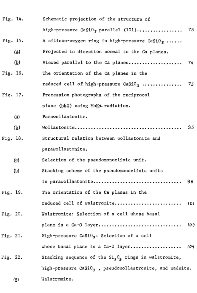
Fig. 15. A silicon-oxygen ring in high-pressure CaSiO3 . . . . (a) Projected in direction normal to the Ca planes.
U2) Viewed parallel to the Ca planes... 74 Fig. 16. The orientation of the Ca planes in the
reduced cell of high-pressure CaSiO3 . . . 75
Fig. 17. Precession photographs of the reciprocal
plane
(hkQ)
using MoKSL radiation.
(a) Parawollastonite.
(b) Wollastonite... 35 Fig. 18. Structural relation between wollastonite and
parawollastonite.
(a)
Selection of the pseudomonoclinic unit.(b)
Stacking scheme of the pseudomonoclinic unitsin parawollastonite... 96 Fig. 19. The orientation of the Ca planes in the
reduced cell of walstromite... 10) Fig. 20. Walstromite: Selection of a cell whose basal
plane is a Ca-0 layer...103 Fig. 21. High-pressure CaSi03: Selection of a cell
whose basal plane is a Ca-0 layer... 104 Fig. 22. Stacking sequence of the Si.09 rings in walstromite,
high-pressure CaSi03 , pseudowollastronite, and wadeite.
(b) High-pressure CaSiO3.
(c) Pseudowallostonite assumed anlogous with SrGe03 *
)
Wadeite... 107 Fig. 23. A schematic picture of the structure of wollastoniteas well as parawollastonite, viewed along the
direction of the chains... 110 Fig. 24. A schematic picture of the structure of
high-pressure CaSiO3viewed along a direction
parallel to the Ca layers... III Fig. 25. Two pseudomonoclinic units of wollastonite
displaced in respect to each other by the amount
b/2 parallel the plane (001)... 112
Fig. 26. A possible mechanism for constructing Si30, rings out of Si309 chains.
(a) S130, chain in wollastonite and parawollastonite.
(b)
Si3O3 ring in high-pressure CaSiO3 . . .1/4
Fig. 27. An idealized structure of wollastonite projected perpendicular to the Ca network. (a) The SiO4 tetrhedra form chains
Table 1- Cell dimension of parawollastonite... 20
Table 2. Mamedov and Belov's coordinates for wollastonite based upon a monoclinic cell... 23
Table 3. Some observed structure factors with the corresponding F's based on Mamedov and Belov's coordinates and the final refined Fcal's, for parawollastonite... 24
Table 4. Positional coordinates for parawollastonite... 28
Table 5. Interatomic distances in parawollastonite... 29
Table 6. Bond Angles between atoms in parawollastonite... 30
Table 7. Anistropic temperature coefficients for parawollastonite... 33
Table 8. Thermal parameters for parawollastonite... 34
Table 9. Observed and computed structure factors of parawollastonite... 46
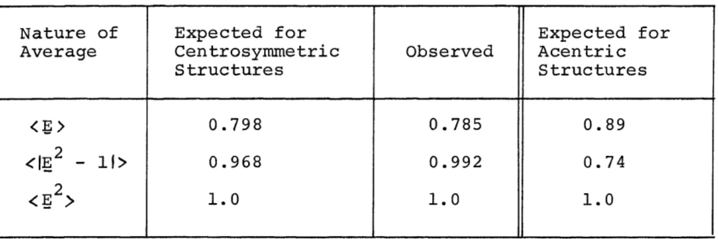
Table 10. Theoretical and observed statistical averages of normalized structure factors for high-pressure CaSiO3 . . .
58
Table 11. Symmetry and cell data for the high-pressure polymorph of CaSiO3 . . . 59
Table 12 . Summary of the sixteen models obtained by application of R.E. Long's sign determination program for high-pressure CaSiO3 . . . 64
Table 13 . Atomic coordinates for the high-pressure polymorph of CaSiO3 . . . 69
Table Table Table Table Table 14. 15. 16. 17. 18.
Interatomic distances for high-pressure CaSiO... Bond angles for high-pressure CaSiO3 .''''**.
Anisotropic temperature coefficients for
high-pressure CaSiO3 . . . .... Thermal parameters for high-pressure CaSiO3 . . . .. Observed and calculated structure factors of
high-pressure CaSiO.. ...
Comparison of the y coordinate of atoms in parawollastonite with the
position (2n+1)/8... Cell constants of walstromite and
high-pressure CaSiO3 . . . ... Page Table 19. Table 20. 76
78
81
82
83
97
100
GENERAL BACKGROUND
The silicates form the most abundant mineral group in nature, about ninety per cent of the earth's mantle is composed of silicates. In addition, the silicates play an ever increasing role in industrial products such as glass, cement, porcelain, bricks and other innumerable synthetic products. Naturally many attempts were made to establish a systematic of this important group of minerals. The first classification was based on chemical consider-ations, and the silicates were interpreted as salts of the various silicic acids. This preliminary classification was abandoned when the first struc-tural knowledge was obtained by x-ray diffraction and replaced by a system-atic based upon the arrangement of the S104 tetrahedra. In this respect pioneering work was performed by Machatschki (1928) and especially by Bragg
(1930) whose systematic of silicates remained virtually unchallenged until today. Bragg divided the silicates into five classes:
I Separate SiO+ tetrahedra.
II Separate silicon-oxygen complexes. III Silicon-oxygen chains.
IV Silicon-oxygen sheets. V Framework silicates.
Another classification frequently used is the one established by Strunz; for example published in Strunz (1966):
I Nesosilicates (separate SiOg tetrahedra) II Sorosilicates (double tetrahedra).
III Cyclosilicates (ring-silicates). IV Ionosilicates (chain-silicates).
11.
V Phyllosilicates (sheet-silicates). VI Tectosilicates (framework silicates).
The present investigation represents a study of the various phases of calcium metasilicate, CaSiO3. As the chemical formula indicates by its silicon-oxygen ratio, the calcium metasilicates belong either to the ring-silicates or to
the chain-silicates or include both structural types. These two structural types are the only ones where the silicon-oxygen ratio is 1:3 or multiples of it. A detailed systematic of silicates by Liebau (1962) was found very useful to define a rough outline of the problems to be considered in this investi-gation. Liebau gives an excellent survey about the hitherto known crystals chemistry of chain-silicates and ring-silicates. Hence a thorough study of the calcium metasilicates ought to encompass following criteria:
I Examination of the nature of the SiO4 assemblage.
a Silicon-oxygen chains. Determination of the chain type. As of now chains with a repeating unit of 2, 3, 4, 5, 7, and 9 tetrahedra are known, other repeating units are predicted but have not yet been found in silicates. b Silicon-oxygen rings. Determination of the ring type.
Rings composed of 3, 4, and 6 tetrahedra are known to exist.
II Examination of the arrangement of the calcium-oxygen polyhedra. Recent studies of silicates have shown that the size of the large cations as well as the way they are coordinated and linked together by oxygens have a strong influence upon the arrangement of the SiO4 tetrahedra.
SCOPE OF THE THESIS
The mineral wollastonite, the most prominant member of the calcium metasilicates, was discovered 150 years ago. It is a well known
constituent in metamorphosed limestone and is also found in contact altered calcerous sediments. Based on morphological studies, wollastonite was originally classified as a pyroxene. With the introduction of x-ray dif-fraction technique as a powerful tool to identify crystals, many pyroxenes were investigated and their structures worked out. The main characteristic
was found to be the arrangement of the SiO tetrahedra in the form of infinite chains with a repeating unit of two tetrahedra. When wollastonite was in-vestigated with x-rays by Warren (1931), it became evident that this mineral probably had a structure different from the one found in pyroxenes such as
diopside. Wollastonite and all the other modifications of calcium metasilicate were therefore classed as pyroxene-like minerals and were assigned to a related
structural group, namely the pyroxenoids. Many years later Mamedov and Belov (1956) determined the crystal structure of wollastonite and found silicon-oxygen chains to be present which have a repeating unit of three tetrahedra. The different length of the chain repeat is henceforth considered to be the most important criterion to differentiate pyroxenes, which have a repeat of two tetrahedra, from pyroxenoids, which have a repeat of three or more tetra-hedra.
The occurrence of several modifications of calcium metasilicate was already known at the end of the last century. However, only one phase, namely wollastonite was given a careful x-ray investigation. Mamedov and
13.
Belov determined the crystal structure of triclinic wollastonite and suggested a proposal for the monoclinic variety, called parawollastonite. Another modification was discovered by Bourgeois (1882). The symmetry of this compound was determined by D0lter (1886) by optical means, and he reported it to be either hexagonal or orthorhombic. Later this phase was named pseudowollastonite by Allen, White, and Wright (1906), and several attempts were made to solve its structure. Jeffrey and Heller (1953) made a preliminary x-ray investigation but could not proceed with a structure determination because of bad crystalline material. Hilmer (1963) circum-vented this difficulty by solving the structure of strontium germanate, which is considered to be analogous with pseudowollastonite.
This brief outline shows that the knowledge of calcium metasilicates is a rather limited one. Of the three minerals only triclinic wollastonite has been studied in detail. Since this phase has been classed as a mineral
belonging to the pyroxenoid group, it is natural to ask whether the other modifications of calcium metasilicate such as parawollastonite, pseudo-wollastonite, and perhaps other high-temperature, high-pressure phases of
CaSi03 adhere to the same chain structure type. As a consequence the investigation of structural features in common with the various phases of CaSiO3 as well as those which are different in each structure will be of
great interest. This in turn lays the ground for a study of possible transformation mechanisms between these structures.
In view of these questions it was considered desirable to determine and refine the crystal structures of parawollastonite and a high-pressure phase of CaSi03. The latter compound was chosen because single crystals
of pseudowollastonite suitable for crystal structure analysis were not available until now. Moreover the powder pattern of this compound shows a remarkable resemblance with the one obtained from pseudowollastonite, thus promising to reveal some strucutral relation with pseudowollastonite. The crystallographic examination was undertaken according to the following plan.
The first chapter deals with parawollastonite. A careful structure analysis essentially confirms the proposal by Mamedov and Belov. The dis-pute over the correct space group, P21/a or P2, , for parawollastonite is
solved by comparing the agreement of the computed structure factors with the observed ones for both space groups. The considerably better agreement obtained for P21/a warrants the assumption that the centrosymmetric space group is the correct one for parawollastonite. Previous investigators reported so called non-space group extinctions. This problem is studied and explained in terms of a distinct substructure. This substructure also gives the answer to the presence of pseudosymmetry elements in parawollastonite. The last section in this chapter is concerned with the disorder frequently observed in wollastonite, as well as in parawollastonite. An attempt is made to explain this disorder in terms of stacking faults between neighboring cells and intergrowth of wollastonite and parawollastonite.
The second chapter presents the structure determination and refinement of a high-pressure, high-temperature phase of calcium metasilicate. It was the deliberate aim not to use a substitute analogous compound in order to establish the actual structure of such a phase in the CaSiO3 system. The most surprising result of this structure determination was the discovery of
15.
the silicon-oxygen tetrahedra forming three-member rings. The calcium-oxygen polyhedra form imperfect layers. In the discussion of this structure it is shown that it is possible to conceive of an idealized structure of high-pressure CaSiO. with hexagonal, octahedral layers. The idealized
struc-ture can be used to describe the relation to the proposed strucstruc-ture of pseudo-wollastonite.
The third and last chapter is dedicated to comparative studies. The first section in this chapter relates the structures of wollastonite and parawollastonite. It confirms Ito's (1950) proposal that the different ar-rangement of pseudomonoclinic units determines either structure. Of great interest, however, is a comparison of the chain structures of the two mod-ifications of wollastonite with the ring structure of this high-pressure phase of CaSiO3 . Although, at the first glance, one is inclined not to find any
similarities, a number of surprising, common strucutral features are found in both structures. Hence it seems quite possible that wollastonite transforms
into this new phase of CaSiO, under the proper environmental conditions. A possible transformation mechanism is proposed in this chapter. The changes required by this transition are such that they are probably reversible, since they do not alter the basic layer-like arrangement of the calcium-oxygen poly-hedra. There is some credibility to this assumption since a similar inversion, namely of wollastonite to pseudowollostanite, is known to be fairly easily reversible. In addition, a comparison of high-pressure CaSiO.,
pseudo-wollastonite and walstromite with each other reveals that these three compounds can be considered as members of the same polymorphic set. The third chapter concludes with a structural classification. The various modifications of
calcium metasilicate are examined in light of several criterions suggested by Prewitt and Peacor (1964) for the pyroxenes and pyroxenoids as well as those proposed by Dornberger-Schiff (1962) for pseudowollastonite.
17.
CHAPTER I
PARAWOLLASTONITE
Introduction
In the year 1818 the mineral wollastonite was first identified by Monticelli (1825) in volcanic bombs from Mt. Somma, Italy. Early
mor-phological studies suggested that wollastonite has monoclinic symmetry and belongs to the pyroxene group. Eakle (1917), however, observed triclinic symmetry on some wollastonite crystals. This in turn raised the question whether wollastonite is monoclinic or triclinc. This ambiguity was solved by Warren (1931) who clearly found triclinic symmetry for wollastonite in an x-ray investigation using oscillation and rotation photographs. In addition, Warren observed that even layer lines show monoclinic symmetry. This made him conclude that a monoclinic variety could be obtained where successive cells are shifted by the amount
±
b/2. Using these results Peacock (1935)established the existance of two phases of low temperature calcium meta-silicate: triclinic wollastonite and monoclinic parawollastonite.
In an attempt to solve the structure of the monoclinic variety, Barnik (1936) proposed Si3 09 rings as the main structural feature for parawollastonite. He also reported the systematic absence of hkl reflections of the type 2h + k
= 4n + 2, which is not required by space group P21/a. His proposal was strongly criticized, mainly because the ring structure could not explain the fibrous character of the crystals.
The similarity of x-ray diffraction patterns from wollastonite with those of the Madrell salt (NaPO3)x sodium polyarsenate (NaAsO,)x, and
chemical considerations, Thilo and Plaetschke (1949) assumed a chain struc-ture for sodium polyarsenate and the Madrell salt. Dornberger-Schiff, Liebau, and Thilo (1955) were able to determine the structure of sodium polyarsenate. These authors confirmed the chain character and hence ruled out the ring arrangement for similar compounds such as wollastonite. Further
evidence for a chain structure in wollastonite was presented by the structure determination of xonotlite by Mamedov and Belov (1955) and of pectolite by Buerger (1956).
With the aid of direct methods Mamedov and Belov (1956) were able to determine the structure of wollastonite in which Si30. chains parallel to the
b axis were found to be a basic structural feature. They used two-dimensional film data and indexed only the strong reflections of layers with k even. Their indexing was based on both a triclinic cell, f1, and on a double monoclinic cell P2j/a. The 204 strong reflections satisfied the condition 2h + k = 4n; this
characterization bears a kind of complementary relation to Barnik's systematic absence 2h + k = 4n + 2, but is not equivalent to it. The Russian authors reported an R value of 24% for the strong h01 reflections.
Tolliday (1958) proposed a structure for monoclinic parawollastonite. She started the refinement using the centric space group P21/g. This attempt
was not satisfactory, so P21/g was replaced by the noncentric space group P21.
After making this change, Tolliday reported that the refinement was progress-ing well. Unfortunately no coordinates, structure factors, or R values were published so that the validity of her findings can be appraised. In the view of this unsatisfactory state of affairs, a reinvestigation of the structure of parawollastonite appeared desirable.
19.
Material and Experimental Data
A specimen of parawollastonite crystals from Crestmore, California, was kindly provided by Dr. Charles T. Prewitt. The crystal used in the present investigation was carefully examined, and the quality of the dif-fraction pattern was sufficient to proceed with the intensity determination.
The space group P21/a was determined from precession photographs, which
is consistent with Barnik's (1936) result. In addition to the extinctions caused by the two fold screw axis and the glide plane, the reflections hkl of the type 2h + k = 4n + 2, were considered to be absent until now, due to some specialised locations of the atoms in the structure. This unusual phenomenon seemed to be worth checking. Although the results of film data were incon-clusive on this matter a very weak diffracted x-ray beam, especially in upper levels of the index k, could be detected with a single-crystal diffractometer using advanced counter methods. Therefore these reflections were classified as present, but very weak, and hence were included in the intensity measure-ments.
Precise lattice constants were obtained by evaluating data from
back-reflection Weissenberg films. These data were refined by least-squares methods. The dimensions for the cell of parawollastonite are given in Tible 1, which shows that the new values are in good agreement with results published by Barnik
(1936), and by Tolliday (1958).
r
-Table 1. Cell Dimensions of Parawollastonite. Barnik (1936) Tolliday (1958) 15.33 A 15.417 + 0.004 A 7.28 7.321 ± 0.002 7.07 7.066 ± 0.002 95* 24' 30" 950 24' + 3' Present Work 15.426 ± 0.004 A 7.320 t 0.003 7.066 ± 0.003 95*24' 15" ± 50" Parameter
21.
Nickel-filtered Cukd, radiation was used to record 1290 reflections with an equi-inclination single-crystal diffractometer. In order to obtain accurate experimental data, a proportional counter was employed in connec-tion with pulse-height discriminaconnec-tion. Weissenberg photographs using the same geometry as the diffractometer showed that white radiation streaks of strong reflections extend to the next lattice point on the same lattice line. For this reason, the recorded intensity of a reflection with a strong,
neighboring reflection of lower sind on the same lattice line, was usually recorded too high. Hence the integrated intensities had to be corrected for this residual white radiation which could not be eliminated by pulse-height discrimination and the Ni filter. The method applied is similar to the procedure outlined by Larson (1965), a detailed description of it is given by Trojer (1966). The improved data were corrected for Lorentz and polar-ization factors as well as for absorption. The observed structure factors are listed in Table 9.
Refinement
The coordinates published by Mamedov and Belov (1956) for wollastonite, as referred to a double monoclinic cell, were tested with the present data and a preliminary set of structure factors calculated. With the proper scale factor and an overall isotropic temperature factor of B = 0.6 A , the dis-crepancy between the computed and observed structure factors, also called R,
had the rather large value of 52%.Mamedov and Belov's atomic parameters are presented in Table 2. With the exception of their Si I, Si I', 0 IV, and
IV', all positions listed in this table have y coordinates of (2n + 1)/8; these coordinates require absences of hkl reflections with 2h + k = 4n + 2. Tolliday (1958) reported having observed this extinction rule. Table 3 gives a representative sample of observed and computed structure factors for those reflections. This table shows that the non-space group extinctions are almost obeyed by Mamedov and Belov's model for wollastonite. Actually, as observed in the present investigation, the structure amplitudes of the reflections corresponding to this extinction rule, although small, are not zero.
Tolliday's view that parawollastonite should be refined in the noncentric space group P21 was tried without success. The refinement came to a halt at an R value of 16% and gave no indication of further improvement. Accordingly space group P21/a was retained and several cycles of least-squares refinement were carried out with the SFLSQ 3 program written by C.T. Prewitt and recorded by Onken (1964). The scattering curves used in the refinement program were adjusted for anomalous dispersion. For Cukctradiation the following correction terms were used for the metal atoms: Ca: Af' = 0.3, &f"= 1.4, and Si: f'= 0.2,
23.
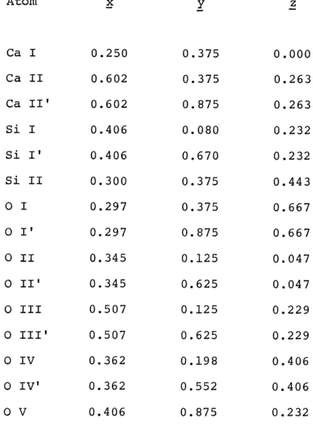
Table 2. Mamedov and Belov's Coordinates for Wollastonite
Based upon a Monoclinic Cell.
Atom x y z Ca I 0.250 0.375 0.000 Ca II 0.602 0.375 0.263 Ca II' 0.602 0.875 0.263 Si I 0.406 0.080 0.232 Si I' 0.406 0.670 0.232 Si II 0.300 0.375 0.443 0 I 0.297 0.375 0.667
o
I' 0.297 0.875 0.667 0 II 0.345 0.125 0.047o
II' 0.345 0.625 0.047o
III 0.507 0.125 0.229 0 III' 0.507 0.625 0.2290 IV
0.362
0.198
0.406
0 IV'
0.362
0.552
0.406
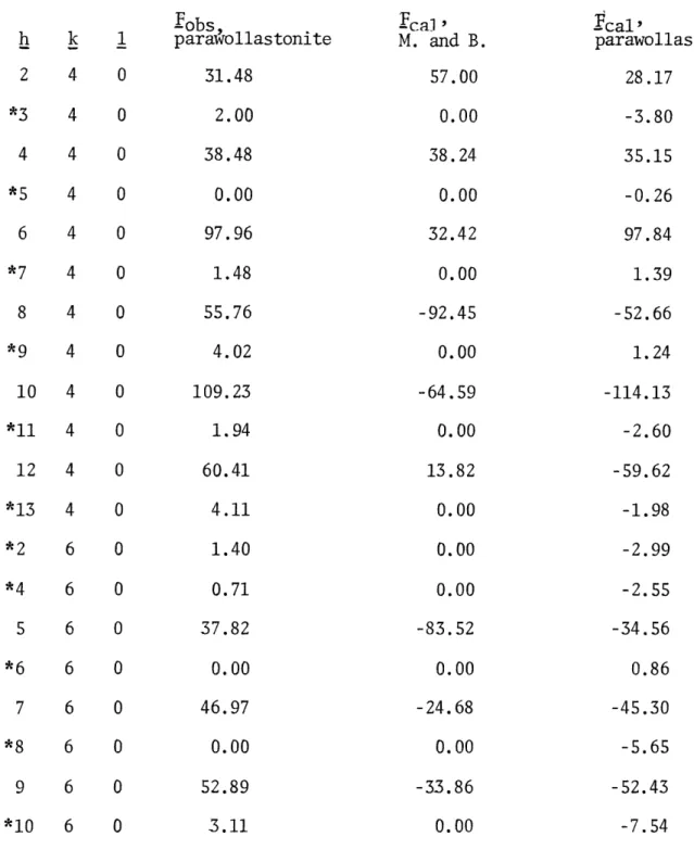
0 V 0.406 0.875 0.232Table 3. Some Observed Structure Factors with the Corresponding F's
based on Mamedov and Belov's Coordinates and the Final Refined
Ecal's for Parawollastonite. Indices with an Asterisk refer to
"absences" in hkl with 2h +
k
= 4n + 2. All Structure Factorsare in Electron Units.
Fobs
h
k
1
parawollastonite
Ica] '
M. and B.
rcal'
parawollastonite
2
4
0
*3
4
0
4
4
0
*5
4
0
6
4
0
*7
4
0
8
4
0
*9
4
0
10
4
0
*11
4
0
12
4
0
*13
4
0
*2
6
0
*4
6
0
5
6
0
*6
6
0
7
6
0
*8
6
0
9
6
0
*10
6
0
31.48
2.00
38.48
57.00
0.00
38.24
0.00
0.00
97.96
1.48
55.76
4.02
109.23
1.94
60.41
32.42
0.00
-92.45
0.00
-64.59
0.00
13.82
4.11
1.40
0.71
0.00
0.00
0.00
-83.52
37.82
0.00
46.97
0.00
52.89
0.00
-24.68
0.00
-33.86
28.17
-3.80
35.15
-0.26
97.84
1.39
-52.66
1.24
-114.13
-2.60
-59.62
-1.98
-2.99
-2.55
-34.56
0.86
-45.30
-5.65
-52.43
3.11
0.00
-7.54
25.
Table 3. Continued.
.obs'
h
k
1
parawollastonite
43.59
43.24
2.02
1.67
24.20
60.81
0.60
3.02
25.60
7.03
1.40
1.25
31.19
25.85
2.21
0.00
42.36
98.31
4.82
3.27
-cal'
M. and
B.
-41.01
41.01
0.18
0.02
-44.97
76.14
0.08
-0.18
12.49
-32.25
0.14
0.04
74.60
-20.39
-0.10
0.11
-81.02
-57.32
-0.08
-0.06
-cal'parawollastonite
-36.55
-36.55
0.81
3.11
-23.13
60.93
-5.47
5.84
-25.65
-7.94
2.13
5.38
31.80
21.41
-3.70
2.10
-39.91
-99.14
2.37
3.48
Af" = 0.4. Employing an equal weighting scheme and allowing all parameters to vary, the best R value with individual, isotropic temperature factors for
each atom was 8.4%.
At this stage of the investigation it became evident that the shifts performed by the least-squares refinement showed no tendency to locate atoms on positions responsible for the non-space group extinctions. In order to obtain an excellent agreement between observed and computed data with a least-squares refinement a proper weighting scheme is necessary, thus a weighting factor w = 'Fobs| was attributed to each reflection. This weighting procedure is described in detail by de Vries (1965). With introduction of anisotropic thermal parameters the final R values were obtained: R (unweighted) = 6.6%, R (weighted) = 4.9%. In contrast to Mamedov and Belov's proposal this refined model of the structure of parawollastonite does not demand absences of hkl
reflections with 2h + k = 4n + 2. A comparison of these observed structure factors with the corresponding final ones in Table 3 shows a fairly good agreement considering the fact that the counting statistics are very poor for such weak intensities.
27.
Discussion of the Structure
The low residual value of 6.6%, compared with the R = 16% for the noncentric space group P2,, confirms the centric space group P2./: as the correct one for parawollastonite. All the atoms in this structure occupy the general position 4e. The final coordinates are listed in Table 4. Table 5 gives the interatomic distances and Table 6 the bond angles between atoms. A projection of the structure of parawollastonite along 2 is illustrated in Fig. 1.
The Ca atoms are surrounded by distorted oxygen octahedra which form three slabs within the cell parallel b. A slab consists of three rows of Ca octahedra sharing edges with each other. The center row built up by Ca(l) and its surrounding oxygens has an average Ca(l)-0 distance of 2.368
*
A. The two rows, one composed by Ca(2), the other by Ca(3), on either side of the center row have octahedra with a slightly larger, average Ca-0 distance of 2.402 A. This average distance is the same for Ca(2) and Ca(3). Ca(l) is linked to an additional seventh oxygen, 0(9), at a rather large distance of
0
2.895 A. Similar Ca-0 distances are reported by Peacor and Buerger (1962) 0
for bustamite, such as Ca,-0, = 2.899 A and Ca2 -0. = 2.891 A.
The Si atoms are tetrahedrally coordinated. The deviations from the ideal tetrahedral angle = 109*28' are considerable, the values varying between 96010' and 129030'. Prewitt and Buerger (1963) reported three nonequivalent Si-0-Si angles in wollastonite as well as in bustamite. The corresponding angles for parawollastonite lie between those for wollastonite and bustamite:
bustamite 1610, 1350, 137* parawollastonite 1520, 1350, 1370 wollastonite 1490, 139*, 137*
Table 4. Positional Coordinate for Parawollastonite
Atom 6()y (y)
z Ca(l) 0.2482 0.0001 0.3758 0.0004 0.9712 0.0002 Ca(2) 0.4011 0.0001 0.6265 0.0006 0.7397 0.0002 Ca(3) 0.3987 0.0001 0.1209 0.0006 0.7364 0.0002 Si(l) 0.4076 0.0001 0.0907 0.0003 0.2313 0.0003 Si(2) 0.4075 0.0001 0.6598 0.0003 0.2313 0.0003 Si(3) 0.3016 0.0001 0.3761 0.0004 0.4432 0.0002 0(1) 0.3000 0.0003 0.3747 0.0013 0.6685 0.0006 0(2) 0.2156 0.0003 0.3759 0.0013 0.3031 0.0007 0(3) 0.3490 0.0004 0.1397 0.0014 0.0328 0.0007 0(4) 0.3473 0.0003 0.6157 0.0015 0.0348 0.0007 0(5) 0.5086 0.0003 0.1226 0.0020 0.2388 0.0007 0(6) 0.5078 0.0003 0.6176 0.0019 0.2347 0.0007 0(7) 0.3642 0.0004 0.1962 0.0007 0.4060 0.0007 0(8) 0.3633 0.0004 0.5533 0.0008 0.4067 0.0008 0(9) 0.3906 0.0003 0.8755 0.0010 0.2767 0.0006
29.,
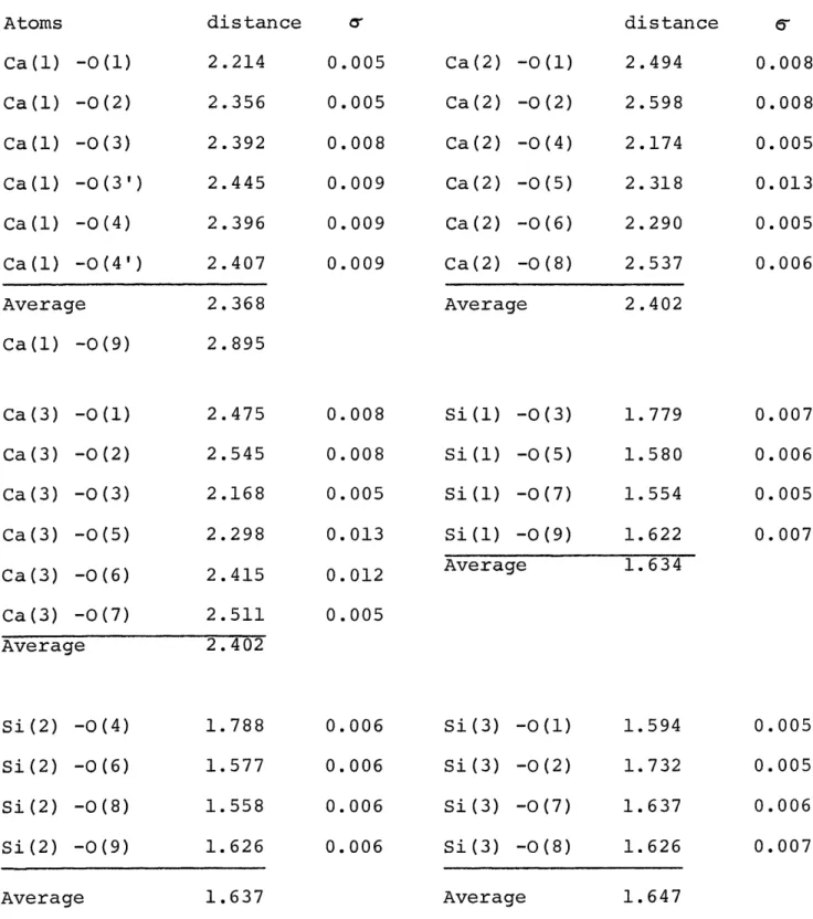
Table 5. Interatomic Distances in Parawollastonite. 0(3') is
Equivalent by Symmetry to 0(3), and 0(4') to 0(4).
Atoms Ca(1) Ca(l) Ca(l) Ca(1) Ca (1) Ca(1) -0(1) -0(2) -0(3) -0(3') -0(4) -0(4') Average Ca(1) -0(9) distance 2.214 2.356 2.392 2.445 2.396 2.407 2.368 2.895 00 0.005 0.005 0.008 0.009 0.009 0.009 Ca(2) Ca(2) Ca (2) Ca (2) Ca(2) Ca(2) -0(1) -0(2) -0(4) -0(5) -0(6) -0(8) Average distance 2.494 2.598 2.174 2.318 2.290 2.537 2.402 Ca (3) Ca (3) Ca(3) Ca(3) Ca(3) Ca(3) -0(1) -0(2) -0(3) -0(5) -0(6) -0(7) 2.475 2.545 2.168 2.298 2.415 2.511 Average 2.402 Si(2) -0(4) 1.788 Si(2) -0(6) 1.577 Si(2) -0(8) 1.558 Si(2) -0(9) 1.626 Average 1.637 0.008 0.008 0.005 0.013 0.012 0.005 0.006 0.006 0.006 0.006 Si(1) -0(3) Si(l) -0(5) Si(1) -0(7) Si(1) -0(9) Average Si(3) -0(1) Si(3) -0(2) Si(3) -0(7) Si(3) -0(8) Average 6-0.008 0.008
0.005
0.013 0.005 0.006 1.779 1.580 1.554 1.622 0.007 0.006 0.005 0.007 1.634 1.594 1.732 1.637 1.626 0.005 0.005 0.006 0.007 1.647Table 6. Bond Angles Between Atoms in Parawollastonite. 0(3') is
Equivalent by Symmetry to OC3), and
OC4')
to OC4)
Atoms
0(1) -Ca(1) -0(2)0(3)-Ca(l)-0(4)
0(3)-Ca(1)-0(4)
0(3')-Ca(l)-0(4)
0(3)-Ca(1)-0(4')
0(3)-Ca(1)
-0C2)
0(3')-Ca(1)-0(2)
0(4)-Ca(1)-0(2)
0(4')-Ca(1)-0(2)
0(3) -Ca(3)
0(1) -Ca(3)
-0(2)
0(1)-Ca(3)-0(6)
0(2)-Ca(3)-0(5)
0(5) -Ca (3)-0(6)0(1)-Ca(3)-0(3)
0(2)-Ca(3)-0(3) 0(5) -Ca(3) -0(3) 0 (6) -Ca (3) -0 (3)angle
1710,12' 93*15'80048'
80001' 104021184*07'
86033?83440'
86036? 143020? 93034?78*47'
84033? 103003? 88034?88*
13' 97057? 91025? Atoms 0(4)-Ca(2)-0(8) 0(1) -Ca(2) -0(2) 0(1)-Ca(2)-0(6)0(2) -Ca(2)
-0(5)
0 (5) -Ca (2) -0
C6)
0(1)
-Ca(2)
-0(4)
0(2) -Ca(2)-0(4)
0(5)
-Ca(2)-0(4)
0(6)-Ca(2)-0(4)
0(3) -Si(1) -0(5)
0(3)-Si(l)-0(7)
0(5)-Si(l)-0(7)
0(3)
-Si(1) -0(9)
0 (5) -Si(1) -0 (9)
0(7) -Si(1)
-0(9)
angle
141051? 92027? 80047? 82059?103*37'
88053?
86016' 98006? 94017? 125000? 108030? 104025? 105031? 106006? 105059?31.
Table 6. Continued.
Atoms
0C2)-SiC3)-0(7)
0(2)-Si(3)-0(8)
0(7)
-Si C3)-0(8)
0(2)-Si(3)-0(l)
0(7)-Si(3)-0(1)
0(8)-Si(3)-0(1)
angle
112417'
112013'107011'
129030' 96039' 96010'Atoms
0(4)
-Si(2) -0(6)
0(4)
-Si
(2)-0(6)
0(6)-SiC2)-0(8)
0(4)-SiC2)-0(9)
0(6)
-SiC2) -0(9)
0(8)-Si(2)-0(9)
Si(1)-0(9)-Si(2)
Si(1)-0(7)-Si(3)
Si(2)-0(8)-Si(3)
angle
124007'
108034'104*11'
104*08'
109000?
105*35'
151048?
135025?
136032'
Fig. 1.
Projection of the structure of parawollastonite along
c.
The double circles are Ca atoms, the full circles
0(6)
(2)
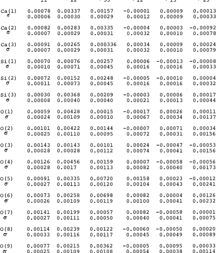
Table 7. Anisotropic Temperature Coefficients for Parawollastonite. /333 /313 Ca(1) 0.00078 0.00337 0.00157 6 0.00006 0.00030 0.00029 Ca(2) 0.00082 0.00283 0.00335 e 0.00007 0.00029 0.00031 Ca(3) 0.00091 0.00265 0.000336 ( 0.00007 0.00029 0.00031 Si(1) 0.00070 0.00076 0.00257 a 0.00010 0.00071 0.00045 Si(2) 0.00072 0.00152 0.00248 a 0.00011 0.00073 0.00045 Si(3) 0.00030 0.00368 0.00209 a 0.00008 0.00040 0.00040 0(1) 0.00059 0.00428 0.00015 0 0.00024 0.00109 0.00010 0(2) 0.00101 0.00422 0.00144 6 0.00025 0.00110 0.00095 0(3) 0.00143 0.00143 0.00101 0.00028 0.00028 0.00112 0(4) 0.00126 0.00456 0.00159 a 0.00028 0.0017 0.00113 -0.00001 0.00012 -0.00004 0.00032 0.00009 0.00013 0.00009 0.00033 0.00003 -0.00092 0.00010 0.00078 0.00034 0.00009 0.00024 0.00032 0.00010 0.00079 0.00006 -0.00013 -0.00008 0.00016 0.00016 0.00033 -0.00005 0.00016 -0.00003 0.00021 -0.00017 0.00067 -0.00007 0.00072 -0.00010 0.00016 0.00004 0.00032 0.00006 0.00017 0.00013 0.00044 0.00026 0.00011 0.00034 0.00137 0.00071 0.00034 0.00031 0.00156 0.00024 -0.00047 0.00074 0.00041 0.00007 -0.00058 0.00082 0.00040 -0.00053 0.00156 -0.00056 0.00173 0.00091 0.00335 0.00720 0.00027 0.00113 0.00120 0.00073 0.00258 0.00698 0.00026 0.00109 0.00119 0.00141 0.00199 0.00057 0.00027 0.00111 0.00050 0.00114 0.00239 0.00122 0.00033 0.00116 0.00117 0.00077 0.00215 0.00362 0.00025 0.00109 0.00108 0.00158 0.00023 -0.00012 0.00104 0.00043 0.00241 0.00082 0.00004 0.00126 0.00100 0.00041 0.00232 0.00082 -0.00058 0.00040 0.00041 -0.00060 0.00045 -0.00005 0.00054 -0.00050 0.00049 0.00001 0.00075 0.00020 0.00089 0.00095 0.00033 0.00038 0.00114 Atom /23 0(5) 0(6)
O')
0(7) 0(8) 0(9)0'
34.
Table 8, Thermal Parameters for Parawollastonite. The dimensions are: q
0 inA, B. and B in A.0 B Atom Ca(1) 0.097
a
0.004
Ca(2) 0.102 T' 0.004 Ca(3) 0.1066'
0.004
Si(1) 0.094 T' 0.006 Si(2) 0.095 T' 0.006 Si(3) 0.060 y 0.008 0(1) 0.084 6 0.017 0(2) 0.110 07 0.103 0(3) 0.133 a 0.012 0(4) 0.126 U 0.013 0(5) 0.120 0' 0.016 0(6) 0.101 0- 0.017 0(7) 0.134 (Y 0.012 0(8) 0.121 0' 0.015 0(9) 0.086 lo' 0.011 B 0.75 0.06 0.81 0.06 0.89 0.07 0.70 0.09 0.72 0.09 0.28 0.08 0.55 0.23 0.96 0.23 1.40 0.26 .25 .25 1.14 0.31 0.81 0.28 1.41 0.25 1.16 0.29 0.58 0.15 Equivalent isotropic B 0.096 0.72 0.004 0.06 0.082 0.52 0.006 0.08 0.083 0.54 0.006 0.07 0.045 0.16 0.021 0.15 0.064 0.33 0.015 0.16 0.100 0.79 0.005 0.09 0.108 0.92 0.014 0.23 0.107 0.90 0.014 0.23 0.104 0.86 0.016 0.26 0.111 0.98 0.014 0.25 0.073 0.42 0.020 0.23 0.072 0.41 0.021 0.24 0.071 0.39 0.020 0.23 0.078 0.48 0.019 0.24 0.075 0.45 0.018 0.22 0.063 0.31 0.006 0.06 0.095 0.71 0.005 0.08 0.092 0.67 0.005 0.07 0.078 0.48 0.006 0.08 0.077 0.47 0.007 0.08 0.073 0.42 0.007 0.08 0.018 0.02 0.072 0.20 0.058 0.26 0.020 0.18 0.048 0.19 0.028 0.22 0.060 0.28 0.023 0.21 0.136 1.45 0.011 0.23 0.134 1.42 0.011 0.24 0.035 0.10 0.036 0.10 0.042 0.14 0.038 0.25 0.104 0.85 0.010 0.16 0.63 0.03 0.71 0.04 0.70 0.04 0.41 0.06 0.51 0.07 0.49 0.05 0.49 0.12 0.71 0.12 0.82 0.14 0.79 0.14 1.00 0.15 0.88 0.15 0.63 0.13 0.59 0.15 0.63 0.10The interatomic distances within the SiO. tetrahedra can be separated into two groups: (a) oxygens coordinated by 1 Si and 3 Ca, with an average Si-O distance of 1.723 A; (b) oxygens coordinated 1 Si and 2 Ca or by Si and 1 Ca, with an average Si-O distance of 1.576 A. It can be seen that the Si-O
distances are considerably larger if the oxygen atoms are coordinated by three Ca. A similar classification was found for wollastonite by Prewitt and
Buerger (1963).
The anisotropic temperature coefficients for parawollastonite are found in Table 7. The orientations of the thermal vibration, ellipsoids expressed
by the /3, /3 /32, values, are not well refined. In order to improve these
parameters a largernumber of observed reflections would be necessary. The thermal parameters are listed in Table 8. The q. 's (i = 1 to 3) are the three principal axes of the vibration ellipsoid. A temperature factor B corresponds
to each principal axis. The last column in Table 8 lists the average B computed by B = (B + Bz + B,)/3 which is substantially the usual isotropic temperature factor. The values for parawollastonite are comparable with those for wollastonite published by Buerger and Prewitt (1961).
35.b
Pseudosymmetry and Substructure
A close examination of the pseudomonoclinic unit, Fig. 2a reveals that, in addition to the inversion centers which are a remnant of the symmetry of triclinic wollastonite, a set of pseudosymmetry elements is also present. Figure 2b illustrates the following symmetry elements in this pseudomonoclinic unit: inversion centers, pseudomirror planes, and a pseudo 21 axis. There are also pseudoinversion centers which are generated by the combination of a true inversion center and a psuedomirror plane. All these pseudosymmetry elements mentioned above are only approximately obeyed by the atomic configuration. Figure 2c shows that certain symmetry elements become pseudosymmetry elements, and vice versa, when those units are stacked together to form the parawollastonite structure. The pseudo 21 axis changes to a true 21 axis. The combination of the true 21 axis with a true inversion center gives rise to a glide plane. The
former true centers of symmetry on the pseudo 21 axis become pseudoinversion centers.
This pseudosymmetry suggests that parawollastonite might have a sub-structure. If small changes in the coordinates of some atoms are introduced in the actual parawollastonite structure an idealized structure results which has a distinct substructure. The necessary shifts do not exceed 0.08 of the x, y, or z coordinates. As seen from Fig. 3, this idealized structure is
remarkably close to the actual structure of parawollastonite. Figure 3a
shows that the Ca and Si atoms each conform to a substructure which consists of a simple lattice array. Both sets of atoms have very similar x and y
coordinates. In respect to the Ca network, the Si atoms are shifted up along the c direction by the amount z = k. With the exception of 0(7), 0(8), and
Fig. 2.
Symmetry in parawollastonite. The pseudomonoclinic
units are shaded. Double circles are Ca atoms. Small
solid circles are real centers of symmetry, small open
circles are pseudocenters. The pseudomirrors and psuedo
screw axis are represented by thin double lines.
(a)
Pseudomonoclinic unit.
(b)
Symmetry in the pseudomonoclinic unit.
(c)
True and pseudosymmetry in parawollastonite.
(d)
Symmetry of the subcell as illustrated by the atoms of
4 o . - -0 - -- 0---O O 00 0@0O0 0 00d @0 O0 000 @0Cl0
*
b"
(d)
D0.0 0003 0 0So
o
ea
oe
0
a 'sin#
Atoms of the substructure at
z=O z=1/4 z=3/4 0 0 e---
-
---
-C 2/a
(a)
(b)
(c)
Fig. 3.
Projection along c of the idealized parawollastonite
structure.
(a)
Substructure based on Ca and Si atoms.
(a)
a
sin 3
(b)
sin/
(C)
Representing both
o
Ca at z=O and Si at z=0+1/2=1/2o
Ca at z=1/4 and
Si at z=1/4 +1/2=3/4 * Ca at z=3/4 and Si at z=3/4 +1/2=1/4Oxygen atoms at
o
z=O
O z=1/4 * z=3/40(9), all oxygens are located on one of two lattice arrays which are between the lattice arrays of the Ca and Si. Figure 2d shows how a C-centered sub-cell, which is half the volume of the true cell of parawollastonite, is out-lined by the positions of the atoms of the substructure. Since the Ca and the Si atoms and the majority of the oxygen atoms confirm to this substructure it has a dominant effect on the diffraction pattern. The space group of the subcell is C2/a. The glide plane coincides with a glide in P21/a; hence no
additional absences due to the glide plane are to be expected. The C centering, however, necessitates additional systematic absences of the type h' + k' = 2n
+ 1, where h' and k' are indices referred to the subcell. These indices transform to those for the true cell as follows:
h'= h
k' =k/2
1' = 1
The same extinction law, expressed in indices referred to the true cell, is h + k/2 = 2n + 1; this implies 2h + k = 4n + 2. Since the C-centered
sub-cell is based on an idealized structure, this extinction law is only approxi-mately obeyed, so that reflections with the index combination 2h + k = 4n + 2 are not actually absent but have very weak intensities. A sample of those
"extinguished reflections" listed on Table 3 indicates clearly that small but measurable intensities have been observed, ruling out the possibility of systematic absences.
39.
Disorder in Parawollastonite
Jeffery (1953) investigated wollastonite from Devon, Cornwall. The crystals he used were fibrous and cleaved excessively easily parallel to the direction of the fiber. Weissenberg photographs of odd layers of the index k made with this material showed disorder streaks along a*. Based on this diffraction effect Jeffery concluded that the arrangement of the atoms must be undisturbed parallel the plane (100). He explained the occurrence of streaks only at odd levels of index k by a relative displacement of neighboring cells by the amount b/2 parallel to (100). Stimulated by these findings, Willis (1958) made an extensive study of diffraction effects caused by stacking faults in wollastonite crystals. In order to produce diffraction patterns of various degrees of disorder he used an optical diffractometer and gratings simulating the structure of wollastonite at several stages of dis-order. Willis published optical diffraction patterns of four models, each of them having a different probability of occurrence of displacements. The
probability that a given layer or cell is faulted is usually called the faulting parameter d. It reflects the faulting density in a given specimen. This
parameter is normalized so that its limits are 0 and 1; 0 means no stacking fault and I represents a structure where each layer is shifted.
Since parawollastonite has a structure closely related to the one for wollastonite, it was natural to assume that similar diffraction effects caused by disorder exist in parawollastonite. In order to check this assumption a
fibrous specimen of wollastonite with excellent cleavage was examined. The material originated from Zulova, Moravia in CSR and was kindly made available by Professor Clifford Frondel, Harvard University. Fig. 4 shows a precession
Fig. 4.
Precession photograph showing (hkO) of a disordered
parawollastonite from Zulova, Moravia in CSR.
41.
Fig. 5.
Schematic picture of diffraction patterns representing
various stages of disorder in parawollastonite.
The
full circles are reflections not effected by disorder
(k even); the empty circles are diffuse reflections
effected by disorder (k odd).
The diameter of the
circles symbolizes the relative intensity of the
re-flections. The double line presents a continous
radiation streak.
oCis the faulting parameter.
a
oC=
0, no disorder.
b
ol=
0.5.
c
Schematic diffraction pattern of disordered
parawol-lastonite from Zulova showing diffuse reflections and
continuous radiation streaks.
*
lb
*
*
*
0
0
*
S
(~)
oL~o.o
0
0*
0
*
(k)
o4L=
0. 5
~)(s)
aLo
0
lh
0
0
00(S)
photograph of the type hkO having disorder streaks as well as diffuse diffraction spots parallel a* at odd levels of index k. The state of dis-order observed in this specimen can be evaluated by a comparison with the optical diffraction patterns made by Willis. Figures 5a, 5b, and 5d show schematically three optical diffraction patterns like the ones published by Willis but adapted to the smaller reciprocal cell of parawollastonite. Fig. 5a represents the diffraction pattern as it is obtained by a completely ordered arrangement of cells in a crystal of parawollastonite. Fig. 5b illustrates the case where the chance of finding the next cell to be displaced is 50%. Fig. 5c is analogous to the precession photograph seen in Fig. 4 of the disordered parawollastonite from Zulova. Fig. 54 represents a diffraction pattern of parawollastonite having a faulting density of c= 0.8. When the precession photograph of Fig. 4, which is also schematically illustrated in Fig. 5c, is analyzed the following important features can be seen: continuous radiation streaks between several lattic points within a lattic row parallel a* and at levels with index k odd; diffuse reflections located on these streaks, but these diffuse spots are no longer at the positions of the lattice points in a completely ordered crystal, they are located half way between the lattice points of an ordered parawollastonite crystal. Comparing the diffraction pattern of this disordered parawollastonite from Zulova with Figures 5b and 5d, it is readily seen that this sample can be classed somewhere betweend= 0.5 and o(= 0.8. This means that the probability of finding a stacking fault after each cell is quite high, possibly in the neighborhood of 70%.
Figure 6 tries to give a structural explanation of the displacements as they occur in disordered parawollastonite. Disorder in parawollastonite can
43.
Fig. 6.
Two interpretations of disorder in parawollastonite.
The cell of wollastonite is shaded.
(a)
Cells of parawollastonite are displaced in respect to
each other by the amount b/2 .
(b)
Intergrowth of parawollastonite giving rise to an almost
44.
be interpreted in two ways: first, cells of parawollastonite are displaced in respect to each other by the amount b/2 along (100); second, an inter-growth of wollastonite and parawollastonite occurs parallel to (100).
Looking at Fig. 6b, it is evident that this type of intergrowth produces an almost identical situation as is obtained by the displacement illustrated above. A close examination, however, shows that the cell of parawollastonite which appears to be shifted down in Fig. 6b has a set of inversion centers which does not correspond to this cell and its space group symmetry. Neverthe-less these centers of symmetry are present in parawollastonite as a set of pseudoinversion centers, a feature discussed in the previous section. The presence of pseudosymmetry means that the arrangement of the atoms differs very little no matter which of the two disorder mechanisms is acting. Thus it
seems likely that both types of stacking faults can occur within the same crystal. Jeffery (1953) mentioned that the energy difference between the
tri-clinic and monotri-clinic forms of wollastonite is so small that it is difficult to ascertain which of the two phases is the low temperature form. Hence if the temperature is close to the inversion point, it is quite feasible that faults occur during growth and that a crystal is formed composed of alternating layers of wollastonite and parawollastonite. This proposal is supported by morphological evidence found by Peacock (1935) on two crystals from Monte Somma,
Italy. These specimens were composites of wollastonite and parawollastonite intergrown along the (100) face.
Due to the very strong resemblance in the atomic positions obtained with the two proposed types of stacking faults the difference in the effect on the x-ray diffraction pattern is probably so small that it is impossible to
distinguish a disorder caused by a composite crystal with alternating cells
of wollastonite and parawollastonite from a crystal with cells of parawollastonite shifted parallel (100) by the amount b/2.


![[The Yin and the Yang of senescence: is it possible to age without developing cancer?].](data:image/gif;base64,R0lGODlhAQABAIAAAP///wAAACH5BAEAAAAALAAAAAABAAEAAAICRAEAOw==)