Design of Heliostat System for Demonstration of Fabrication and Functionality
By Adrian A. Dobson
SUBMITTED TO THE DEPARTMENT OF MECHANICAL ENGINEERING IN PARTIAL FULFILLMENT OF THE REQUIREMENTS FOR THE DEGREE OF
BACHELOR OF SCIENCE 'a1ASSA5HIJSF & ; &myGi ATTHE
OCT 2 0 '20
MASSACHUSETTS INSTITUTE OF TECHNOLOGY
JUNE 2011
@Massachusetts Institute of Technology 2011, All Rights Reserved
ARCHIVES
/"" I ,~-' I)
Signature of Author:
Department of Mechanical Engineering May 13, 2011
I I ./ Certified by:
Alexander Mitsos Rockwell International Assistant Professor of Mechanical Engineering Thesis Supervisor
Acceptedby:
Professor John H. Lienhard V Collins Professor of Mechanical Engineering Chairman, Undergraduate Thesis Committee
Design of Heliostat System for Demonstration of Efficiency and Functionality
By Adrian A. Dobson
Submitted to the Department of Mechanical Engineering on May 13, 2011 in partial fulfillment of the requirements for the degree of Bachelor of Science at the Massachusetts Institute of Technology
Abstract
There has been considerable amount of interest in the use of solar thermal power as an alternative source of energy. A promising option is the use of arrays of heliostats combined with a central receiver. A heliostat is a structure that tracks the position of the sun in two axes to direct sunlight to a central target point with the use of a mirror. In this project, I have designed and built a system of heliostats in order to demonstrate their functionality and fabrication. The main point is that the fabrication is reproducible for high school students using the available machinery in high school facilities. The stability of the heliostats is demonstrated with calculations that I developed to ensure that the structure does not flip over under the weight of the mirror that it must hold. Furthermore, the theoretical heat exchange analysis of the system will support the design parameters, specifically the size of the mirror that is to be used. The designs of the other parts of the structure rely on the size of the mirror. Then, I give an in-depth description of the fabrication process.
Thesis Supervisor: Alexander Mitsos
Table of Contents
Introduction 4
Background 4
Design Evolution 6
Structural Stability Analysis 13
Heat Transfer Analysis 15
Fabrication 19
Base Plate 19
Back Plate 20
Shaft 21
Back Plate to Shaft Connectors 22
Shaft Rotation Lock 22
Assembly 24 Conclusion 25 Acknowledgements 26 Appendix A 27 Appendix B 28 Appendix C 29 Appendix D 29 Appendix E 30 Sources 31
Introduction
In the search to find effective alternative forms of energy, there has been extensive research on how to employ solar thermal energy. The use of structures called heliostats has aided engineers in grasping
energy from the sun. More specifically, the heliostats aid in concentrating solar power. The goal of this project is to demonstrate the use and fabrication of heliostats.
To begin this project, I developed a working design of a heliostat. It is important that the heliostat can be reproduced by students in high school machining facilities. The design is then theoretically tested for stability with equations that were developed based on the design. Basic heat transfer calculations are also developed to determine the size of the mirrors that will be used in the array. Once the size of the mirror that is needed is found, the dimensions of the other components of the heliostat may be validated.
Once the design has been finalized, the fabrication of the heliostat array may commence. I begin with describing how each part of the machine is manufactured. The machines used include a horizontal band-saw, vertical band-band-saw, drill press, mill, and belt sander. If the steps are followed correctly, the students will be able to create a functioning array of eight heliostats. The array can be made with approximately
$1000 to spend on materials and 70 man-hours of work to machine and assemble the materials.
Background
Brief Overview of Heliostat
A heliostat is basically a structure that is used to track the sun's position and direct light from the sun to a certain target point with the use of a mirror. Since the sun does not remain in the same position in the sky throughout the day, the heliostats track the sun in two axes and direct the sunlight as desired.
The use of heliostats has not yet become popular because the cost of building these structures in relation to how much energy they can produce cannot compete with the ratios of nuclear and coal based energy sources.'
Applications
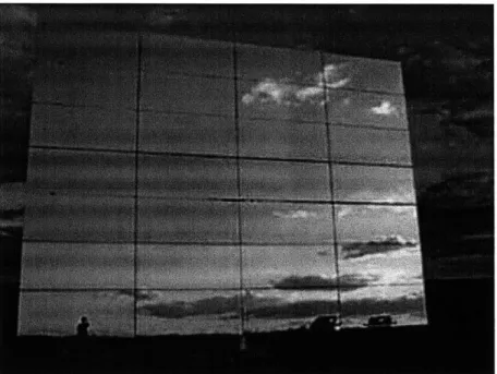
Heliostats have been proven to have some helpful and effective applications. One of these applications
can be seen in Figure 1 below. The photo shows a solar power tower. There is an array of heliostats
surrounding the tower. They serve to direct sunlight to a determined target on the tower. Early designs
of solar power towers were used to heat water and use the resulting steam to power a turbine.
However, new solar power tower projects use molten salts as heat transfer fluids. These salts have a
high heat capacity. Thus, the thermal energy can be stored and used to boil water to power a steam
turbine during the times of day when the sun is not shining.
Figure 1. An installed heliostat from PS10 Project. Courtesy of www.energyenviro.fi
There are many of these solar power tower projects which is what represents the most extensive use of
heliostats. However, heliostats have also been used for household applications such as water heating
and daylighting which serves to reduce dependence on coal and electricity.
2Design Evolution
It is very important to develop a functional design for the heliostat demonstration. There were a few
main goals of the design:
1- The design would consist of an apparatus that would be able to hold a mirror in a stable
position
2- The heliostat should be flexible in rotation about the z-axis and the x-axis in order to allow
the apparatus to be adjusted in accordance with the position of the sun
3- The apparatus should be able to be recreated by high school students using the available
tools and machinery available in their respective facilities.
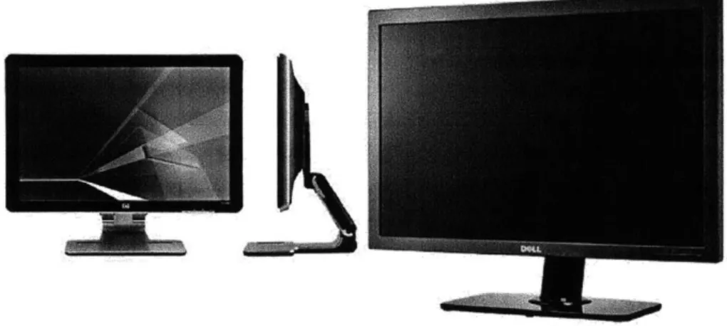
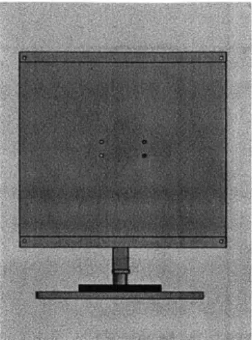
My design was influenced by the design of some computer monitors such as that shown in Figure 2.
Figure 2. HP Computer Monitior (www.highdisplav.com), Dell Monitor (www.engadget.com)
In the first design of the heliostat, the key benefit was the flexibility of the structure. The key parts of
this design included:
- Square aluminum plate base to maintain stability
- Bearing pressed into base to allow rotational freedom
- Hollow square extrusion with spring pins as shaft to allow for adjustable height
- Mirror to reflect light from sun
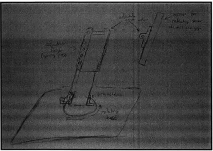
The problem with this design, shown in Figure 3, was that it lacked to ability to be locked into fixed
positions. In order to resolve the problems with the design, I proceeded by focusing on the base and
head of the heliostat separately.
Figure 3. Initial Project Design
Base Design
The key factor for the redesign of the base was that the rotational position of the shaft should be able to
be fixed. The first concept is shown in Figure 4. This concept implements the use of pegs to fix the
position of the shaft. An arm is connected to the body of the square shaft. It serves to sit between the
spaces of the pegs and thus fix the position of the shaft.
Figure 4. Base Design Concept 1
A similar concept is shown in Figure 5. In this concept, a disc is attached to the body of a circular shaft.
Instead of using pegs, there are screw holes in the base. These holes serve to allow screws that
penetrate the disc to be screwed into the base thus fixing the position of the shaft.
Figure 5. Base Design Concept 2
The problem with these concepts is that they restrict complete rotational freedom of the shaft, and so
the concept shown in Figure 6 was developed. This concept implements the use of a medium hard
rubber that is attached to the base. The screws that penetrate the disk can now fix the shaft in any
position. In the final design of the base, the disk is omitted and the screws are simply attached to
L-braces that are connected to the shaft.
Head Design
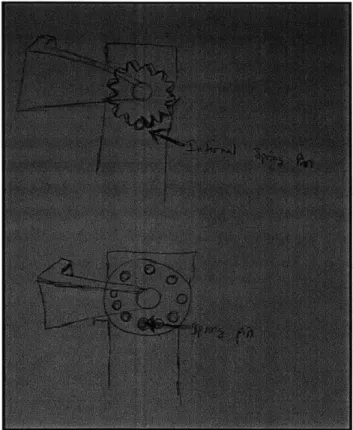
The key problem of the head design was fixing rotational position of the mirror. The concept that is
shown in Figure 7 implements the use of spring pins in a hollow square shaft to fix the position of the
mirror. Two options for using the spring pins are shown where the pins can either be fixed in holes or
slots of a separate circular piece attached to the shaft. The biggest problem with this design is that the
building of the separate piece would require water-jet machining to manufacture. While I am proficient
in the use of, and have access to, a water-jet machine, typical high school machining facilities have not
water jet machines.
Figure 7. Head Design Concept 1
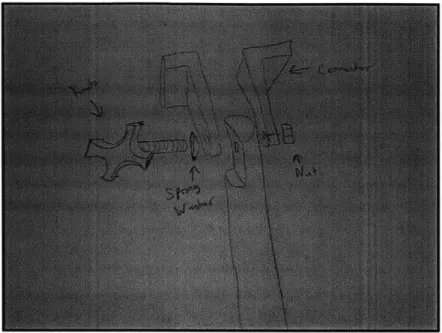
The final design uses the concept shown in Figure 8. In this concept, a knob is attached to the shaft. The
knob, in conjunction with spring washers allow for the easy repeated loosening and tightening of the
rotational position of the mirror.
Figure 8. Head Final Design
Mirror
The heliostats are being made in order to conduct an experiment where the heliostats direct sunlight
into a bucket of water, thus raising the temperature of the water through heat transfer. The mirrors
used, like mirrors that are used in large-scale heliostat projects, are non-concentrating mirrors. The
image or reflection area of the sunlight is approximately the same as the mirror size because the mirrors
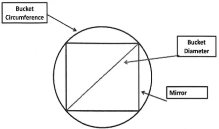
are flat and the distance between the mirror and the receiver is small. The size of the mirror must be in
accordance with the size of the bucket used such that the area of the mirror fits into the circumference
of the bucket. Thus, no solar thermal energy is reflected outside of the bucket and wasted. If the
diameter of the bucket is set to be the diagonal of a square, the length of a side of that square can be
determined. In this case, we are using a bucket with a diameter of 20 inches. Now, when this diameter is
divided by 20.5 (since a square is made up of two isosceles right triangles), we find that the mirror should
be a square with a side length of 14 inches.
Bucket
Circumference
Diameter
Mirror
Figure 9. Mirror sizing visualization
The mirror is to be held in place using two pieces of right-angle extrusion in conjunction with a piece of sheet metal that serves to be a back plate for the mirror as shown in Figure 10.
Final Design
The final design of the heliostat is shown in Figure 11. Unlike the original design, this heliostat design
does not incorporate the concept of a structure with adjustable height. However, the design does satisfy
the conditions of being able to maintain a fixed position and hold an adequately sized mirror while
maintaining the ability to track the position of the sun in two axes.
Structural Stability Analysis
One source of concern is the stability of the heliostat. It must be ensured that the weight of the mirror
will not cause the heliostat to flip over.
x
mirror
Origin
Center of Mass
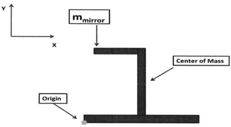
Figure 12. Structural Stability Free-Body Diagram
The heliostat can be represented by the free-body diagram shown in Figure 12. The diagram represents
the weight of the mirror as a point mass at the tip of the connector between the shaft and the
backplate. For the stability calculation, the center of mass of the structure must be determined. The
origin is set at the bottom left corner of the base to serve as a reference point. The center of mass is
found using the following equation:
m1x1 + m2
x
2 + ---mnxn
Xcm-Mtotal
mlyl + M272 + --- mnn
- Mtotal
The variables, xem and ycm, denote the center of mass in relation to the x-axis and y-axis, respectively. The
variable, me, denotes the mass of the respective various components of the structure. The variables, x,
and yn, denote the distances of the components from the set origin in the x-axis and the y-axis,
We may now calculate the torques about the center of mass as exerted by the force of the mirror and the weight of the base. If the torque applied by the load from the mirror and backplate exceeds the counter-torque from the base of the structure, the heliostat will flip over. The following moment
analysis will allow us to determine mmir.ror, the mirror mass required for the heliostat to flip over.
M = 0 = TBase - TMirror
TBase TMirrorM
Fbase = mbase * 9
Fbase * lbase = Fmirror * Imirror
'base
FMirror mBase * 9 *
IMirror lbase
mmirror = mBase * 'Mirror
The load required to flip the heliostat can be found using the following variable values: mes= 3.1 kg,
Ibase= .30 m (1 ft), lmirrr= .10 m (.33 ft). Therefore, the load, mMirror, required to tip the heliostat over is 2.8 kg. The load of the mirror in our design is about 1.4 kg which offers a safety factor of 2.
Heat Transfer Analysis
Steady-State Analysis
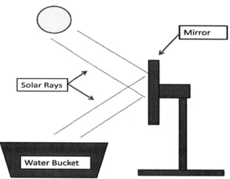
The most important part of this project is the transfer of thermal energy. A model of the system is
shown in Figure 13. There will be an array of heliostats that focus the sunlight on a bucket of water in
order to heat the water, thus demonstrating heat transfer from the heliostat.
0
Mirror
Solar Rays]
Figure 13. Heat Transfer Visualization Model
We must now determine the amount of mirrors that are needed to successfully maintain a water
temperature that is 30*C higher than the ambient temperature. This can be found by using a
steady-state analysis of the system where the amount of energy entering and leaving the system is equal.
Qin
=
out
= Ah * qsun 7rabs
Qout hconv * Abucket *w - Tamb)
Ah = hconv * Abucket *
(Tw
- Tamb) qsun * ?labsIn this analysis, the variable, Q,, represents the energy entering the system as thermal energy from the
sun. The variable, Qut, represents the energy leaving the system through convection between the air
and the water. The variables, Ah and Abucket, denote the collective area of the array of heliostat mirrors
and the area of the mouth of the bucket, respectively. The bucket used for this project has a diameter of
Dbucket= 21.25 in (0.54m). Therefore the area of the bucket is:
Abucket bucket = 0.23 m2
4
The variable qsun denotes the thermal energy from the sun which is approximated at a value of 250 W/m 2
(See Appendix E). The variable, labs= 20-70%, is the total collection efficiency. The dominant
losses are the projection efficiency of the heliostats (cosine loss), the losses due to imperfections in tracking the sun's position, the reflectivity of the mirrors and the absorption efficiency of the water. It is known that the reflectivity of the mirrors is 83 percent. The remaining losses, which depend greatly on the arrangement of the heliostats, are difficult to calculate and were guessed to be about 15%. The variables, T. and Tamb, denote the steady-state temperature of the water and the ambient temperature
of the surroundings, respectively. In this case the values were set to be Tw=500 C and Tamb= 200C. The
water will never be able to reach this steady state temperature, Tw=500C. Instead the plot of the
temperature of the water will be asymptotic to the temperature. The convective heat transfer
coefficient, hconv, between water and air is 20 W/m2K, which is the case of natural convection between a gas(air) and a liquid(water).3
This leaves the necessary area of the heliostats, Ah, is .96 M2. Each heliostat has an area of .126 M2
, so the number of heliostats needed, Nh, is:
Nh A 7.6
.126m2
Therefore, eight heliostats will be constructed.
Transient Heating Analysis
In order to show the functionality of the heliostat, it is important to show the rate of heat transfer that the structure allows. The following equation is used to represent the transient heat transfer.
dT
m,* c * * =
Qin
-QOU(TW)
In this equation, the variable, mw, denotes the mass of the water in the bucket which we will allow to be 40 kg. The variable, cw, denotes the specific heat of water which 4186 J/kg-K. When this differential equation is solved, we get the following equation (derivation shown in Appendix A).
( -hconv Abuckett ) hconv* Abucket- -in (B-C*T i)
*e
Mw*c. e mw*cw c
(Af * qsun * ?labs) + (hcony * A bucket * Tamb) (ecovbkt*vAcetilB-T)
hconv * Abucket hconv * Abucket
m* * cw
Where:
Ti = Tw(t = 0)
A,
* qsun * 7labs + hconv * Abucket * TambMW * cW
C = hconv * Abucket
m, * c.
This equation yields the following plot shown in Figure 14 to represent the theoretical transient heating of the water.
Transient Heating by Heliostat
60 40 40 E 30 I 20 10 -0 50 100 150 200 Thousands Time (s)
The plot shows the water reaching a steady state temperature of about 51.20C. The ambient
temperature was set to 200C, and the initial temperature was set to 50C. The mass of the water is set to
be 40 kg. Unfortunately, according to the model predictions, the water takes multiple hours to reach a steady state temperature. In other words, it takes too much time to reach the above calculated steady-state temperature.
In order to increase the rate of temperature increase, the mass of the water may be reduced to 5kg to give the plot shown in Figure 15. The addition of more heliostats would increase the amount of energy
entering the system and thus increase the steady state temperature. However, these are basic heat transfer calculations, and the plot has not been validated with detailed models or experiments.
Transient Heating Analysis, m,=5 kg
60 40 * 30 0 0 20000 40000 60000 80000 Time, s
Fabrication
In order to build this array of heliostats, the following set of materials is needed (quantity is shown in parentheses):
- 6061 aluminum shafts, 6 feet length, one inch diameter (2), $70
- 6061 aluminum 90 degree angle extrusion, 8 feet length, 2" x 4", .25" thickness(1), $100 - 6061 aluminum plate, 12" x 12" x .5" (8), $320
- 6061 aluminum sheet, 36" x 36" x .125" (2), $170
- Stainless Steel Ball Bearing, ID: 25 mm, OD: 42 mm, Thickness 9 mm, (8), $140 - 6"x6" medium hard rubber (8), $87
- 6061 aluminum 90 degree angle extrusion, 8 ft. Length, .75"x.75", .125" thickness (3), $45 The approximate cost of materials for this array of heliostats is $1,000.
Base Plate
The base plate is the heaviest part of the heliostat. The weight of the base plate ensures that the heliostat will not tip over with the weight of the mirror. It is made using the 12" x 12" plates. The only machining that needs to be done for the base plate is making a hole in the plate in which a bearing will be placed. There are two options for doing so.
The first option uses a drill press. You begin with a center drill to mark the center point on the plate (at 6" x 6" from any corner of the plate). You then drill a through hole (a hole that completely penetrates the plate) with a quarter inch drill. Now, increase in drill size diameter by 5mm increments up to 40 mm, and then increase by 0.5mm up to 42mm, which is the outer diameter of the bearing. The bearing should barely fit into the hole. More concretely, the diameter should not be more than 1/1000 of an inch greater than the bearing diameter.
The second option, which I used, uses a CNC mill. You use a .75 inch end mill to cut a hole in the plate. Set the machine cutting speed to about 1200 rpm. Set the program on the machine to cut a 42 mm hole in the center of the plate. In order to mark the center, you must use an edge-finder to set your origin at a corner of the plate. Then, using the readings on the machine, move the cradle so that the plate is moved to the 6" x 6" position. You then set that point as your origin. Once you have set your origin to the center of the plate, you can install the end-mill into the machine. You may then start the program, but do not move the mill into the plate yet. The reason for this is that most machines have the end-mill jump to a start position before beginning the program. Once the end-end-mill jumps and starts the program, press "hold" on the machine, then lower the end-mill into the plate by 3mm. Once the mill has finished machining a hole of 3 mm depth, raise the mill out of the plate. You may now repeat the process until the hole through the plate is completed.
Figure 16. Base plate model
Back Plate
The back plate is simply the part of the heliostat that supports the mirror. It is made using the 36" x 36"
aluminum sheets. You must use a vertical bandsaw to cut the sheet into eight pieces that have 14" x 15"
dimensions. You then drill holes in the plate according to the technical drawing in Appendix B. You must
use a drill press and F-drill bit (.257 inch diameter). This is the standard drill bit for a through hole for a
screw with a 0.25 inch diameter.
Next, the mirror holders, which are to be attached to the back plate later, are made using the .75"x.75"
extrusion. Simply use the horizontal band-saw to cut sixteen pieces each of 15" length. Then, use the
drill press and an F-drill bit to drill holes in the required places according to Figure 15.
Figure 17. Mirror Holder Hole Location.
Shaft
The shafts for the heliostats require the most machining. First, you must use a horizontal band saw to make eight shafts of 12" length out of the two 6-ft shafts. Then, on a lathe, face the ends of the shaft. You must also cut into the shaft about .002 inch for a length of 0.5 inch from one end of each shaft. Then, on a mill, use a .75 in end-mill to cut a flat face on the circumference of the shaft. You should cut down the shaft 3.0 inches from the end of the shaft that was not cut into on the lathe. The mill should be at a depth of .1875 inches from the edge of the shaft. Then, use a center drill to mark a hole at 1.25 inches from the edge of the shaft on the flat face. Then use a W-drill bit (.386 inch diameter) to cut a hole through the shaft. It is important that the drilling process occurs right after the milling process to ensure that the shaft does not change position so that you will not drill at an angle. The shaft is only milled on one side so that the students do not have to worry about turning the shaft exactly 180 degrees to mill parallel surfaces.
Back Plate to Shaft Connectors
These pieces are made using the 2" x 4" angle extrusion. You must first use the horizontal band saw to cut out sixteen pieces each of 3 inch length. Then, using the drill press, you will need to drill holes in each piece. The holes on the 2" face require an F-drillbit, and the hole on the 4" face requires a W-drillbit. Use a belt sander to curve out the corners of the pieces. This is to allow for safety and easier rotation on the shaft.
Figure 19. Model of shaft connector
Shaft Rotation Lock
The next set of pieces that will be made will allow the shaft to maintain a fixed position. First, using the horizontal bandsaw, cut sixteen pieces from the 2"x4" extrusion, each of 1" length. Then, using the vertical band saw, cut 1.75" off of each piece from the side with 4" length to make each piece have 2"x2.25"xl" dimensions. Now, on the 2.25" side, use the drill press and a 7-drillbit (0.201" diameter) to drill a hole in each piece. Then, use a .25-20 right-handed tap-screw to tap the hole.
The other piece that must be altered is the rubber. Simply using a blade (such as a box cutter), cut a 1.625" hole in the center of each rubber piece. Figure 19 below shows a example of how to cut the rubber.
Figure 20. Rubber cutting example
The shaft lock will look like the picture shown in Figure 21. Thumbscrews that are screwed into the
L-brackets will lock the position of the heliostat when screwed into the rubber. When altering the position
of the heliostat, the screws are unscrewed from the rubber wherein the rubber can return to its normal
state and the heliostat is free to rotate.
Assembly
Now that all of the parts have been made, the heliostats can now be assembled. The fasteners needed for assembly include:
- X-20 shouldered thumb screws (50) - X-20 jam nuts (64)
- %-16 jam nuts (8) - Y-20 round head screws
- %-16 threaded stud knob, 2" stud length (8)
- High-Carbon Steel Belleville Disc Spring .380" ID, .750" OD, .056" Thick (32) - 5 minute epoxy
The first thing that must be done is that the bearings must be press-fit into the hole in the base plate. You must be sure that the bearing does not go beneath the bottom face of the base plate. At this point, you should also adhere the rubber to the top of the plate. The rubber should have an adhesive backing,
but if this is not so, you may use the epoxy. Note that initially plastic bearings were used but they did not prove sturdy enough, and the epoxy used to glue them (instead of press-fitting) to the base plate was not strong enough.
Now, you must use the epoxy to adhere the pieces made for the shaft rotation lock to the shaft. They must be attached such that the two-inch side is attached to the shaft in an upright-L position. They should be attached at 1.75 inches from the base of the shaft. Next, the shaft must be press-fit into the bearing (which is in the plate). You must be sure that the shaft does not go beyond the bottom face of the base plate.
Now, the shaft-backplate connectors can be connected to the shaft. On the flat side of the head of the shaft is where the knob will be. The sequence of parts is the following: knob, 2 nested spring washers, connector, 2 nested spring washers, shaft, curved washer, and connector (with %-16 jam-nut glued around hole). The spring washers should always have their cones facing the connector. The friction from the force of the spring washers under compression prevents the connectors from rotating about the head of the shaft. The reason that the washers are in a nested position is that the force exerted by the washers is doubled under compression.
Now, the back plate is connected to the connectors using the round head screws. Next, the mirror holders are connected to the back plate using the shouldered thumb-screws. The design is such that the mirror can now be added or removed from the heliostat by loosening the thumb-screws in the back plate.
It is important that the measurements and instructions are followed very closely because a small error in
measurement of about 0.1 inch could result in the parts not fitting together for assembly. The final
product should look like the heliostat shown in Figure 22.
Figure 22. Final heliostat product with 18-inch ruler for size reference.
Conclusion
Once the heliostats are created, tests can be run to compare the experimental results of heating the
water with the theoretical results. Furthermore, you will be able to run multiple tests and alter the
parameters of the experiment to observe how they affect the results. In the test set-up, the heliostats
are arranged around a bucket of water. It is important that you avoid any obstructions from the sunlight,
such as trees or buildings.
The main lessons to learn from this project involve the design and fabrication processes. The project
shows how much theoretical work goes into the design process before being able to fabricate a product.
This is the most important step for an engineer because it saves time and money. It is important that an
engineer perform the necessary calculations to be sure that what is built will satisfy the various
specifications.
The fabrication process demonstrates how various machines may be used. It is important that the order
of operations is follow to ensure the completion of the final product as well as safety. Through this
process, the students can also learn to understand why the fabrication of heliostats for large-scale
energy projects is so expensive. The cost of such projects is not yet less than the use of coal and nuclear.
However, projects such as this one may lead to a cheaper fabrication and installation process.
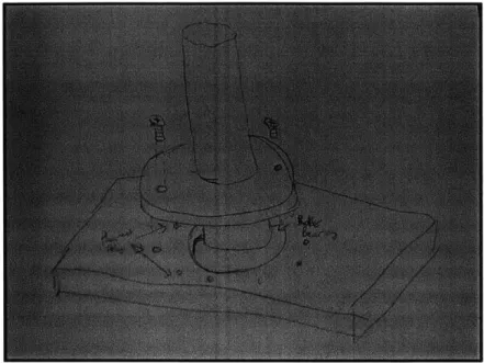
Although the heliostats function as desired, the design could be improved. The main factor that could be changed is the base. The problem is that the shaft requires more than one bearing (at significant
distance from each other) in order to reduce the torque on the bearing in the base plate. Plastic bearings did not work in this design because they cannot withstand such applied torques as steel bearings. A solution could be to use instead a heavy aluminum cylindrical column as the base (instead of the base plate). In this case, the bearings could be press-fit into the top and bottom faces of the
column, and the shaft could now be placed through these two bearings. A sketch is shown in Figure 23.
Figure 23. Possible improvement to design.
Acknowledgements
The author would like to thank Professor Mitsos for his assistance and advisory through the execution of this project. The author would also like to acknowledge William Buckley, manager of the Laboratory for Manufacturing and Productivity at the Massachusetts Institute of Technology, for his assistance in the fabrication process.
Appendix A
dT,
m* cw * -= Qin -
Qaut(Tw)
d t
d T
* c* = Ah * qsun * flabs - hconv * Abucket *
Ah * qsun * 7 abs + hconv * Abucket * Tamb hconv * Abucket * T,
MW * cw m, * c, MW * cW
Ah*q*****b" +hconv Abucet .Tamb
(Tw - Tamb) C = conv*Abcket mw*cw Then: dTw = dt B C*T, dt= dT B-CTw W Integrate: t + D = -In (B-C*T,) C B-(e-CD*e-ct) C Initial condition: T. (0) = T, D _ -In (B-C*T) C d Tw dt Let: B =
Appendix B
Backplate
This drawing shows where to drill the holes that allow the back plate to be connected to the shaft
connectors.
Appendix C
Shaft Connector
Appendix D
Appendix E
Nfet surface solar radiation Annual mean
500 25 225 200 125
~100
80 40I30
20 10Sources
1- Kolb, G. J., et. al., Heliostat Cost Reduction Study, Sandia National Laboratories, SAND Report and ASME Conference Paper
2- www.redrok.com