Design and experimental study of thermal
control system for AMS cryocoolers
The MIT Faculty has made this article openly available.
Please share
how this access benefits you. Your story matters.
Citation
Wang, NaiHua, Burger Joseph, and Lin Cheng. “Design and
Experimental Study of Thermal Control System for AMS
Cryocoolers.” Chinese Science Bulletin 58.10 (2013): 1200–1204.
As Published
http://dx.doi.org/10.1007/s11434-013-5704-7
Publisher
SP Science China Press
Version
Author's final manuscript
Citable link
http://hdl.handle.net/1721.1/105929
Terms of Use
Article is made available in accordance with the publisher's
policy and may be subject to US copyright law. Please refer to the
publisher's site for terms of use.
© The Author(s) 2013. This article is published with open access at Springerlink.com csb.scichina.com www.springer.com/scp
*Corresponding author (email: [email protected])
Engineering Thermophysics April 2013 Vol.58 No.10: 12001204
doi: 10.1007/s11434-013-5704-7
Design and experimental study of thermal control system for AMS
cryocoolers
WANG NaiHua
1, JOSEPH Burger
2& CHENG Lin
1*1
Institute of Thermal Science, Shandong University, Jinan 250061, China;
2 Laboratory for Nuclear Science, Massachusetts Institute of Technology, Boston MA02139, USA
Received May 2, 2012; accepted October 30, 2012
The Alpha Magnetic Spectrometer (AMS) is an instrument for the international scientific experiment, composed of six detectors and 650 micro-electronics. The objective of AMS experiment is to search for dark matter and anti-matter in space. In this paper, the thermal control system for AMS cryocoolers is designed, analyzed and experimentally studied. Using loop heat pipes (LHPs) as the main heat dissipation component, the thermal control system has sufficient heat dissipation capability to prevent the cry-ocoolers from over temperature (+40°C) in hot environment, meanwhile to ensure temperatures of the crycry-ocoolers higher than their lower limit (−20°C) in cold environment. Experiment results show that the thermal control system for AMS cryocoolers functions stably satisfying design specification.
Alpha Magnetic Spectrometer, cryocooler, thermal control system, loop heat pipe
Citation: Wang N H, Joseph B, Cheng L. Design and experimental study of thermal control system for AMS cryocoolers. Chin Sci Bull, 2013, 58: 12001204, doi: 10.1007/s11434-013-5704-7
Alpha Magnetic Spectrometer (AMS) is one of the greatest scientific projects around the turn of the century as well as the first large-scale experiment in space. The main objective of AMS experiment is to search for dark matter and anti- matter [1]. AMS consists of a magnet and six detectors with ultrahigh accuracy which includes Transition Radiation De-tector (TRD), Silicon Tracker (Tracker), Time of Flight (TOF), Ring Imaging Cerenkov Detector (RICH), Electro-magnetic Calorimeter (ECAL) and Anticoincidence Coun-ters (ACC) [2,3].
The power consumption of AMS is 2500 W which is dis-sipated as heat. Thermal requirements of the detectors and electronics are very strict. Meanwhile, different areas of the AMS are subjected to rapid varying direct solar illumination alternating with exposure to deep space which makes the thermal environment more complex. Hence, the technology and quality of the thermal control system is crucial, which determine operational condition, duration and reliability of AMS.
1 Design of the thermal control system for
AMS cryocoolers
AMS includes four stirling cryocoolers (CCs) provided by NASA Goddard Space Centre, which extract parasitic heat from the thermal production shields locating around the helium cooled AMS magnet. During operation, each cry-ocooler consumes 60 W (minimum), 100 W (nominal) and 150 W (maximum) along with heat lift from the cryogenics system 3, 5 and 8 W respectively. The input power together with heat lift is dissipated through the thermal control sys-tem. The thermal control system must have sufficient heat dissipation capability to prevent the cryocoolers from over temperature (+40°C) in hot environment, meanwhile ensure temperatures of the cryocoolers higher than their lower limit (−20°C) in cold environment. Loop heat pipes (LHPs) are passive two-phase thermal transport devices, which utilize vaporization latent heat of a working fluid to transfer heat, and the surface tension forces formed in a fine-pore wick to circulate the working fluid. They possess all the main
ad-Wang N H, et al. Chin Sci Bull April (2013) Vol.58 No.10 1201 vantages of conventional heat pipes. Moreover, owing to
flexible arrangement and special properties of the capillary structure they are capable of transferring heat to long dis-tance efficiently. Accordingly, the thermal control system for AMS crycoolers is based on LHPs with propylene as heat carrier. Each cryocooler has one independent thermal control system composed of two redundant (left and right) LHPs symmetrically attached on both sides of the cryocool-er reject collar. Each LHP consists of an evaporator coupled with the cryocooler reject collar, a compensation chamber, a liquid line, a vapor line, a bypass valve, a bypass line and a condenser (Figure 1). Condenser is integrated into the radi-ator sub-panel. Four radiradi-ator sub-panels have identical con-figuration and condenser layout. The overall shape of four radiator sub-panels is octagonal which is called zenith radi-ator. Heat is dissipated from the cryocoolers to LHPs, zenith radiator and then deep space (Figure 2).
Evaporators of LHPs in this paper utilize unique struc-ture of primary wick and secondary wick. The primary wick provides high capillary transport capability by using sin-tered porous material of nickel powder with very small pore diameter. The secondary wick is made of stainless steel mesh of large pore diameter to decrease pressure drop of liquid flow from the compensation chamber to the evapora-tor [4,5]. A passive bypass valve is employed regulating mass flow from the evaporator to the condenser to protect the cryocooler from low temperature [6]. In cold environ-ment, if the vapor temperature outlet the evaporator is too low, the bypass valve will open to let part of vapor return to the compensation chamber through bypass line directly. When the vapor temperature of the evaporator outlet ap-proaches −20°C, the bypass valve will open completely, all vapor will return to the compensation chamber and no flow to the condenser to ensure the temperature of the cryocooler collar higher than −20°C. The LHP is also equipped with one heater of 6 W on both sides of evaporator fins. When the cryocooler is off under low orbit temperature, heaters
Figure 1 Scheme of loop heat pipe. 1, Evaporator; 2, vapor line; 3,
con-denser; 4, liquid line; 5, compensation chamber; 6, reject collar; 7, bypass line; 8, bypass valve.
Figure 2 Layout of AMS-02 cryocooler LHPs system.
can keep the cryocooler above the minimum survival tem-perature (−40°C). Also, heaters can assist startup of the LHP. Xin et al. built a system level model to simulate oper-ation of the cryocooler thermal control system during mis-sion time of AMS on board the ISS. Results showed that in 21 typical orbit environment cases, without any power input, the thermal control system of cryocooler can dissipate heat load through the zenith radiator to deep space effectively and reliably [7].
2 Performance test
Comprehensive performance test was carried out in clean room at European Organization for Nuclear Research (CERN) after final integration of AMS. The cryocoolers together with corresponding thermal control systems were put into operation. The environment temperature was kept at 21±1°C. The experiment system is shown in Figure 3. Four fans were installed at each corner of the zenith radiator. All the cryocoolers and components of LHPs except con-densers were wrapped with multi-layer insulation. Powers of cryocoolers were recorded automatically through AMS data acquisition system. Reject collar and evaporator tem-peratures on both sides of the cryocooler were measured with DS18S20 dallas sensors, collected by the global tem-perature sensor network (GTSN) of AMS. Accuracy of dal-las sensors in the range of −10°C to +85°C was ±0.5°C. There were two measure points of the condenser inlet, mid-dle and exit on the outer surface of zenith radiator, they were measured with two redundant Pt1000 thermal re-sistances with accuracy of ±0.3°C. They were also collected by GTSN of AMS. Average value of the six Pt1000 thermal resistances measurements was considered as LHP heat sink
Figure 3 Scheme of performance test.
temperature.
When the cryocooler switched on with power of 62 and 92 W, both LHPs started up correctly. Startup times were shorter at higher power. As shown in Figure 4, temperatures of reject collars began to increase shortly after the cry-ocooler switched on. Temperatures of evaporators increased first and then dropped quickly. Afterward they became sta-ble. This phenomenon indicates LHPs started up and work-ing fluid inside the evaporators was vaporized. The evapo-rators were cooled down quickly. At the same time, vapor flowed into condensers and heat was dissipated to the zenith radiator.
Nucleation of working liquid in the wick needs a certain degree of superheat (temperature difference between working
Figure 4 Startup of LHPs (a) 62 W; (b) 92 W.
fluid outside the evaporator wick and inside the compensa-tion chamber) when the vapor removal channel is flooded with liquid [8]: sat v l sup lv cap 2 T v( v) T h r , (1)
where Tsup is superheat degree needed for nucleation (K),
is surface tension (N/m), Tsat is saturation temperature
(K), v and 1 are specific volume of vapor phase and liquid
phase (m3/g), hlv is latent heat (J/g) of the working fluid,
rcap represents capillary radius of the wick meniscus (m).
During startup, as heat Qin (W) is applied on the evaporator,
the majority of heat input Qevp(W) goes into vaporizing
liq-uid on the external surface of the primary wick and then transports through the vapor line to the zenith radiator. The reminder of heat input transfers across the wick and evapo-rator surface to the compensation chamber which is called
heat leak Qleak (W) to heat sub-cooled liquid from the liquid
line (Figure 5):
Qin = Qevp+Qleak. (2)
Heat leak conducted through evaporator surface to the compensation chamber is less. The majority of heat leak is transferred through the wick. The effective conductivity of
the wick Keff can be expressed as:
eff wick 2 2 (1 ) 2 (1 ) K K , (3)
where Kwick is conductivity of the wick material W/(m K),
represnets the conductivity ratio of liquid fluid to the wick material, is wick porosity (%). Superheat degree needed for nucleation can be reached easier with wick of lower conductivity due to less heat leak. Primary wick of nickel with high conductivity and small pore can decrease thermal resistance between reject collar and evaporation phase interface, and increase working fluid temperature there. At the same time, secondary wick of stainless steel mesh with low conductivity and large pore can decrease heat leak significantly (Figure 6). Both aspects benefit for nucleation superheat establishment.
It can be seen from the test results that the thermal con-trol system can maintain temperatures of the cryocoolers in the range of design specification. Temperatures of reject collars and evaporators were quite stable (Figure 7). As cryocooler power increased, temperatures of the reject col-lar and evaporators increased linearly (Figure 8).
Wang N H, et al. Chin Sci Bull April (2013) Vol.58 No.10 1203
Figure 6 Effective conductivity of nickel and stainless steel wicks.
Figure 7 Temperatures of evaporator and reject collar.
Figure 8 Temperatures of evaporators and reject collars vs. power.
3 Loop heat pipes experiment
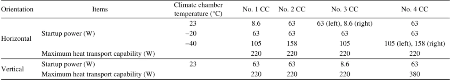
After the performance test of the thermal control system for AMS cryocoolers, experiment was performed to determine startup power and the maximum heat transport capability of LHPs in the climate chamber. The thermal control system of each cryocooler was installed on a supporting frame. The frame was attached to a tilting tool in order to achieve ver-tical and horizontal test orientations. The evaporators of the LHPs were coupled with common block that accommodated a cartridge heater providing thermal power to both LHP evaporators. All the LHP components except the condenser were properly insulated. The experiment results are summa-rized in Table 1.
As shown in Table 1, performances of the LHPs were fi-ne which satisfied thermal requirements. All the LHPs started up correctly at the minimum power (63 W) in both horizontal and vertical orientations. Moreover, both LHPs of No. 1 CC, left LHP of No. 3 CC in horizontal orientation and right LHP of No. 3 CC in vertical orientation started up correctly even at 8.6 W of heater power. The maximum heat transport capabilities of all the LHPs were 220 W, much higher than nominal power 158 W.
The operation characteristics of bypass valve were inves-tigated during thermal vacuum and thermal balance test in the Large Space Simulator (LSS) of European Space Agen-cy (ESA). The power of cryocooler was 140 W. Tempera-tures of LSS shroud and LHPs are shown in Figure 9. It can
be seen that the bypass line temperature Tbl decreased as the
shroud temperature Tshr decreased. At 10:40 on April 5, the
bypass line temperature increased rapidly, the bypass valve began to open and vapor went into the bypass line. After 24 min, the bypass line temperature approached temperatures of the bypass valve and vapor line. The bypass valve opened partially at a stable position. At this moment,
tem-perature of bypass valve Tbv and evaporator Tevp were 0.5°C
and 1.5°C respectively. After the bypass valve opened, as shroud temperature decreased, the bypass line temperature decreased again. But, even the shroud temperature decreased till −90°C, the evaporator temperature was stable at around −10°C, which was far away from lower limit (−20°C).
The shroud temperature started to rise from −90°C with a slope of +5°C/h at 9:25 on April 10, the bypass valve
Table 1 Startup power and maximum heat transport capability of LHPs
Orientation Items Climate chamber temperature (°C) No. 1 CC No. 2 CC No. 3 CC No. 4 CC
Horizontal Startup power (W)
23 8.6 63 63 (left), 8.6 (right) 63
−20 63 63 63 63
−40 105 158 105 105 (left), 158 (right) Maximum heat transport capability (W) 220 220 220 220 Vertical Startup power (W) 23 63 63 8.6 63
Figure 9 Bypass valve operation characteristics.
closed gradually and evaporator temperature increased. The bypass line temperature dropped rapidly when the shroud temperature reached −38.9°C indicating the bypass valve closed completely. At this moment, bypass valve
tempera-ture Tbv and evaporator temperature Tevp were −2.6°C and
0.5°C.
The set temperature Tset represents the point where the
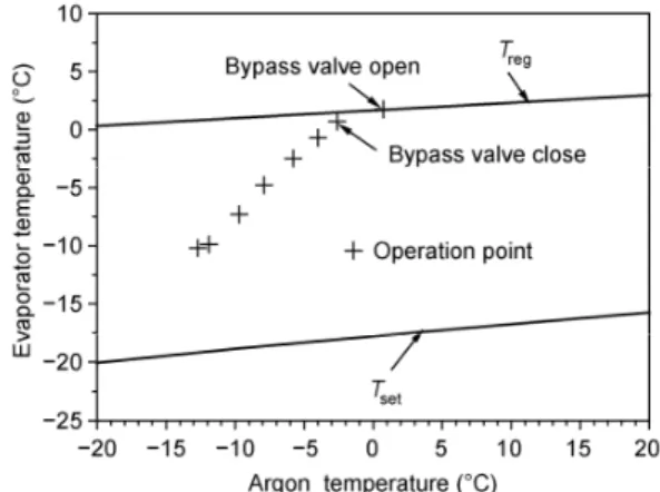
valve opens the bypass path completely and consequently, the radiator branch is completely closed. The nominal value of the set temperature is −20°C. The bypass valve operates as a function of the evaporator saturation pressure and tem-perature, but not the heat load applied [6]. The bypass valve has three operation modes (off, regulation and on). If there is enough evaporator heat load to start up the LHP and the evaporator pressure is higher than the regulation pressure, the bypass valve will close and no mass flow through the bypass line (off mode). If the evaporator pressure is lower than regulation pressure, the valve can allow mass flow be distributed between bypass line and condenser (regulation mode). For the LHP with bypass valve, the evaporator tem-perature cannot be below the set point. If it were the case, mass flow circulation would be established only in bypass line and no flow through the condenser (on mode). No power would be removed and the evaporator temperature should increase higher than −20°C, until the condenser path is open and the bypass valve transits to regulation mode, all thermal loads will be removed in the condenser and then be dissipated to the deep space through the zenith radiator. The actual bypass valve operation condition is that the conden-ser and the bypass valve partially open, the mass flow dis-tributes between them according to fluid pressure. Therefore, in regulating mode, the bypass valve reaches a steady state in an intermediate opening between 0% and 100%. If the argon temperature varies, so does back pressure. The set temperature and regulation temperature shift accordingly. It can be seen from Figure 10, bypass close and open points were near to the regulation temperature line, and other
Figure 10 Evaporator temperatures under different argon temperature.
operation points located between the regulation temperature line and set temperature line. The bypass valve featured fine action repeatability and regulation performance.
4 Conclusions
In this paper, the thermal control system for AMS cry-ocoolers is designed, analyzed, and experimentally studied. The results show that, employing loop heat pipes (LHPs) with the structure of primary wick and secondary wick as well as innovative bypass valve design, the thermal control system for AMS cryocoolers functions stably satisfying design specification. The study of thermal control system for AMS cryocoolers can be used as a reference for similar large-scale scientific instruments.
This work was supported by the Major Project of Technology Transfer of Shandong Province (2009ZHZX1A1105). We thank Carlo Gavazzi Space SpA for cooperation in the experiment.
1 Musser G. The space station’s crown jewel. Sci Am, 2011, 304: 72–73
2 Marsollier A. AMS: The search for exotic matter goes into space. Cern Courier, 2011, 51: 19–21
3 Catapano P. Endeavour takes passion, precision and patience. Cern Courier, 2011, 51: 23–25
4 Xin G M, Cui K H, Zou Y, et al. Development of sintered Ni-Cu wicks for loop heat pipes. Sci China Ser E-Tech Sci, 2009, 52: 1607– 1612
5 Li J W, Zou Y, Cheng L, et al. Experimental study on capillary pumping performance of porous wicks for loop heat pipe. Exp Therm Fluid Sci, 2010, 34: 1403–1408
6 Wang N H, Burgur J, Luo F, et al. Operation characterstics of AMS-02 loop heat pipe with bypass valve. Sci China Tech Sci, 2011, 54: 1813–1819
7 Xin G M, Chen Y, Cheng L, et al. Simulation of a LHP-based ther-mal control system under orbital environment. Appl Therm Eng, 2009, 29: 2726–2730
8 LaClair T J, Mudawar I. Thermal transients in a capillary evaporator prior to the initiation of boiling. Int J Heat Mass Transfer, 2000, 43: 3937–3952
Open Access This article is distributed under the terms of the Creative Commons Attribution License which permits any use, distribution, and reproduction