Design And Testing Of A Facility
To Study Mixing Augmentation
In Reacting Flows
byPatia J. McGrath
B.S. (Mechanical Engineering), Columbia University, 1993
Submitted to the Department of Aeronautics and Astronautics
in Partial Fulfillment of the Requirements for the Degree of
Master of Science
inAeronautics and Astronautics
at theMassachusetts Institute of Technology
February 1995
C 1995 Patia J. McGrath
All Rights Reserved.
The author hereby grants to MIT permission to reproduce and to distribute publicly paper and electronic copies of this thesis document in whole or in part.
Signature of Author
Signature of Author Department of Aeronautics and Astronautics January 20, 1995
Certified by_
- /- Professor Ian A. Waltz Thesis
Supervisor-Accepted by
A t Professor Harold Y. Wachman Chairman, Department Graduate Committee
Aero
Design And Testing Of A Facility
To Study Mixing Augmentation
In Reacting Flows
byPatia J. McGrath
Submitted to the Department of Aeronautics and Astronautics in Partial Fulfillment of the Requirements for the Degree of
Master of Science in Aeronautics and Astronautics
Abstract
A combustion facility incorporating an annular burner was designed and constructed. This facility serves as a means by which the effects of mixing enhancement associated with lobed mixers in a combusting flowfield may be investigated. A turbulent, diffusive, momentum-driven flame from an atmospheric burner was desired for this mixing research; additionally, the facility was required to be one-person operable and largely automated. These factors motivated the
consideration of various design requirements and constraints in order to achieve suitable conditions for mixing augmentation studies. Issues examined concerned combustion and flow phenomena, as well as the operation and features of the facility hardware. The resulting burner design allows for mixing between two co-flowing axisymmetric streams, and includes several features which allow for flowfield manipulation. The most essential of these is the core nozzle which may be
interchanged between baseline and lobed configurations, thereby providing for mixing augmentation control. Velocities of the two co-flowing fluid streams, as well as the composition of the fuel mixture, are varied and monitored through the facility flow control system. The performance of the facility was examined with respect to the requirements for the establishment and observation of a combusting flowfield
appropriate for enhanced mixing research. It was found that though the flow system operates safely and is fully functional, the flow rates generated are too low in
comparison with those desired for this lobed mixing research effort. Recommendations to correct this problem are made.
Thesis Supervisor: Ian A. Waitz
Acknowledgements
The completion of this thesis and my existence at MIT would not have been possible without a great deal of help and support along the way. The following people have my sincere thanks and gratitude:
Prof. John B. Heywood, Prof. Shaoul Ezekiel, and Dr. Steven Smith, (each of MIT), and Prof. Vijay Modi (of Columbia University) for their advice, patience, and encouragement
Dick Perdichizzi, Bill Ames, and Jimmy Letendre, for their help in the construction and testing of the facility
Prof. Greitzer, Prof. Waitz, and Dr. Tan -- "Engineers In Action"
Sonia Bhambani, Kathryn Fricks, and Becky Ramer, for their friendship, advice, and willingness to gossip
Erik Pitchal, for putting up with me since high school and for having faith in me for all these years
"Lab Group Number 4" from Columbia University, namely: John Samson, Jack Shih, Darryl Taylor, and Rizzo -- four truly wonderful people who always let me do the theory section, constantly kept me laughing, and have proven that friendships can outlast both Poldesnik's lectures and college graduation
Members of the GTL, and especially Ish Ceyhan, Jan Krasnodebski, Dave Tew, and Ted Valkov, for being kind and helpful to me throughout my stay in the GTL
Michael Russo, without whose help I could not have survived Columbia nor made it to MIT, and whom I shall always admire as a brilliant guy (even though he always
forgets my birthday)
John DeCount, whose kindness and caring have enriched my life and for whose friendship I am truly grateful.
Lastly, this thesis is dedicated to my father, Dr. Francis J. McGrath. Through scores of exams and hundreds of problem sets, he has remained a source of constant and dependable love, support, and comfort. He has taught me the lesson that MIT could not; being a good person is much more important than being a successful
academic. However, through my father's own example, I have learned that it is indeed possible to be both.
Table of Contents
Abstract. . ... . ... i
Acknowledgem ents ... ... 111
Table of Contents ... *iv
List of Tables ... Viii List of Figures ... x Chapter 1 INTRODUCTION ... ... 11 1.1 Overview ... 11 1.2 Background ... 12 1.2.1 Historical Context... ... 12 1.2.2 Lobed M ixers ... 13 1.3 Contributions...14 1.4 Overview of Thesis... ... 15
Chapter 2 FACILITY DESIGN ... ... 19
2.1 Design Motivation.... ... ... 19
2.2 Facility Functional Requirements and Constraints...20
2.2.1 General...20
2.2.1a Test-CellLayout...20
2.2.lb Diffusion Flame ... ... 20
2.2. 1c Gaseous Reactants... o ... . ... 21
2.2.2 The Burner ... ... 21
2.2.2a Lobed Mixing Capability... ... 21
2.2.2b Co-Annular Construction... 21
2.2.2c Observation Length... ... 22
2.2.2d Boundary Layer Thickness... ... 22
2.2.2e Fuel and Oxidant Flowrates... ... ... 23
2.2.2f Flame Stability and Blowoff...23
2.2.2g Turbulent Flame... 26
2.2.2h Radiated Heat... ... 27
2.2.2i Flame Length...29
2.2.2j Momentum-Driven Flame...30
2.2.2k Flow Turbulence Control... 31
2.2.21 Nozzle Contraction... ... ... ... 31
2.2.2m Structural and Machining Requirements... o... ... 32
2.2.3 The Flow Control System...32
2.2.3a Safety... ... ... 32
2.2.3b Flexibility and Control... ... ... ... 33
2.2.3c Exhaust Removal...34
2.2.4 Evaluation... 36
Chapter 3 FACILITY DESCRIPTION AND OPERATION ... 55
3.1 Results of the Design Procedure...55
3.2 The Burner Design... 55
3.2.1 Physical Description of the Co-Annular Burner...55
3.2.2 Burner Structure... 56
3.2.3 The Honeycomb ... 57
3.2.4 Flow Screens...58
3.2.5 Nozzle Design... 60
3.3 The Flow System Design... 62
3.3.1 Physical Description of the Flow System...62
3.3.2 Flow System Safety Features... 63
3.3.3 Regulation Within the Flow System... 64
3.3.4 Control of the Flow System... ... . ... 66
3.3.5 Ignition...66
3.3.6 System Operation...67
Chapter 4 FACILITY TEST AND EVALUATION... ... 83
4.1 Facility Testing Summary... 83
4.2 Test Evaluation...85
4.3 Recommendations Concerning Facility Operation ... 87
Chapter 5 CONCLUSIONS...97
5.1 Summary...97
5.2 Recommendations for Future Work...97
Bibliography ... 103
Appendix A ADDITIONAL BURNER DIAGRAMS...107
Appendix B FLOW SYSTEM CIRCUITRY... ... 111
Appendix C INSTRUMENTATION AND HARDWARE SPECIFICATIONS...115
C.1 Two Way Direct Acting Solenoid Valve...115
C.2 Two Way Pilot Operated Solenoid Valve ... 116
C.3 Minipeeper Ultraviolet Flame Detector... ...118
C.4 Protectorelay Primary Control... 119
C.5 Pressure-Reducing Regulator ... 120
C.6 Power Supply ... ... 122
C.7 Mass Flow Controller ... ... ... 123
C.8 Orifice Plate Mass Flow Controller...124
C.9 Relief Valve... ... .. 126
C.10 Check Valve for 1/4" Line.... ... 127
C. 11 Membrane Filter... 127
C.12 Tee Purge Assembly ... ... 128
C.13 Quarter-Turn Valve...129
C.14 General Purpose Compressed Air Filter ... ... ... 129
C.15 Two-Cylinder Compressed Gas Cabinet...130
C. 16 Flash Arrestor ... 131
List Of Tables
2.1 Principal Operational Quantities Utilizing Hydrogen Fuel... 52
2.2 Principal Operational Quantities Utilizing Ethylene Fuel... 53
3.1 Screen Meshes Available For Experimental Use... .... 72
4.1 Flow Speeds Of Hydrogen For Which Combustion Occurs...91
4.2 Core-Flow Compositions For Which Combustion Occurs With N o A ir C o-Flow ... 9 1 4.3 Combinations Of Hydrogen Core Flow And Air Co-Flow For Which Combustion Occurs; No Nitrogen Diluent... ... 91
4.4a Hydrogen-Nitrogen Core Flow Mixtures With Air Co-Flow For Which Combustion Occurs; Air Flow Being Varied...92
4.4b Hydrogen-Nitrogen Core-Flow Mixtures With Air Co-Flow For Which Combustion Occurs; Nitrogen Flow Being Varied... ... 92
List of Figures
1.1 Lobed Mixer Geometry...17
1.2 Splitter G eom etry... ... 18
2.1 Test-Cell Layout And Dimensions...39
2.2 Illustration Of Shear Layer Impingement And Observation Length... 40
2.3 Illustration Of Bluff Body Flameholding... ... 41
2.4 Maximum Reynolds Numbers For Fuel-Nitrogen Mixtures... 42
2.5 Temperatures Resulting From Radiated Heat... ... 43
2.6 Diffusion Flame Length Variation With Fuel Jet Velocity...44
2.7 Flame Lengths From Fuel-Nitrogen Mixtures... ... 45
2.8 Maximum Froude Numbers For Fuel-Nitrogen Mixtures...46
2.9 Fuel-Nitrogen Mixture Viscosity... 47
2.10 Adiabatic Flame Temperatures For Fuel-Air Combustion...48
2.11 Observation Lengths For Various Core/Co-Flow Nozzle Diameter C om binations...49
2.12 Flow Speed Ranges For Hydrogen-Air Mixtures...50
2.13 Flow Speed Ranges For Ethylene-Air Mixtures...51
3.1 Burner Assembly Diagram... 71
3.2a C ontracted N ozzle... ... 73
3.2b Contracted Nozzle With Straight Outlet Segment...73
3.3 Core Nozzle Diagram...74
3.4 Lobed Core Nozzle Diagram...75
3.5 Lobed Structure Of The Lobed Core Nozzle...76
3.6 Facility L ayout... 77
3.8 Control Panel Configuration...79
3.9 Spark Igniter Configuration...80
3.10 Pre-Run Checklist...81
3.11 Flowchart Of Facility Operations... 82
4.1 Reynolds Numbers Obtained Using Facility-Generated Flow Rates And M ixtures... . . ... 93
4.2 Froude Numbers Obtained Using Facility-Generated Flow Rates And M ixtures... . . ... 94
4.3 Laminar Flame Photographs... 95
A. 1 Cylinder Dimensions... 108
A.2 Co-Flow Nozzle Diagram... ... 109
B .1 Electrical Control Layout... ... 112
B.2 Flow Control System Circuitry Diagram... 113
C.la Two Way Direct Acting Solenoid Valve Dimensions... 133
C.lb Two Way Direct Acting Solenoid Operation... 133
C.2a Two Way Pilot Operated Solenoid Valve Dimensions... 134
C.2b Two Way Pilot Operated Solenoid Valve Operation...134
C.3 Minipeeper Ultraviolet Flame Detector Dimensions ... 135
C.4 Protectorelay Control Circuitry...135
C.5a Pressure-Reducing Regulator Diagram... 136
C.5b Loading Pressure Diagram ... 136
C.6 Power Supply Dimensions... 137
C.7a M ass Flow Controller Dimensions ... 138
C.7b Mass Flow Controller
Structure...138-C.8a Orifice Plate Flowmeter Dimensions ... 139
CHAPTER 1:
INTRODUCTION
1.1 Overview
Mixing enhancement is important for achieving optimal performance from a variety of fluid mechanical devices. This is particularly true in gas turbine engine combustion systems, where the rapidity and spatial uniformity of the fuel-air mixing process directly impacts combustor size and weight, combustion efficiency, and pollutant emissions production.
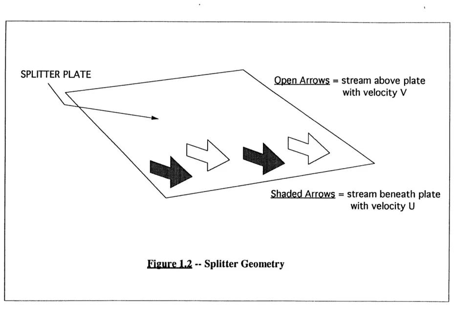
One technology for augmenting mixing between co-flowing streams which has recently received considerable attention is the lobed mixer, shown in Figure 1.1. The lobed mixer enhances mixing beyond that associated with the velocity difference between the two streams on either side of a flat splitter plate, illustrated in Figure 1.2. The lobes are designed both to increase the initial interfacial area between the two fluids through increasing the trailing edge length, and to shed large-scale streamwise circulation. The streamwise circulation acts to enhance mixing by further increasing the interfacial area between the two fluids downstream of the trailing edge.
Many issues are as yet unresolved regarding the performance of lobed mixers in reacting flows. These issues include the influence of heat release on the mixing performance, and the impact of high strain rates on the progression of reactions involving both primary and trace species central in pollutant formation processes. This thesis presents the details of the design and operation of a test facility which will eventually be used to study these effects.
A combustion facility incorporating an annular combustor was designed and constructed. The burner allows either baseline or lobed nozzle geometries to be installed to provide unaltered and augmented flowfields, respectively. Preliminary characterization of the facility performance is provided by the mass flow rates and
combinations of fuel, diluent, and co-flow for which ignition occurs; flame photographs are also included as representations of points within these facility operating ranges.
1.2 Background
1.2.1 Historical Context
Gas turbine combustion systems require not only new innovations, but also old technologies applied in original ways, to satisfy present performance and pollutant emission goals. The fuel and air mixing process plays a critical role in meeting these criteria. Combustion rate and extent are controlled by the level of molecular mixing that has occurred between the fuel and oxidant prior to reaction. Hence, combustion efficiency, heat release rate, and pollutant formation are all established by the mixing process. Augmentation of this mixing process, appropriate to practical applications, provides the general motivation for this research effort.
The evaluation of any mixing process encompasses the following considerations: mixing scale desired, spatial uniformity and rapidity with which the mixing is fulfilled, and resulting stagnation pressure loss. Over the last sixty years, there have been many studies concerning methods to enhance mixing between fuel and air in several types of combustion systems. Lobed mixers are attractive for some applications because they can be used to introduce large-scale streamwise circulation between co-flowing
streams with relatively low momentum loss, as compared to other mixing enhancement technologies. There are several examples of practical uses of this streamwise
circulation to augment mixing, such as between the core and bypass flows of aircraft turbine engines (McCormick and Bennett, 1993; Paterson, 1984), and between the primary and secondary streams of ejectors (Tillman et al., 1992).
focused on planar, unreacting flowfields. Little effort has been put toward the examination of their effects on axisymmetrically co-flowing and combusting streams. This thesis serves as the basis upon which an extensive combusting-flow, mixing augmentation study (Underwood, 1995) will be conducted at the MIT AERL (Aero-Environmental Research Laboratory).
1.2.2 Lobed Mixers
A conventional splitter plate, which shall be referred to as the "baseline"
geometry, is shown in Figure 1.2. For this case, the dominant mixing mechanism is associated with the component of vorticity normal to the flow direction, termed spanwise vorticity. A Kelvin-Helmholtz instability grows with distance from the trailing edge in the fluid interface. For axisymmetric shear layers, a "ring" vortex roll up process comprises the mixing mechanism, corresponding to the spanwise vorticity seen in planar shear layers.
Lobed mixers such as that shown in Figure 1.1 are used to augment the mixing process between two co-flowing streams of different velocities. Two aspects of the lobed mixer flowfield are responsible for the mixing enhancement. First, the trailing edge interface between the two streams has been increased by the lobed geometry. This provides a larger area (for the same flow cross section) over which the spanwise vorticity may act to mix the fluids. Second, a spanwise variation in aerodynamic loading is produced at the mixer trailing edge. Through this nonuniform loading, streamwise vorticity is established and shed downstream of the trailing edge. Downstream mixing is enhanced since the streamwise vorticity stretches the mean cross-flow interface, substantially increasing the area relative to the length set by the lobe geometry.
The convoluted trailing edge sheds a vorticity distribution corresponding to the periodicity of the loading. This causes roll-up of the previously flat wake sheet into
cells one convolute in width. The flow within each cell then winds into counter-rotating vortices.
Hence, both spanwise and streamwise vorticity play a part in the mixing process downstream of a lobed mixer. The growing Kelvin-Helmholtz instabilities in the mean cross-flow interface interact with the streamwise winding process. The streamwise circulation becomes less important in enhancing mixing at approximately ten wavelengths downstream of the trailing edge, where the spanwise undulations have grown to the scale of the streamwise vortices. Downstream of this point the mixing layer behaves much like a planar shear layer.
The facility discussed in this thesis was designed to allow investigation of flow behavior primarily in the region upstream of ten wavelengths, where the streamwise circulation is most effective in augmenting the mixing process.
1.3 Contributions
The contributions of this thesis are:
(1) A one-person operable flow control facility was constructed. Its versatility provides the AERL with a means by which mixing studies may be thoroughly and safely performed.
(2) A co-annular, vertically-standing combustor was designed and built. It allows vorticity levels in the mixing process to be controlled and varied by core nozzle
interchange between lobed and splitter geometries.
(3) The operational ranges of experimental conditions suitable for this mixing research are presented.
1.4 Overview of Thesis
Chapter Two describes the requirements of and constraints upon the facility design. Combustion and flow phenomena pertinent to this research effort, as well as instrumentation issues, are explored in the context of the combustion facility. The chapter subsequently provides operational ranges of experimental parameters wherein enhanced mixing combustion studies would be optimally conducted. Chapter Three presents the principal features and construction details of the burner and flow control system. Chapter Four summarizes the preliminary testing performed on the facility. Chapter Five summarizes the conclusions of this study. Recommendations for subsequent work are also suggested.
L
SPLITTER
PLATE
Open
Arrows = stream above plate
with velocity V
00
Shaded Arrows = stream beneath plate
with velocity U
CHAPTER 2: FACILITY DESIGN
2.1 Design Motivation
The underlying objective of this research is to examine the effects of mixing enhancement associated with lobed mixers in a combusting flowfield. Consequently, the coupled chemical and fluid mechanical characteristics of the flowfield must be controlled to the degree that an adequate environment is established in which mixing enhancement may be studied.
The central component needed to achieve this goal is a combustor. The prime function of the combustor is to provide a flowfield upon which mixing augmentation may be performed. From inlet to burner tip, the combustor serves as a flow
supervisor, accommodating the entrances of both the fuel and oxidant streams, providing a means to straighten the streams, controlling their turbulence levels, and eventually directing the streams into their respective nozzles. The interface between the fuel and oxidant streams may be enhanced by lobed mixers placed at the end of the fuel nozzle.
The flow control system encompasses the supporting hardware and operating procedures needed by the burner to establish an appropriate reacting flowfield. Safe, regulated delivery of fuel and oxidant to the burner inlet is the central focus of the flow control system.
This chapter presents the general requirements and restrictions imposed on the facility, and then examines issues specific to the burner and flow control system designs.
2.2
Facility Functional Requirements and Design Constraints
2.2.1 General
2.2.1a Test-Cell Layout
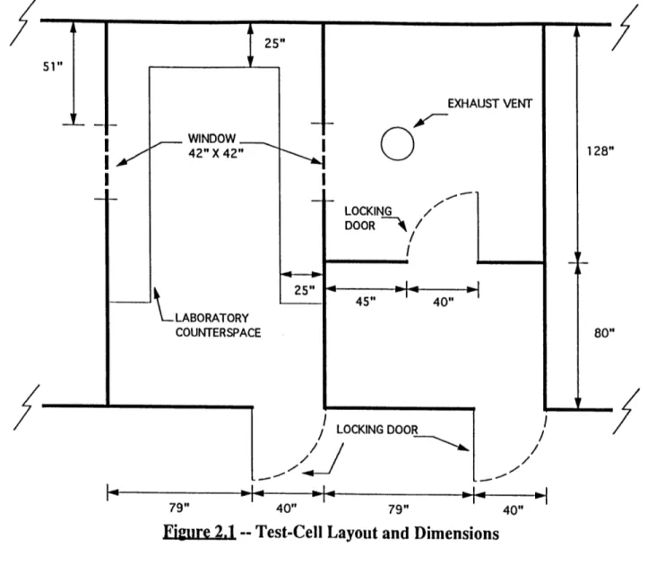
Test-cell size and construction, illustrated in Figure 2.1, places inherent limitations on both the burner and the flow control system design. The ceiling height and the observation window location constrain burner height. The location of the exhaust vent determines burner placement and the layout of the fuel and air delivery system.
Safety demands that the fuel cylinder be stored outside of the test chamber; hence the test-cell ante-chamber is appropriate for the gas storage cabinet installation.
2.2.1b Diffusion Flame
A flame with fuel and oxidant uniformly mixed prior to ignition is defined as premixed. The contrary case, wherein the reactants must diffusively mix together in the combustion zone, is termed a diffusion flame. The latter describes the required
situation in the present experiment, where it is the effect of lobed mixers on this mixing process that is of interest.
Hence, the flow control system must supply fuel and oxidant separately; the burner receives both fluid mediums, but must keep them apart while directing them to the reaction zone. Additionally, it is the mixing process in this reaction zone which must be observed; hence an atmospheric burner (i.e.: where the combustion area is not within the confines of the burner body) is suitable and manageable concerning both functional and diagnostic requirements.
The diffusive, unconfined nature of the flame requires remote access from the test-cell of all controllers and flow indicators. Accordingly, the flow control system must
be operable from the control room adjacent to the test-cell. The test-cell ventilation system must also be capable of removing the pollutants and unburned fuel emitted by the unconfined flame. This restricts burner (i.e.: combustion field) size and requires accurate regulatory control of the fuel flow.
2.2.1c Gaseous Reactants
The oxidant used in these experiments is air supplied by the facility's compressed air line at 0.75 lb/sec. The experiments require gaseous fuels and diluents as well; flow rate requirements are discussed in Section 2.2.4 and Chapter Four. Accordingly, the burner and flow system must be designed to handle gaseous fluids without leakage, and to have instrumentation suitable for measuring and controlling these gases.
2.2.2 The Burner
2.2.2a Lobed Mixing Capability
The ability for the burner outlet to be easily interchanged between lobed and "baseline" geometries is essential for the enhanced mixing experiments. Both configurations must be as similar as possible in all respects, with the exception of absence and presence of lobes on the baseline and lobed nozzle outlets, respectively.
2.2.2b Co-Annular Construction
From the standpoint of experimental diagnostics, a symmetrical flame is desirable. A combustor with a co-annular design provides an axisymmetric flame; it also
supresses effects on the flow stream and flame associated with any corners or sharp edges of the outlet nozzle geometry (i.e.: as with two-dimensional slot-burners) which are undesirable in this mixing study. Additionally, cold-flow enhanced mixing
co-annular design will provide a means to address this aspect of cold-flow mixing.
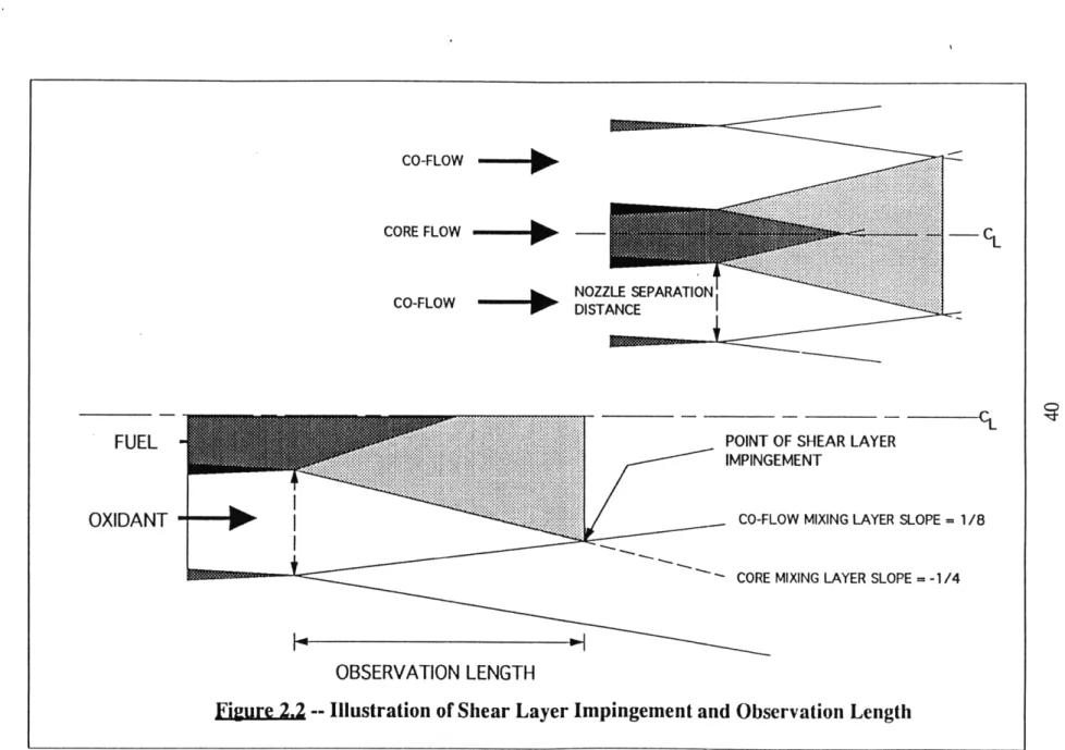
2.2.2c Observation Length
The term "observation length" refers to the flow area downstream of the lobed mixers before significant interaction of the flame with the air/air shear layer formed at the outer edge of the air co-flow, as illustrated in Figure 2.2. The shear layer growth from both the core nozzle and the co-flow nozzle must be considered.
From an experimental standpoint, an observation distance on the order of 15 lobe wavelengths is desirable (Ref. Figure 1.1), though a minimum of 8-10 wavelengths is
acceptable. The objective is to provide enough distance for the fuel/oxidant mixing process to occur before interference with the external air/air shear layer. As a result, the need for a minimum amount of observation length establishes a lower bound on core and co-flow nozzle exit diameters. This is demonstrated in the following
analysis. First, it was defined that a lobe wavelength is equivalent to 1/2 the core diameter. Next, it was assumed that the shear layer from the core nozzle grows in a 1:4 ratio, and that from the co-flow nozzle grows in a 1:8 ratio. Hence, the core "slope" was taken to be twice as steep as that of the co-flow. Accordingly, the
observation length requirement dictated a core and a co-flow diameter ratio of at least 1:5.5, to provide a minimum observation length of 12 wavelengths.
2.2.2d Boundary Layer Thickness
The presence of an inlet boundary layer, which is characterized by displacement thickness 8", affects the mixing augmentation potential of the lobed mixer. As the boundary layer thickness increases, low momentum fluid begins to fill the lobe. This boundary layer blockage effectively reduces the lobe penetration angle (Ref. Figure 1.1) seen by the fluid stream, thereby decreasing shed streamwise circulation and thence mixing enhancement. Therefore, the lobes must be designed such that the
boundary layers are thin with respect to the lobe wavelength X (Ref. 3.2.5). A "thin" boundary layer is considered to be one with a displacement thickness S which is less than five percent of the lobe wavelength X (O'Sullivan, 1993). This impacts the
selection of both X and flow velocity.
2.2.2e Fuel and Oxidant Flowrates
Fuel and oxidant flow in the combustor core and co-flow regions, respectively. The amount of mass flow available must be such that the individual and comparative
stream velocities may be varied over a wide enough range for sufficient experimental testing. However, fuel and diluent supplies are limited by gas cylinder size; the facility air supply sets the maximum air flow at 0.75 lbs/sec. The core and co-flow nozzle dimensions are thereby restricted, resulting from this competition between fluid supply and experimental flowrate demand.
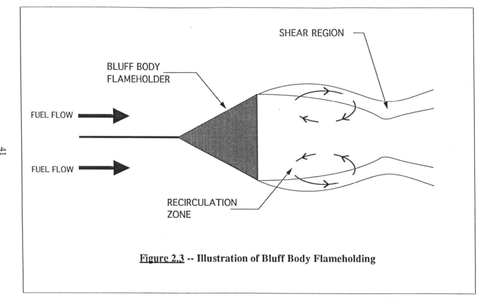
2.2.2f Flame Stability and Blowoff
The combustor in this experiment does not employ a flameholder other than the trailing edge of the lobe, in order to provide a flowfield affected only by the lobed configuration. Additionally, the observation length of the mixing region downstream of the lobes is limited and would be impaired by the presence of a flameholder.
The desire to achieve a stable flame which does not blow downstream is most typically fulfilled by a bluff body stabilizer, illustrated in Figure 2.3. A flameholder creates a region with a flow velocity which is less than the burning velocity of the mixture. The flame is stationary when the gas velocity equals its characteristic flame speed (burning velocity). The blowoff condition (for a specific stream temperature and mixture ratio) is approached as the gas velocity exceeds the flame speed.
edge and the downstream wakes are illustrated. Since the near-wake region velocity is less than that of the main flow, recirculation and shear layer formation is supported. Zukowski and Marble (1956) have proposed that the heat and mass transfer processes between the wake and shear layer regions are key in the flame stabilization
mechanism. The process description is as follows. The recirculation zone entrains hot combustion products which ignite the fresh mixture entering the shear layer. This
combusting mixture, as it flows downstream contained within the shear layer, in turn ignites fresh mixture. As the completely burned products leave the shear layer, some are recirculated into the wake region. Hence, a continuous source of ignition is established through-the shear layer and recirculation zones.
Furthermore, Zukowski and Marble theorize that blowoff (and eventual blowout) occurs when the fresh mixture does not remain in the shear layer sufficiently long to be ignited by the hot recirculation zone. Hence, the best flameholders are those which produce the longest residence times. Residence time may be represented by:
L
ZresidencU
wherein: L = recirculation zone length U = flow speed.
At blowoff, the flow speed is labelled as UBO . More precisely, the criterion for blowoff is when: residence chemical or L chemical UBO
Since L/U indicates the time the fresh mixture spends near the hot products, blowoff occurs when:
BO chemical L
hemical encompasses the chemical effects of the combusting flow, and therefore also
represents the ignition delay time. L represents the fluid mechanical effects. Hence, flameholder (and therefore wake) geometry is associated only with the fluid dynamics. The condition for flameholding is when:
reaidnce > t chemical
Recirculation length L is a function of both flow speed U, and flameholder trailing edge thickness 8, i.e.:
L=f (U, )
Additionally, since U and 5 are fixed, therefore L is a constant. Hence,
UBoch~m = contant
h~caI varies with fuel type. Based upon a personal communication with Waitz
(1994), it was assumed that:
1
chemicaldrogen 10 chemiclhydoar bo)
therefore
constant
1
constant
O oyen, 10 UBohydrbonFinally,
UBohydogen = 10( UBo n
)
Hence, the use of fuels with very short ignition delay times (most notably hydrogen) makes flameholding on a thin trailing edge possible. Specifically, this means that with an appropriately sized trailing edge and flow speeds, the core nozzle trailing edge thickness may function as a flameholding mechanism in this experiment without
additional support when hydrogen is utilized. Becker and Liang (1978) employed this hydrogen-stabilization method in their turbulent diffusion flame studies. For example, they were able to obtain a stabilized flame on a 0.030" trailing edge for a flow speed
of 82 m/s. Additionally, a "sharp-edged" nozzle trailing edge sufficed as the flame stabilizer in some of Hammer's turbulent flame work (1993).
Previous experimental findings concerning flame stabilization were examined in the context of this mixing research. First, stream-velocity-increase adversely affects flame stability. This results from a decreased residence time. Moreover, increasing turbulence intensity adversely affects flame stability. This is observed since
intensified turbulence entrains additional fresh material into the wake, thereby increasing the supply while decreasing available ignition time. Again, the upstream screens are of importance since they are utilized to control turbulence levels (Ref. 3.4).
2.2.2g Turbulent Flame
Practical combusting-flow applications which could benefit from lobed mixing technology, such as turbojet afterburners and also gas turbine and ramjet combustors, utilize turbulent flames. Hence, these experimental mixing studies should be geared toward turbulent flame use. A critical Reynolds number on the order of 3500 is used as the criterion for turbulent conditions. Based on the cold-flow jet diameter, the
Reynolds number is defined as:
Ud
Red--V
wherein: U = nozzle velocity d = exit diameter
v = fluid kinematic viscosity.
Figure 2.5 graphically presents this parameter as a function of mixture fuel composition for maximum speeds set by heat release restrictions.
2.2.2h Radiated Heat
The heat radiated from the combustion reaction region into its surrounding raises the test cell temperature. Consequently, the possibility exists for an unacceptable temperature rise wherein the test cell equipment and instrumentation would be adversely affected.
Ten percent of the heat generated was assumed to be radiated (Gore, et al., 1987) and a final test cell temperature of 120 degrees F was chosen as an acceptable
maximum value. However, it should be noted that this percentage is higher for hydrocarbon fuels -- 40% would be an approximate upper limit for hydrocarbon fuel heat radiation. Test cell temperatures, as a function of the hydrogen or ethylene composition of the fuel mixture, are depicted in Figure 2.4. The fuel mass flow rates incorporated into the construction of this figure were determined by the minimum fuel flow speed needed to reach the critical Reynolds number (Ref. 2.2.2h), assuming a 1" core diameter. These fuel flow speeds are therefore the minimum acceptable values for turbulent work. Minimum fuel flows correspond to minimum temperatures, which
are illustrated in Figure 2.4. Calculation of these temperatures proceeded as follows:
the heat radiated may be found by:
Q=hcAT
wherein the terms
(,c, A7)
refer to the mass flow rate, specific heat, and temperature change, respectively, for the air in the test-cell. Hence, the mass flow rate may be found by:
?flar =PV
wherein
N=(test-cell room volume)(number of room air changes unit time
The test-cell ventilation system provides 12 room air changes/hour.
Additionally, as referenced above, the heat radiated is assumed to be ten percent of the total heat generated, Qto, wherein:
and valve of the fuel.)LV = lower heating
Therefore,
Q= 10% of total
Calculation of the temperature rise of the test-cell proceeded in this way.
2.2.2i Flame Length
The test cell, with a floor-to-ceiling height of approximately 15', defines an upper bound for the flame length. Diffusion flame length is independent of the fuel velocity once the velocity required to attain turbulent conditions has been reached. In the laminar regime, the flame lengthens as the fuel velocity increases. Eventually, the speed is increased to the point wherein fuel and oxidant contact is enhanced by turbulent velocity fluctuations. This causes the flame to shorten (Figure 2.6). The flame length settles at a constant value (for a particular fuel composition) in the fully developed turbulent region. Hawthorne's equation for this asymptotic flame length is:
L 5.3 T
)
M+(1
/2D C, a)T Mn
where: L = flame length D = jet diameter
, = molecular weight of surrounding fluid M.= molecular weight of nozzle fluid
C, = mole fraction of nozzle fluid in unreacted stoichiometric mixture
at = moles of reactants/moles of products for
P
= 1 Tf = flame temperatureThe flame length dependence upon nozzle geometry and mixture composition, and independence of fuel jet speed is clear. It should be noted that the strength of this equation lies in its ability to provide a general sense of the flame length to be expected, for the given parameters. More detailed correlations are needed if higher degrees of accuracy are desired (Becker and Yamazaki, 1978). Figure 2.7 illustrates the flame length as a function of fuel-nitrogen composition for both hydrogen and ethylene with nozzle diameter set at 1" .
2.2.2j Momentum-Driven Flame
Buoyancy serves to increase the stream momentum, thereby increasing air
entrainment and decreasing diffusion flame length. In practical applications involving gas turbine engine combustion systems, buoyancy forces are small compared to momentum forces. Hence, a similar situation is desired in the current studies.
Buoyancy has also been shown to instigate turbulent flame stability problems (Becker and Liang, 1978). By affecting the flame large-scale structure, it causes lateral
oscillations.
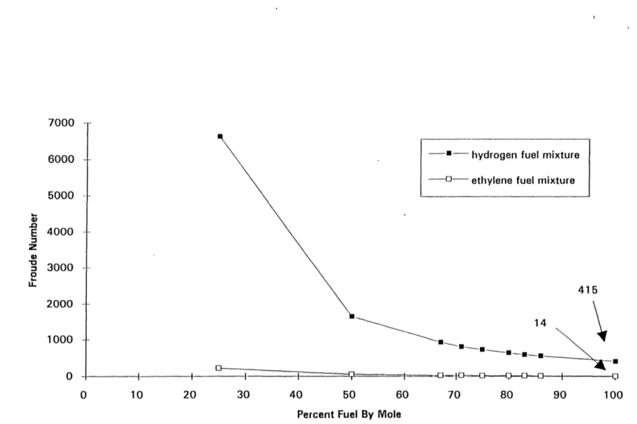
The Froude number relates momentum and buoyancy forces in a flow. It is defined as (Williams, 1985):
U2 Fr= u
gR
wherein: Fr = Froude Number U = nozzle exit velocity R = nozzle radius
Larger Froude numbers represent momentum-dominated cases. Flows with Froude numbers on the order of one hundred are acceptable for the present experiment. Figure 2.8 illustrates Froude numbers associated with possible testing conditions.
2.2.2k Flow Turbulence Control
A turbulence scale and intensity reduction mechanism is required in the burner design for the fuel and oxidant streams. The capacity for low inlet turbulence (i.e.:
u'/T < 0.01) is a requirement for some lobed mixer experiments. Likewise, the ability
to systematically vary the degree of upstream turbulence allows for examination of large-scale turbulence effects on mixing.
2.2.21 Nozzle Contraction
The decision to utilize a contraction configuration rather than a simple straight exit nozzle is governed by the physical aspects of the flowfield. The use of a contraction provides a more uniform and steady outlet stream than that produced with just a
straight section. The mean velocity increase allows for the use of lower velocities in the upstream region of the burner, thereby reducing pressure losses. Likewise, velocity variations are reduced to a smaller fraction of the average velocity, which is beneficial from a flow uniformity standpoint. Additionally, Qiu (1992) observed that accelerating streams through a 4:1 contraction nozzle reduces both boundary layer thickness and turbulence at the outlet. Hermanson also noted low turbulence and thin boundary layers with contraction usage, and recommended their use accordingly. Following the contraction ratios of 2:1 to 4:1 employed by Hermanson and Qiu, the nozzles were designed to have contraction ratios of: 2.7:1 for the co-flow, and 3.8:1 for the core.
2.2.2m Structural and Machining Requirements
Wall thickness and material selection must be sufficient to sustain and support the burner weight. Both choices must also withstand standard machining and welding processes.
2.2.3 The Flow Control System
2.2.3a Safety
The presence of an unconfined combustion reaction requires safety measures to be incorporated both in the fluid delivery system layout and in operational procedures. System purges are a necessity. Operator exposure to hazardous fuels or to the flame itself must be prevented.
The use of hydrogen gas in the facility presents the greatest potential hazard. This results from the inherent characteristics of hydrogen, the most relevant of which are listed below.
(1) gas undetectability -- colorless, odorless, undetectable by the five senses
(2) colorless flame with H2 and clean air combustion
(3) wide flammability limits with air -- in volume % of Hz, the lower/upper limits are 4.0/75. This represents the range over which ignition is possible when the gas is exposed to a sufficient energy source.
(4) explosion limits with air -- volume %, lower/upper, 18.3/59. Hence, Hz build up in the test cell must be prevented.
(5) ignition of H2-air mixtures at very low energy input -- 1.9x10⁸ BTU (.02 mJ)
@ 1 atm. To put this in perspective, this is only 1/10 that required for ignition of gasoline-air mixtures. Hence, any potential for sparks from the wiring must be eliminated.
(6) low viscosity and molecular weight -- since leakage is inversely proportional to viscosity, hydrogen systems are particularly susceptible to leakage problems.
Also, these characteristics account for the fact that the diffusion rate of H2 in air
is 3.8 times faster than air in air.
2.2.3b Flexibility and Control
In order to sufficiently explore lobed mixer phenomena, several flow parameters are required to be varied. Most important are:
(a) the ability to easily vary the proportion of fuel to diluent and their corresponding mass flows while a run is in progress
(b) the capacity to vary the air mass flow during testing
(c) the ability to change the type of working fuel or diluent.
Changing the fuel composition allows the amount of heat released to be varied. Control of the flow rates provides for examination of different velocity ratios between the co-flowing fuel and oxidant. Monitored regulation of the fuel, diluent, and oxidant is necessary to properly assess these effects on lobed mixing enhancement.
2.2.3c Exhaust Removal
A fume (exhaust) tube is required to provide for unburned (or partially burned) reactant and combustion product removal into the atmosphere. A fume tube also provides a means to contain the upper portion of the flame.
Consequently, design of the tube is governed by flame temperature and spreading angle. Spreading angle for a turbulent diffusion flame is approximately 20-25 degrees. The complexity of flame temperature calculations merits more sophisticated treatment.
Adiabatic flame temperature, simply put, is the final temperature of the products generated by an adiabatic combustion process (Heywood, 1988). The assumed
absence of heat and work transfer is validated by the fast time scales (~1 ms) on which combustion reactions occur. The resulting temperature, the adiabatic flame
temperature, is the maximum that may be attained for the given reactants. Any heat transfer or incomplete combustion would lower the product temperature. Hence, adiabatic flame temperature represents the "worst-case" of how hot the exhaust pipe could get. Therefore, if the material used to make the fume tube is rated to withstand temperatures near or above that of the adiabatic flame temperature, the material is suitable. To calculate these temperatures for mixtures specific to the present research, a thermodynamic computer code, STANJAN, was employed. Developed by Prof. Reynolds of Stanford University, it has been widely used for several years. The reactions used in these adiabatic flame temperature calculations are:
Hydrogen-Air:
Ethylene-Air:
C2H, +3 (02 +3.78N2)
-aCO2+bH20O+cO2+dH2+eN2 +fCO+gC +hCH4+iOH+jH+kO+lNO+mNO2+nC2H4
The results are plotted in Figure 2.10 for hydrogen-air and ethylene-air combustion. For both cases the maximum flame temperatures occurs at slightly fuel-rich conditions; hydrogen-air combustion peaks at approximately 2340 K, and ethylene-air peaks at
2390 K.
An exhaust tube previously designed for industrial use was installed in the test cell facility. Its generous size (36" diameter) easily handles the flame spreading angle criterion. However, its operational upper limit of temperature is 3000 degrees F, or
1922 K, which is less than that of the predicted maximum flame temperatures. However, the fume tube material limits are still well within an appropriately safe temperature range for two reasons. First, the adiabatic flame temperature represents an
absolute maximum of the temperature that the fume tube could be exposed to. Second, the entrainment phenomenon dilutes the reaction flowfield, thereby lowering the temperature. For a fuel jet exiting from a circular duct, the mass entrained, m, may be represented by:
m
x
m =0.32 1
mo
do po
where: mr = injected mass
po = injected mass density
p: = ambient density
do = duct diameter
The heat sink of the entrained mass was accounted for in determining the suitability of the industrial exhaust tube.
2.2.4 Evaluation
From the aforementioned criteria (Refs. 2.2.1 to 2.2.3), the boundaries of
experimentally applicable and attainable test-run flow conditions may be established.
The evaluation begins with the combustor's geometric constraints. Namely, the core and co-flow nozzles must have a 1:5.5 outlet diameter ratio to produce an
"observation length" sufficient to examine the mixing process. Observation lengths for various core/co-flow nozzle diameter combinations are illustrated in Figure 2.11. The requirement for thin boundary layers on the lobes and fuel and oxidant flow rate limitations (Ref. 4.1) placed respective lower and upper bounds on the nozzle
dimensions. The result is the selection of a core nozzle with an 1" outlet diameter and a co-flow nozzle with a 5.5" outlet diameter.
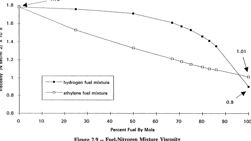
Appropriate mixture compositions and flow rates may now be determined. At this juncture it is appropriate to highlight the fact that many of the parameters under
consideration are dependent upon fuel properties. For example, flame length is a function of fuel molecular weight; likewise, Reynolds number relies upon the core mixture density and viscosity. These property values change as either the hydrogen or the ethylene fuels are diluted with nitrogen. This effect, demonstrated in Figure 2.9, was incorporated into the calculations.
The radiated heat calculations indicate that the use of pure hydrogen creates an unacceptable test cell temperature rise. Mixtures with compositions of 86% hydrogen and 14% nitrogen (6:1) or more dilute, however, are within the specified range. Pure ethylene (and hence any diluted mixture composition) is acceptable.
Likewise, flame length considerations put constraints on fuel mixture composition. As indicated in Figure 2.7, the flame heights generated from all hydrogen-nitrogen compositions may be accommodated. However, the fact that the length drops from 8' to 5' at the 10% diluted case makes the dilution alternative an attractive one. Ethylene produces a much longer flame length. Hence, a fuel composition of ethylene diluted with nitrogen is necessitated.
It is important to note that though both the radiated heat and flame length criteria encourage the use of fuel dilution with nitrogen, flame stability concerns prevent excess. The more diluted the fuel, the less stable is the diffusion flame.
The desire to have a turbulent flame, sets the acceptable lower bounds for fuel flow speeds, provided in Figures 2.12 and 2.13, found through corresponding Reynolds number calculations. Each mixture composition has a particular minimum value. The situation for the momentum-driven flame criterion is similar. Obtainment of a Froude number on the order of one hundred places a lower bound on flow speed for each mixture composition.
The maximum flow speeds allowable are established by the radiated heat criterion, since the amount radiated is proportional to fuel mass flow rate (Ref. 2.2.2g). The maximum flow speeds for varying mixture composition are presented for both the hydrogen and ethylene cases in Figures 2.12 and 2.13, respectively. Again, the flame stability and blowoff issues (Ref. 2.2.2f) could play roles in limiting the usefulness of high flow speeds.
2.2.4a Test-Run Quantities
Each criterion discussed places limitations on the range of test-run quantities applicable to this experiment. This analysis was performed to provide a sense of where in the "parametric space" of flow and composition variables this research could
be most usefully carried out. However, it should be noted that though these results provide a reasonable reference, actual experimental conditions may allow for the
crossing of the test-run "boundaries." Tables 2.1 and 2.2 present the flow parameter ranges for hydrogen and ethylene fuels, respectively.
S-I - -I I
79" 40" 79" 40"
CO-FLOW
CORE FLOW - h
CO-FLOW - P
- C
~r~Lcc
POINT OF SHEAR LAYER
IMPINGEMENT
CO-FLOW MIXING LAYER SLOPE = 1/8
CORE MIXING LAYER SLOPE = -1/4
OBSERVATION LENGTH
Figure 2.2 -- Illustration of Shear Layer Impingement and Observation Length FUEL
OXIDANT
SHEAR
REGION
BLUFF BODY
FLAMEHOLDER
FUEL FLOW -I FUEL FLOWRECIRCULATION
ZONE
L
ir minimum acceptable Re #3500
- hydrogen fuel mixture
_-- ethylene fuel mixture
Turbulent Regime
Laminar Regime
10 20 30 40 60 70 80 90 100
Percent Fuel By Mole
Figure 2.4 -- Maximum Reynolds Numbers For Fuel-Nitrogen Mixtures
40000 35000 30000 25000 20000 15000 10000 5000 t---~---l
80
60
10 20 30 40 50 60 70 80
Percent Fuel By Mole
Figure 2.5
--90 100
Temperatures Resulting From Radiated Heat
[fuel flow rate is that required to get Rec,,,,, = 3500]
120 F; maximum acceptable temperature - hydrogen *- ethylene 180 160 140 120 100 LL +. o E
I-Laminar
region
Transition Fully developed region I turbulent region
Jet velocity
Figure 2.6 -- Diffusion Flame Length Variation With Fuel Jet Velocity [Reference: Flagan and Seinfeld, 1988]
u - __18.1
18 -- - hydrogen fuel mixture
1 6 - - - ethylene fuel mixture
14 -- 12 c 10 8.2' _J S E 8 64 -0 I II I 0 10 20 30 40 50 60 70 80 90 100
Percent Fuel By Mole
Figure 2.7 -- Flame Lengths From Fuel-Nitrogen Mixtures [for jet diameter = 1"]
7000 6000 5000 4000 3000 2000 1000 0 t---a-l3--c-p; r;o I 30 40 60 70 80 90 100
Percent Fuel By Mole
Figure 2.8 -- Maximum Froude Numbers For Fuel-Nitrogen Mixtures
415 14 ~ --_ _U Ip! • * I I !
1.78 1.6 mU LO <1.01 E z
o -"- hydrogen fuel mixture
u
0.8 - -- ethylene fuel mixture
0.9 0.6
0 10 20 30 40 50 60 70 80 90 100
Percent Fuel By Mole
2500 o 0 2 2000 - 0 U 0 2000 0
a
1500 EI--E
., 1000 U hydrogen fuel a, 500 - ethylene fuel 0 I I I I 0 0.5 1 1.5 2 2.5 3 Equivalence Ratio14 12 10 8-6 0 0.75 1 1.25 1.5 1.75 2
Core Diameter (inches)
Figure 2.11 -- Observation Lengths For Various Core/Co-Flow Nozzle Diameter
30
-*- minimum set by Reynolds #
25
25 maximum set by temp. limit
20 E : 15 a 8.3 0 I I I 0 10 20 30 40 50 60 70 80 90 100
Percent Hydrogen By Mole
5 minimum set by Reynolds #
Smaximum
set by temp. limit4 E 4) 3 0. U) 1 1.31 I1 --- _ il 1.21 0 I I I I I I I I 0 10 20 30 40 50 60 70 80 90 100
Percent Ethylene By Mole
Table 2.1
--
Principal Operational Quantities Utilizing Hydrogen Fuel
GEOMETRY core diameter: 1" co-flow diameter: 5.5" H,-N, MIXTURE DATA molar composition: 86% H2 50% H2mixture flow speed: 14.4 m/s
3.8 m/s
(= 6:1, H2:N2) (=
1:1,
H2:N2)maximum
minimum
mixture mass flow rate: 4.47x10³ kg/s 9.84x10⁴ kg/s
hydrogen mass flow rate: 3.00x10⁴ kg/s 8.02x10- kg/s maximum minimum maximum minimum maximum minimum
Table
2.2 --
Principal Operational Quantities Utilizing Ethylene Fuel
GEOMETRY core diameter: 1" co-flow diameter: C,H7-N MIXTURE DATA molar composition:mixture flow speed: 2.6 m/s
100% C2H4
50% CH4 (= 1:1, C2H4 : N2)
maximum
1.2 m/s minimum
mixture mass flow rate: 1.52x10³ kg/s 7.61x10⁴ kg/s
ethylene mass flow rate: 7.61x10⁴ kg/s 4.63x10 s kg/s maximum minimum maximum minimum 5.5" maximum minimum
CHAPTER 3: FACILITY DESCRIPTION AND
OPERATION
3.1 Results of the Design Procedure
The requirements and constraints associated with the facility as a whole, as well as those relating specifically to the burner and flow control system, were discussed in Chapter Two. The present chapter presents and explains the design choices made in light of these restrictions. Facility operation, also affected by these requirements, is presented as well.
3.2 The Burner Design
3.2.1 Physical Description of the Co-Annular Burner
The vertically standing burner is 38" high, with a 10" maximum outer diameter. Its overall design, composed of a honeycomb, flow screens, and nozzles, is shown in Figure 3.1. The air is piped through a 1" diameter inlet located at the base of the burner. The co-flowing air stream enters a 12" high, 9.25" diameter plenum chamber, which contains a flow straightening honeycomb located after the air inlet (Ref. 3.2.3). The honeycomb cell diameter is 0.125". If desired, it is possible to change the honeycomb geometry. This is possible because the honeycomb is attached to the combustor interior by set screws, rather than by welding, and also because of the removability of the burner base. At the end of the plenum, the air is directed into the co-flow chamber by the parabollically shaped nose cone attached on the core tube base. The nose cone serves to minimize the pressure loss that the air flow experiences when it encounters the core chamber bottom. The hydrogen fuel (which may be diluted with nitrogen) enters the burner core, having been supplied from the side of the combustor. As the fuel and air flow in their respective chambers towards the nozzle exits, they encounter turbulence-reducing flow screens. Since it was desirable to be
able to vary the turbulence level of the flowfield, the burner is equipped with "screen spacers." These allow both the screen types and locations to be easily changed.
Finally, the core flow and co-flow enter the nozzles from which they exit the burner and, thereupon, are ignited. The co-flow nozzle has a 2.7:1 contraction ratio, while the core has a 3.8:1 contraction ratio. The co-flow nozzle contracts the airflow from a 9" chamber diameter to a 5.5" exit diameter. The core nozzle contracts the
flow from a 1.96" core-chamber diameter to a 1" exit diameter. These nozzles are removable. Their removal provides access to the screen spacers and the flow screens themselves, and the interchangability of the core nozzle allows either splitter or lobe configurations to be used, providing for mixing enhancement control. Additionally, the contraction ratios of both the core and co-flow nozzles may be changed if needed.
Further illustrations of the combustor components may be found in Appendix A.
3.2.2 Burner Structure
The overall structure of the burner may be treated in four lengthwise segments: first, burner base to honeycomb; second, honeycomb to core base; third, core base to nozzle base; and fourth, nozzle base to burner exit.
The 3" long base-to-honeycomb section provides a space for the inlet air flow to attain some flow static pressure and angle uniformity before reaching the honeycomb. This length is three times larger than the diameter of the air inlet -- a standard
recommendation to maximize benefits from the honeycomb. The second burner segment provides a 9" length for the post-honeycomb turbulence to dampen and the flow to straighten. This section is 36 honeycomb cell diameters long -- appropriate dimensioning for this dual purpose. The 18" length of the third section (i.e. the core flow and co-flow chambers) supplies the area in which flow turbulence levels are dictated, through the use of flow screens. Material cost and weight restricted the
length of this segment. The discussion of the fourth segment, which consists of the nozzles, is delayed until Section 3.2.5.
The selected burner diameter dimensions meet several design requirements. It was desired to have as large an inlet plenum chamber as possible (i.e. segments 2 and 3 described above), with limitations set by the cost and weight of the pipe used in construction. The amount of air mass flow available was also of concern (Ref. Chapter 2). Additionally, a sufficient co-flow nozzle contraction ratio was required (Ref. Section 2.2.21), which also impacts the chamber diameter dimension. Likewise, the core-flow-nozzle contraction ratio set the core-chamber diameter. These
constraints result in a plenum chamber inner diameter (ID) of 9.25", a co-flow chamber ID of 9", and a core-flow chamber ID of 1.96".
The minimum allowable plenum chamber outer diameter (e.g. wall thickness) was set by support requirements. The 0.375" wall thickness selected is more than
sufficient to sustain and support the 130 lb. burner. The carbon steels used in the construction of core flow and co-flow chambers and nozzles, as well as the low flow speed used in the experiments (Ref. Chapter 2), sufficiently alleviate concerns about hoop stress and wall deformation. The wall thicknesses, indicated in Figures 3.3, A.1,
and A.2, were therefore established by machining requirements, product availability, and cost.
3.2.3 The Honeycomb
A honeycomb was employed to reduce swirl and turbulence levels. Undesirable
characteristics associated with honeycomb usage involve "cell stall" and small-scale turbulence shedding. Cell-stall and its corresponding pressure loss occurs with large flow yaw angles (Mehta and Bradshaw, 1979). To help alleviate this affect, the honeycomb was installed 3" downstream from the air inlet, in order to provide the air flow with space to partially straighten.
As for honeycomb construction, it has been shown (Mehta and Bradshaw, 1979) that honeycomb cell length should be 6-8 times the cell diameter for optimum benefit. The dimensions present in the combustor are 0.125" cell size and 0.25" cell length, in accordance with this design specification.
3.2.4 Flow Screens
The flow screens used in this research are constructed of 308 stainless steel wire interwoven into a square mesh. Flow screens were incorporated into the co-annular combustor design as turbulence scale and intensity reduction mechanisms. Upstream turbulence may be controlled by changing the screen mesh and placement.
Screen performance is typically described by two parameters: the pressure drop coefficient K and the deflection coefficient a. Both are functions of the flow
incidence angle 0 and the screen open area ratio (i.e. porosity) [3. Since the screens see perpendicularly oncoming flow, a is of little significance in this experiment.
The values for the screening used in these specific experiments are listed in Table 3.1; the justification of their selection follows.
Flow screens are used with the objective of obtaining a uniform velocity profile. This is achieved by imposing a static pressure drop (which is proportional to the
upstream speed squared). The flow characteristics in the immediate downstream vicinity are significantly different from the rest of the flow field. Most importantly,
this particular region contains small scale turbulence of substantially higher levels than that of the unmanipulated flow. This, as explained by Laws and Livesey (1978), is the resulting combination of three separate turbulence profiles due to: screen generated turbulence, the passage of upstream turbulence through the screen, and shear generated turbulence produced by the wire wakes. This phenomenon motivated the selection of 18" high core and co-flow chambers. This allows for the use of several screens in the
chambers with enough space provided for each turbulence decay region (15 - 25 mesh widths). Within this region, recovery from the static pressure perturbation and
turbulence increase occurs. The upper bound on the chambers' heights was dictated by cost and by a desire to prevent unnecessary boundary layer growth within the core and co-flow areas.
Care was also taken to avoid the onset of jet coalescence. This phenomenon results in the production of trailing vortices in the downstream flow, introducing non-negligible effects on the flow characteristics. Jet coalescence prevention is twofold. First, only screen porosities less than 0.57 should be used (Laws and Livesey, 1978). This in turn implies a resistance coefficient K of less than 2.8 for uniformity. From this, the second preventive measure arises -- the use of multiple screens to obtain a particular pressure drop.
It has been shown (Groth and Johansson, 1988) that maximum turbulence reduction for a given total-pressure drop occurs with the use of cascaded screen combinations, the coarsest screen being upstream. This may also be discussed in terms of another parameter -- Re.,, wherein:
e Ud
Values of Re,,,, above 40 are considered supercritical: below, subcritical.
Combinations of supercritical screens provide more turbulence suppression with less pressure drop penalty (AP3t). Values in the context of this experiment are:
for upstream screen, with wire diameter = 0.254 mm: Re,,, = 44

![Figure 2.6 -- Diffusion Flame Length Variation With Fuel Jet Velocity [Reference: Flagan and Seinfeld, 1988]](https://thumb-eu.123doks.com/thumbv2/123doknet/14681750.559417/44.918.300.640.191.581/figure-diffusion-length-variation-velocity-reference-flagan-seinfeld.webp)
![Figure 2.7 -- Flame Lengths From Fuel-Nitrogen Mixtures [for jet diameter = 1"]](https://thumb-eu.123doks.com/thumbv2/123doknet/14681750.559417/45.1188.106.1061.170.642/figure-flame-lengths-from-fuel-nitrogen-mixtures-diameter.webp)