Design and Implementation of a
Solar Power System in Rural Haiti
by
Shaheer M. Hussam
Submitted to the Department of Mechanical Engineering in Partial Fulfillment of the Requirements for the Degree of
Bachelors of Science in Mechanical Engineering at the
MASSACHUSETTS INSTITUTE OF TECHNOLOGY February 2004
© MMIV Shaheer M. Hussam. All rights reserved. The author hereby grants to MIT permission to reproduce
and distribute publicly paper and electronic copies of this thesis document in whole or in part.
Author - .- -- -
--Department of Mechanical Engineering
-<,~~
,~~~
A)
January23, 2004
Certified by
I
Stephen ConnorsTheSis Supervisor, Laboratory for Energy and the Environment
Accepted by _I_ _
Ernest Cravalho Chairman, Undergraduate Thesis Committee
ARCHIVES
MASSACHUSETTS INSTITtE OF TECHNOLOGY
Design and Implementation of a
Solar Power System in Rural Haiti
by
Shaheer M. Hussam
Submitted to the Department of Mechanical Engineering on January 23, 2004 in Partial Fulfillment
of the Requirements for the Degree of Bachelors of Science in Mechanical Engineering
ABSTRACT
This paper describes the design and implementation of a solar power system for a school and health center in Petit-Anse, Haiti. The end-use applications are lighting via a set of fluorescent and incandescent bulbs, and a coolbox for medical refrigeration at the health center. The power is derived from five 120W photovoltaic BP Solar panel units. The author and colleagues traveled to Petit-Anse in January 2002, and a final implementation plan for the Spring of 2004, describing budget, team development, and itinerary is described.
Thesis Supervisor: Stephen Connors
Title: Director, Analysis Group for Regional Electricity Alternatives at the Laboratory for Energy and the Environment
ACKNOWLEDGEMENTS
The author would like to thank the teachers and students of Development Lab/The Haiti Class (SP.712) for their impressive work in initiating, designing, and operating the course. Special thanks goes first to Amy Smith '84 and Jamy Drouillard G, for being the teachers when I took the course, and the initial team members: Johanne Blain G and John Pope '03. And a thanks to all the other students in SP.712 for their enthusiastic work for such an important class at MIT.
Further thanks goes to Stephen Connors, for his patience in guiding this thesis and his knowledge on a variety of fascinating energy issues. Thanks also goes to Ed Moriarty for his help on various thesis issues and in connecting the project with his work at the O'Bryant School. Many thanks to the BP Solar folks who donated their time and resources in getting our team the solar panels. This project would not have been realistic without their help.
Finally, great thanks to everyone in Boston and Petit-Anse that made this project feasible and worthwhile - Gerty Lahens, Father Valcimond at the monastery, and all our colleagues of the Friends of Petit-Anse cooperative.
TABLE OF CONTENTS
List of Figures 5 1. Introduction...6 1.1 Technical Summary 6 1.2 Community Overview 6 1.3 Client Summary 7 1.4 Our Involvement 8 2. System Components ... 10 2.1 PV Modules 10 2.2 Charge controller 11 2.3 Batteries 132.5 Balance of System (BOS) 13
3. System Design ... 13 3.1 Client Needs 14 3.2 Project Constraints 15 3.3 Load Calculation 15 3.4 Array Sizing 16 3.5 Battery Sizing 17 3.6 Balance of System 17 3.6.1 Panel Mounts 18 3.6.2 Wiring 18 3.6.3 Equipment Housing 18 4. System Implementation ... 20
4.1 Funding and Project Costs 20
4.1.1 Funding 20
4.1.2 System Costs 20
4.1.3 Field Costs 21
4.2 Component Acquisition and Transportation 21
4.3 Team Development 21
4.4 Travel Itinerary 22
4.5 Work Ahead and Concluding Remarks 22
5. References ... 24 6. Appendix ... 25
6.1 BP Solar 120S product specifications 25
LIST OF FIGURES
Introduction Page 1.1 Map of Haiti 7 1.2 General Photos 8 1.3 Roof/Site Photos 9 1.4 Layout of Site 10 System Components 2.1 BP Solar 120S Panel 11 2.2 Lighting 12 2.3 Coolbox 12 2.4 Charge Controller 13 System Design 3.1 Block Diagram 14 3.2 Client Requirements 14 3.3 Project Constraints 15 3.4 Load Estimation 16 3.5 PV Array Sizing 16 3.6 Solaration Map 173.6 Battery Array Sizing 17
3.7 Wiring 19
Project Implementation
4.1 System Costs 21 4.2 Field Costs 21
1.
INTRODUCTION
What are the possible technologies for producing off-grid electricity in developing
countries? Options include fossil fuel-based technologies such as diesel generators, or renewable sources such as photovoltaic or wind power.
In this thesis, I describe the design and implementation of a photovoltaic (PV) electric power system in the village of Petit-Anse in rural Haiti. The system provides 600W of DC power for lighting and refrigeration at a school and health center.
In the following sections we will give a brief overview of the technical elements of the
project, as well as an overview of the local community and local partnerships.
1.1 Technical Overview
The system provides year-round electricity for lighting and refrigeration. The power is derived from five 120W BP Solar panels [ ] and delivered via a charge controller to a set of deep-cycle batteries, which ultimately deliver power to the lighting elements and a coolbox.
The panels will be placed flat on the roof of the health center, with batteries, charge controller, and housing inside one corner of the center. Wiring will run into the school, which is adjacent to the center, and provide overhead lighting. The specific location of the coolbox and health center lighting will be determined upon arrival on-site.
1.2 Community Overview
The school and health center are located in the small fishing village of Petit-Anse. [pe-EET ANse], near the northern city of Cap-Haitien [cup AY-ee-SEE-en]. Cap-Haitien is also
CUBA le de a To, -sr',;,t. N.pg,-," f-.- -- Por-lde-Pa* -! lie de la Gonave - J6remie POR ... I. -.:: POR Miragoane Les Cayest --. rtue Cap-Ha tier? '- :'-'- : Gona'ives Saint- '--.Marc Hn X%
Hispaniola
T-AU-PRINCEg Jacmel DOMINICAN' ' REPUBLIC i t5 t, In S e 'ho 0 30 0 kmFIG 1.1 Map of Haiti. Petit-Anse is adjacent to the northern city of Cap-Haitien [2].
Cap-Haitien is capital of the Nord Department, on the Manzanillo Bay, an inlet of the Atlantic Ocean. Cap-Haitien has a large harbor and is an export center for coffee, cocoa, hides, honey, and wood. The estimated population for Cap-Haitien is around 70,000, while for
Petit-Anse it is around 7,000 [3].
Fishing is the primary source of commerce in Petit-Anse. One of the problems in the area results from the soil erosion caused by extensive deforestation in Haiti. The water immediately surrounding the island has been contaminated and the good fishing stock to shrink and to be pushed further from the shore. This has put additional pressures on the population of Petit-Anse.
1.3 Client Summary
Our client is the Friends of Petit-Anse (FPA), an organization formed by villagers living in Petit-Anse, and co-sponsored by the non-profit Saint Boniface Foundation of Boston,
Massachusetts.
Friends of Petite-Anse came into existence in the summer of 2000. The organization founded a school for the youth in the village that is designed to offer both fishing vocational training and general education. Friends of Petite-Anse has also established a fishing cooperative that is run by the villagers.
The school affiliated with the organization currently educates approximately 80 students ages six to eighteen. The students spend half of each day in the classroom on academics, with the
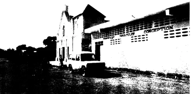
other half spent on vocational fishing education. The FPA has also built a building that will serve, among other purposes, as a health center.
FIG 1.2a From left to right, the Petit-Anse church, school, and health center complex
I
~..~
FIG 1.2b,c (b) Photos of the building exterior and students, (c) Photo of the interior of the health center and various
members of the FPA fisherman's cooperative.
1.4 Our Involvement
The project was chosen after an IAP 2002 (January term) trip to Haiti through the MIT course "The Haiti Class" (SP.712). The course was run in both the Fall and Spring terms of the 2002-2003 academic year. The Haiti Class was developed through the efforts of Amy Smith of the Edgerton Center and the MIT Haitian Alliance. (After the successful work of the first year, the course expanded to include Brazil and India and has been renamed Development Lab, or "D-Lab"). Course members established partnerships with Haitian NGO's and Peace Corps workers, who assisted us during our work.
VW
0- T
-1
Course members, including the author, traveled to Haiti in January 2002 to assess various field sites for potential engineering projects. Through FPA, we were able to visit sites around Petit-Anse and develop various project plans. The school and health center were visited, and we were thus able to assess their electrification needs.
The volunteers of the FPA cooperative assisted the team in touring Petit-Anse, and helped provide lodging during our stay. During the return trip we anticipate further assistance as well.
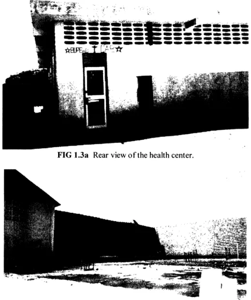
During the trip, photographs and diagrams were made of the school/health center
complex. Photographs of the interior, roofs, and general surroundings were taken. These were later utilized in the design phase of the project.
$ ~ ~ - .- ; ,
-, ~~ ~ ,, - -? m w ~ m- - - - -
-Om no *mmm a am Om mm W mmmm
_ _
FIG 1.3a Rear view of the health center.
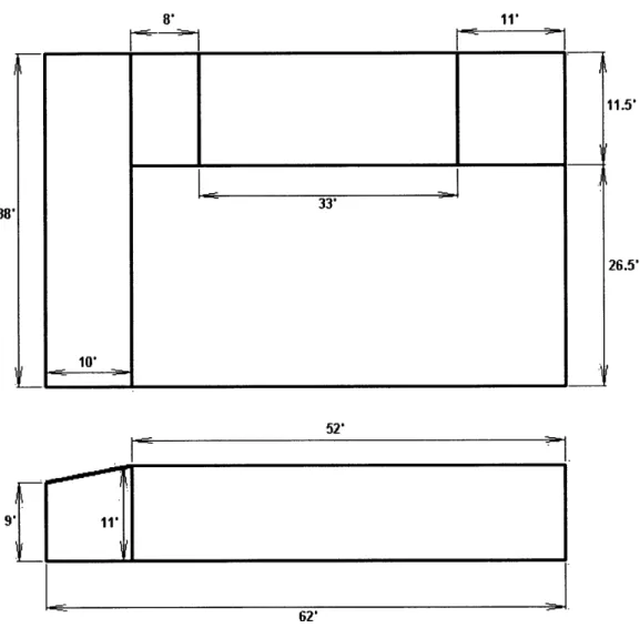
38' 11' ---.. 52' 11.5' 26.5' 62'
FIG 1.4 Site Layout. Top view is an overhead of the school (on the left) and the health center. Bottom view is a profile.
2.
SYSTEM COMPONENTS
In this chapter we will give a technical overview of the system components. The sections are (1) photovoltaic solar panels, (2) end-use applications, (3) charge controller, (4) batteries, and (5) other balance of system (BOS) components. In the subsequent section (Chapter 3, System Design) we will discuss the overall design.
2.1 Solar Panels
The system utilizes five 120W panels manufactured by BP (British Petroleum) Solar [I]. The panels were off-spec, functional units donated by their chief US production facility in Frederick, Maryland (former headquarters of Solarex International).
33' 10 -9g
Each panel measures 28.3 lbs and is 57.3" x 28.8" x 1.97" in volume. Each panel is
composed of 72 multicrystalline silicon cells, wired as 2-series strings with bypass diodes across each 18-cell segment. The cell layer is laminated between sheets of EVA (ethylene vinyl acetate) and high-transmissivity 3mm tempered glass. The multicrystalline panels typically operate at about
13%-15% efficiency.
FIG 2.1 Front view of the multicrystalline BP 120S panel. See Appendix 6.1 for detailed product specs.
With the assistance of Steven Fernandes and his physics students at O'Bryant Secondary School, it was found that four of the five panels were on spec for short-circuit current (c) and open-circuit voltage (Voc), at around 7.7 amps and 21 V, respectively. The fifth panel still needs to be tested.
2.2 End-Use: Lighting and Refrigeration
2.2.1 Lighting
We decided to mix use of incandescent and fluorescent bulbs, since both were available in Cap-Haitien. The fluorescent bulbs offered more efficient lighting, whereas the incandescent bulbs were more easily and cheaply available. The system was designed for six 40W fluorescent bulbs and four 60W incandescent bulbs, which will be purchased on-site in Cap-Haitien.
This specific light fixtures to be used will be purchased at MIT. The fluorescent bulbs will be used exclusively in school lighting and will use standard ceiling fixtures. The lamps used in the examination area at the health center will be purchased beforehand at MIT.
FIG.2.2 Circline fluorescent [4] and incandescent bulbs [5]. 2.2.2 Refrigeration
The refrigeration component is a commercially-available coolbox. We used a
"thermoelectric travel cooler/warmer" from Vector Manufacturing. The coolbox uses a 12 V DC input and draws a continuous 36 watts.
FIG 2.3 Thermoelectric Coolbox [6].
2.3 Charge Controller
A charge controller is necessary to optimize battery power usage for the system. At the minimum, charge controllers prevent the battery bank from overcharging. As of this date a charge controller adequate for on-site implementation had not been purchased. We describe below a possible charge controller for small-medium sized PV systems.
The charge controller will be rated at between 35 and 40 amps. Prices in this range go from $100-$150. This system is at 35.7 amps, so we will look at a 35amp system. One potential controller is the Trace C35 from Xantrex Technology, priced near $110.00 [7]. The unit weight
is at 2.7 lb, and unit dimensions are 8.0" x 5.0" x 2.5" (3.0 lb and 12.4" x 7" x 2.5" for shipping
weight and dimensions).
1117 3A, _- _,,Yil_-, 1IF ,F
FIG 2.4 Trace C35 from Xantrex Technology [8].
2.4 Batteries
Batteries store electrical energy, enabling continual delivery of PV power at night or on cloudy days. The batteries used in PV systems are typically deep-cycle (lead-acid) batteries in the 100-300 amp-hour range.
This system was designed to use two 225 V batteries in parallel. According to our contacts in Haiti and our experience in the field, we anticipate purchasing the batteries from the main city area in Cap-Haitien. This will also save time/costs in transporting the batteries.
2.5 Balance of System (BOS) Equipment
Balance of System (BOS) equipment integrate the structural and electrical components of the system with the field site. In addition to the batteries, charge controller, BOS equipment includes wiring, component housing, and the PV panel mounts.
Further work is needed to determine the final design and construction of the BOS components. The wiring will be purchased at MIT and the housing/mounts will be designed and made on-site in Haiti. The construction of the housing and mounts will depend on additional data and analysis of the site, and will be undertaken in the field.
3.
SYSTEM DESIGN
In this section I will describe the overall design of the project. We will describe the client needs, project constraints, system sizing, and system integration with the site. The general integrated design process was as follows:
i. Assessment of client needs (end-use applications, fixed costs) and project constraints (budget, material availability)
ii. System Design / Sizing (Determination of load, PV array, battery array) iii. System Integration (Panel roof mounts, lighting/coolbox placement, wiring)
Each step of the process was interrelated, and feedback occurred throughout between the client, team members, and the author.
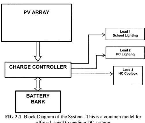
Below we show a general block diagram of the system and later we will show the wiring diagram. The block diagram is a typical setup for off-grid, DC, low-wattage systems. The wiring diagram and sizing tables will be provided later in the section.
FIG 3.1 Block Diagram of the System. This is a common model for off-grid, small to medium DC systems
3.1 Client Requirements
The general client requirement was to deliver cheap power for the users of the school and health center in Petit-Anse. The system would have to be zero initial cost and low fixed costs. It should be easy to maintain and reliable.
The school provides after hours vocational and elementary education. Lighting needs for after hours teaching is approximately 3 hours per day for 6 days a week. The coolbox needs nonstop power, 7 days a week.
Client Requirements: Evening Lighting
Continuous Refrigeration No Initial Cost
Low Fixed Costs Low Maintenance
FIG 3.2 Summary of Client Requirements
In return, the client agreed to offer extensive logistic support during the initial and planned
3.2 Project Constraints
Minimizing costs and maximizing simplicity was similarly the chief concern throughout the design process. Due to these constraints and user feedback, it was decided early to limit the initial project scope to lighting and medicine refrigeration.
Since the site was located off-grid, to minimize cost and inefficiency the system was designed as a DC system. Although an AC system would have allowed for grid connectability and more variety of end-use applications, it would have required an DC/AC inverter, increasing the power inefficiency and component acquisition/ transportation costs.
Project Constraints: Low budget Simple
Easily transportable Limited time frame
FIG 3.3 Summary of Project Constraints
3.3 Load Calculation
The load calculation was done in two iterations. The first iteration was a rough load estimate to determine the minimum PV amperage needed to complete the project, so that donations of PV panels could be sought. The second iteration was a more detailed calculation done after the panels had been acquired and tested.
Given the assumptions of a DC, low-cost system, the initial goal was to determine the loads on the system. The first load element was the refrigeration, and the second element was the
building lighting.
For the refrigeration component, a product survey suggested that a 50W DC component could be purchased. Based on-site experience and site measurements, we assumed lighting by fluorescent bulbs and a minimum of eight bulbs necessary for sufficient lighting of the school and health center.
For the second iteration, we chose and purchased the refrigeration component and constructed a more diverse lighting load profile.
The optimal refrigeration component was found to be a commercially-available Peltier coolbox. We purchased a "Thermoelectric travel cooler/warmer" from Vector Manufacturing. The coolbox used a 12V DC input and drew continuous 36 Watts.
Several types of lighting were used. We decided on a combination of incandescent and fluorescent, with the option for later use of LED components. Incandescent bulbs were chosen as the dominant form of lighting for their availability in the region and low-cost. Fluorescent were
chosen for their higher efficiency and longer life-span.
DC Load Units W/Unit Total W HrslDay Days/Wk Hrs/Wk W-Hrs/Wk
Coolbox 1 36 36 24 7 168 6,048
Fluorescent 6 40 240 3 6 18 4,320
Incandescent 4 60 240 3 6 18 4,320
14,688 FIG 3.4 Load Calculation
In this figure we see the general load profile of the system. The daily and weekly loads reflect the client requirements discussed in Section 3.1. The wattage values were obtained from system component specs discussed in Section 2.2. The average amp-hours required per day was obtained by dividing watt-hours/wk by 12V DC by 7 days). This resulted in a total of about 175 amp-hrs/day. In the following section, we see how the PV array sizing was done to show that the five 120W 7.0 peak amp panels obtained were sufficient for the load requirements.
3.4 PV Array Sizing
The initial rough estimate for a minimum 500W system was based on minimal lighting load estimates for the classroom. Using this index, a 600W panel was requested and obtained from BP Solar. This adequately met initial and final estimates for system amp-hours required.
The final estimate for the PV array was based on the load profile described in Section 3.3. This resulted in an approximate total need of 29 amp-hours at max voltage. The optimum
amperage of the BP 120S panels was 7.1 amps, sufficient for meeting the overall need of the system.
Step PV Sizing Value
1 Total Amp-hrs/Day 174.9
2 Battery charge/discharge loss 145.7
3 Avg sun hours/day 5.0
4 Total PVAmps required 29.1
5 Peak Amps / Panel 7.1
6 PV Panels Required 4.1
FIG 3.5 Array Sizing [9].
The PV panels required was rounded up to five, which will be more than sufficient given the current load and can easily be lowered to four if necessary. The battery discharge loss from
step 11 is obtained by dividing the total amp-hours/day by 1.2. The peak sunlight hours per day was obtained from the solaration map of the Caribbean region (below). The peak amps data was obtained from the BP 120S specs (see Appendix 6.1).
T49 MMA
&AW .AsMA Air Ik
iai
~C,icr, &a
.> DOR~WA}\
',
%~~~~~~~A
quit AAD, UEWS
"tWAf Awr
FIG 3.6 Solaration map of Caribbean region [10].
3.5 Battery Array Sizing
The battery array was sized based on a total required value of 174.9 amp-hrs/day needed. Based on client feedback we assigned that the maximum days "no sun/cloudy weather" to two days (48 hours).
By accounting for the 20% deep discharge reserve we calculated the optimum battery array size at 437.1 amp-hrs/day. (We assumed that the battery temperature would stay relatively constant in the northern Haitian climate, so the optimum temperature multiplier was left at 1.0).
Each battery was sized at 225 amp-hrs, which necessitates a two battery array. Since the batteries have not yet been purchased, the final array size may vary depending on the amp-hr rating of the battery. The data is summarized below in table form.
Step Battery Sizing Value
1 Total amp-hours/day 174.9
2 Max days of little/no sun 2.0
3 Amp-hours/Day Required 349.7
4 20% Deep Discharge Reserve 437.1
5 Optimum temp. multiplier 1.0
6 Optimum battery size 437.1
7 Amp-hours per battery 225.0
8 Batteries in parallel 1.9 FIG 3.7 Battery Array Sizing [9].
3.6 Balance of System (BOS) Design
The design process led to a basic wiring diagram, shown on the following page. In the rest of this section, we will describe the other BOS design - panel mounts, wiring, and equipment housing. / _1 I, e C#rw Wr "tI .- I-CO r7c I
3.6.1 Panel Mounts
The PV panels were designed to be placed flat on the health center roof, so the panel mounts specifications relatively simple. It was not anticipated that the panels will be subject to high wind loads, since the panels will be flat and the northern coast of Haiti is not considered a high-hurricane risk area.
At the moment we are not considering anti-theft elements to the system. The roof is almost 12 ft off the ground and only accessible via a ladder, stored elsewhere in the health center.
During our site visit in Petit-Anse, we also discovered a small ten year old PV installation at a
rectory, which was similarly placed flat on the roof and lacked any anti-theft mounts (we could not determine the origin of the PV system at the time, though we guessed it was built by missionaries who may have aided in the rectory construction).
As we can see in the photos of the health center roof, there are sets of steel stabilizers jutting out in several sections of the roof. In mounting the panels, special care will have to be taken to situate them outside the shadow radius of the stabilizers, to avoid localized shadowing on the PV cells. (Flat position also helps prevents shadowing of panels on one another, thus allowing for closer panel spacing.)
3.6.2 Wiring
Based on the likely positioning of system components, (See FIG 3. site layout), the total roundtrip wiring length was approximated at 100 ft. The optimal copper wiring was then
determined to be at 0 gauge based on a PV array wiring chart from the Redwood Alliance. Given that component placement will ultimately be determined on-site, the total wiring length may change.
3.6.3 Equipment Housing
The final design element is the component housing. In particular, the charge controller and batteries must be storied securely and in adequate operating conditions.
Furthermore the housing can be used to store tools, manuals, and replacement components for the system. Currently, the plan is to directly purchase or build the equipment housing on-site in Cap-Haitien.
FIG 3.7 Wiring Diagram. From top, clockwise: [I] PV Array. [2] Charge controller, [3] Battery Bank, [4] Lighting and refrigeration loads.
4.
SYSTEM IMPLEMENTATION
In this section we will outline the implementation plan for the project. We will discuss team development, component acquisition, budget planning, and itinerary planning.
Several phases of the project implementation were deferred to a later date (as of now the final week of March 2004) due to violence in the Cap-Haitien region during the winter of 2003-2004. Furthermore, American Airlines, the probable air carrier from the US to Haiti, disallowed
cargo carriage to Haiti and the adjoining Dominican Republic during the winter holidays. This would have severely restricted our options for sending the PV panels to Haiti.
4.1 Funding and Project Costs
4.1.1 Funding
Funding was comprised of funding for (1I) the initial project work in Haiti in January 2003, and (2), project funding for PV system and transportation in Spring of 2004.
Major grants for both phases of work was obtained from the Class of'51/'55 Excellence in Education Fund. In year one, $13,000 was received which went towards class development and finances for the initial scouting work in January 2003.
For the project implementation phase, funding came from a variety of sources. The Class of'51/'55 Excellence in Education Fund donated $7,000, which will be appropriated primarily among the D-Lab India and Haiti teams. This funding will cover most of the transportation/ living costs for the project implementation team members. Funding to cover PV panel transportation costs from Virginia to Massachusetts was subsidized using the senior thesis allowance from the Mechanical Engineering Department. Funding for various components came from Ed Moriarty of the Edgerton Center.
4.1.2 System Costs
Costs estimates were broken down into () system costs and (2) field costs per person. In the table below we see an outline of the estimated system costs. We take into account that the PV panels and coolbox were donated or acquired outside of the budget. Since the labor was voluntary from MIT students or from FPA it was not included in the initial system cost estimates.
Component Units Cost Total PV Panels 5 $0.00 $0.00 PV Panel Transport 1 $100.00 $100.00 Batteries 2 $50.00 $100.00 Charge Controller 1 $110.00 $110.00 Wiring 1 $100.00 $100.00 Housing 1 $50.00 $50.00 Fluorescent 6 $5.00 $30.00 Incandescent 4 $1.00 $4.00 Coolbox 1 $0.00 $0.00 Miscellaneous 1 $100 $100.00 Total $594.00 FIG 4.1 System Costs
4.1.3 Field Costs
Below we see the estimated field costs per person. The planned trip is for 9 days, primarily in Cap-Haitien/Petit-Anse. More details on the itinerary in Section 4.4.
Element
Boston - Port-au-Prince (roundtrip) Port-au-Prince- Cap-Haitien (roundtrip) Food & Lodging: Port-au-Prince
Food & Lodging: Cap-Haitien
Ground Transportation: Port-au-Prince Ground Transportation: Cap-Haitien Miscellaneous Expenses Cost/Day $400.00 $90.00 $50.00 $15.00 $15.00 $5.00 $5.00 Days 1 1 2 7 2 7 9 Total: Total Cost/Person $400.00 $90.00 $100.00 $105.00 $30.00 $35.00 $45.00 $805.00
FIG 4.2 Field Costs
4.2 Component Acquisition and Shipping
Thus far the PV panels and coolbox have been obtained. We anticipate purchasing the batteries, lighting, and housing on site in Port-au-Prince and Cap-Haitien. The charge controller, wiring, and tools will be purchased at MIT. We have substantial contacts in Port-au-Prince and Cap-Haitien, and do not anticipate major difficulties in purchasing on-site. We also have several supplier/machine shop contacts, listed in Appendix 6.3.
The primary challenge in transporting the components is in shipping the five PV panels (see Section 2.1 for the weight and dimensions). Shipping via American Airlines to Port-au-Prince, though disallowed during the winter holidays, should be feasible in the spring. It is anticipated that panels will then be driven up to Cap-Haitien via rented truck.
4.3 Team Development
The original Petit-Anse project team was composed of four members: John Pope, Johanne Blain, Amy Smith, and the author. This team worked on-site in Haiti, scouting the area and
-.
.
working on initial project conception. For overall project design, the author was assisted by Ed Moriarty, and his colleagues at the O'Bryant School in Cambridge.
None of the original team, except the author was scheduled to travel to Petit-Anse during lAP, so a new Petit-Anse team was formed in the Fall 2003 Development Lab (SP.712).
Since the original trip date was rescheduled, the author will work with Amy Smith and Jamy Drouillard on forming a third team to travel to Petit-Anse, potentially during the MIT spring vacation 2004. This team will likely contain original team members, along with newer D-Lab
students and other colleagues.
4.4 Travel Itinerary
The current field visit is scheduled to take place during the MIT spring vacation, Saturday, March 20th to Sunday, March 2 8th. The itinerary follows a similar schedule as the original trip,
minimizing the time spent in Port-au-Prince and maximizing work on-site.
Dates Location General Tasks
3/20/2004 Boston-PaP Travel, Transporting components 3/21/2004 PaP-PA Purchasing/transporting components
3/22/2004 PA/CH Purchasing components, Setup
3/23/2004 PA/CH Installation 3/24/2004 PA/CH Installation
3/25/2004 PA/CH Testing
3/26/2004 PA/CH Testing
3/27/2004 PA-PaP On-site closure 3/28/2004 PaP-Boston Return
FIG 4.3 Travel Itinerary.
Key: PaP: Port-au-Prince, PA/CH: Petit-Anse/Cap-Haitien.
Most of the team members will be MIT students, they will work exclusively during the MIT spring vacation. The author, and any other non-MIT students may extend stay, depending on funding and team member commitments. Lodging and food will once again be provided by our FPA partners in Cap-Haitien and Petit-Anse.
4.5 Work Ahead and Concluding Remarks
The primary tasks ahead are obtaining the charge controller, and building/training a project team. The secondary tasks include writing an installation manual, finalizing the travel
dates, detailing the budget, and finalizing logistical matters with our on-site contacts. From a technical standpoint, the project offered a fascinating introduction to (1) engineering work in rural areas of the developing world, and (2) photovoltaic system design.
Engineering in developing areas must be cheaper, more durable, and less intrusive, but there is also great opportunity for finding creative solutions, and a lesser need to adhere to strict legal (e.g. building code) standards. And although the PV system design was simple, it was a useful
introduction and offers an understanding that can applied to more advanced PV power engineering.
From a personal standpoint, the project was an example of the wonderful work possible in doing power generation in the developing world. Traveling to Haiti, and the brief stays in various parts of the country, enhanced the author's understanding of traditional agrarian societies - a stark comparison to the advanced industrial society we live in. The author is also quite interested
renewables-based power generation in both developing and industrialized nations, and this project offered a glimpse into the various technological elements involved.
Finally, a simple PV project such as the one developed here is certainly replicable in a variety of scenarios around the world. If PV-based rural electrification were to move beyond pilot projects and become commonplace, the low-cost, DC system described here would be a basic model.
5.
REFERENCES
[1] BP Solar SX 120S Product Specifications. British Petroleum Solar, Frederick, MD. www.bpsolar.com/ContentDocuments/84/BP%20SX%20120S.pdf (March 2003) [2] Map of Haiti. CIA - The World Factbook - Haiti.
www.cia.gov/cia/publications/factbook/geos/ha.html. (Dec 2003). [3] Cap-Haitien, Haiti by Galen Frysinger, USA.
www.galenfrysinger.com/cap-haitien.htm. (Jan 2004).
[4] Photograph of a circline fluorescent bulb. BuyLighting.com, Online Products Catalog. www.buylighting.com/circline-fluorescent-light-bulbs.htm. (Jan 2004).
[5] Photograph of a regular incandescent bulb. BuyLighting.com, Online Products Catalog. www.buylighting.com/lamps.htm. (Jan 2004).
[6] Photograph of a thermoelectric coolbox. Vector Manufacturing, Online Products Catalog. www.vectormfg.com/site2/vectormfg/product_info.php?products_id=45 (Jan 2004)
[7] Trace C35 Product Specification. Xantrex Technology, Online Products Catalog. www.xantrex.com/products/product.asp?did=191 &p=3 (2004).
[8] Photograph of Trace C35 charge controller. Northern Arizona Wind & Sun, Online Products Catalog. www.solar-electric.com/tracc35solch.html. (Jan 2004)
[9] Solar 4 Power Sizing Manual,
www.solar4power.com/solar-power-sizing.html
[10] Photograph of Caribbean Solaration Map, Solar 4 Power Instruction Manual, www.solar4power.com/map3-global-solar-power.html (Jan 2004).
[ 11] Photovoltaic Array Wiring, Handbook for Standard Nominal 6, 12, 24, And 48 Volt Systems. BP Solarex, Frederick, USA (2000)
www.bpsolar.com/ContentDocuments/17/pv_array_wiring_hb.pdf
[12] A Guide To Photovoltaic (PV) System Design and Installation, California Energy Commission, Sacramento, USA (2001)
APPENDIX 6.1
BP 120S SPECIFICATIONS see References, []
Maximum power (Prn) Voltage at P mrnax (Vl )
Currentat Pmax (Ip)
Warrantcd nininlL Prnlax Short-eircuit current (li)
Open-cir: uit 'Iotage (Voc)
Temperature coeffic ent of Isc Temnperatur; coe ffic ient of Vc
Approxin ate effect of trnperature on power NOCT'
Maximum system voltagea
SX 120S SX 1 0S 120W - 1 o10W 16.8V 16.4V 7.12A - . A 110W 100W 7.-4A 7.3PA 21 V 20.6V (0.065A01 5)%ft -(8011n0tV C 4 ±2"C 'ccv
- ·
°Uni
I7tmV z pC! SX 120S Grounding DetailAPPENDIX 6.2 LOCAL CONTACTS Equipment/Machining:
TL Engineering
Energie solaire- Inverters Lesly Theard
102 Rue Faubert Petion-Ville Haiti
Tel/Fax: 257-9867 Email: tleng41 yahoo.com Or 558-6393
Haiti Communications, S.A.
Address: 195 Route De Delmas, Port-Au-Prince, Haiti Telephone: +509-46-2068
FAX: 4-509-46-2309
Atelie-Ecole de Camp-Perrin (Machine Shop)
BP 183
Les Cayes Haiti W.I.
aecp.arnaud@starband.net
arnaud.borderies?/'netcourrier.comni
Peace Corps Volunteers:
Dan Broockmann, Mayisad, Haiti <broockmann(yahoo.com> David Doherty, Camp Perrin, Haiti <dpdoherty46@yahoo.com> Jessica Hsu, Abricots, Haiti <kjesshsu(yahoo.com>
Lisa Yokoyama, Mibale, Haiti <lisayokoyama@hotmail.com> Megan Affrunti, Saut D'eau, Haiti <meginhaitiyahoo.com>
![FIG 1.1 Map of Haiti. Petit-Anse is adjacent to the northern city of Cap-Haitien [2].](https://thumb-eu.123doks.com/thumbv2/123doknet/14680004.559031/7.924.320.670.126.540/fig-map-haiti-petit-anse-adjacent-northern-haitien.webp)

![FIG 2.3 Thermoelectric Coolbox [6].](https://thumb-eu.123doks.com/thumbv2/123doknet/14680004.559031/12.924.307.628.165.268/fig-thermoelectric-coolbox.webp)

![FIG 3.6 Solaration map of Caribbean region [10].](https://thumb-eu.123doks.com/thumbv2/123doknet/14680004.559031/17.933.295.696.122.387/fig-solaration-map-caribbean-region.webp)
