Connectivity, Throughput, and End-to-end Latency in
Infrastructureless Wireless Networks with Beamforming-enabled
Devices
Matthew F. Carey
B.S. Electrical Engineering
Boston University (2009)
Submitted to the Department of Electrical Engineering and Computer Science
in partial fulfillment of the requirements for the degree of
Master of Science
MASSACHUSETTS INSTITUTEin
OF TECHNOLOGYElectrical Engineering and Computer Science
JUN
17 2011
at the
MASSACHUSETTS INSTITUTE OF TECHNOLOGY
LIBRARIES
June 2011
ARCHVES
© 2011 Massachusetts Institute of Technology
A uth or ...
...
Computer Science
May 16, 2011
Certified by.
Vincent W. S. Chan
)udn anu irwin JacoDs .rrotessor ot Electrical Engineering and Computer ScienceThesis Supervisor
C ertified by ...
...
John M. Chapin
Visiting Scientist in Claude E. Shannon Communication and Network Group, RLE
Thesis Supervisor
A ccepted by ...
Leslie A. Kolodziejski
Chair, Department Committee on Graduate Students
i
2
Connectivity, Throughput, and End-to-end Latency in
Infrastructureless Wireless Networks with Beamforming-enabled
Devices
by
Matthew F. Carey
Submitted to the Department of Electrical Engineering and Computer Science on May 16, 2011 in partial fulfillment of the requirements for the degree of Master of Science in
Electrical Engineering and Computer Science
Abstract
Infrastructureless wireless networks are an important class of wireless networks best fitted to operational situations with temporary, localized demand for communication ability. These networks are composed of wireless communication devices that autonomously form a network without the need for pre-deployed infrastructure such as wireless base-stations and access points. Significant research and development has been devoted to mobile ad hoc wireless networks (MANETs) in the past decade, a particular infrastructureless wireless network architecture. While MANETs are capable of autonomous network formation and multihop routing, the practical adoption of this technology has been limited since these networks are not designed to support more than about thirty users or to provide the quality of service (QoS) assurance required by many of the envisioned driving applications for infrastructureless wireless networks. In particular, communication during disaster relief efforts or tactical military operations requires guaranteed network service capabilities for mission-critical, time-sensitive data and applications. MANETs may be frequently disconnected due to device mobility and mismatches between routing and transport layer protocols, making them unsuitable for these scenarios.
Network connectivity is fundamentally important to a network designed to provide QoS guarantees to the end-user. Without network connectivity, at least one pair of devices in the network experiences zero sustainable data rate and infinite end-to-end message delay, a catastrophic condition during a search and rescue mission or in a battlefield. We consider the use of wireless devices equipped with beamforming-enabled antennas to expand deployment regimes in which there is a high probability of instantaneous connectivity and desirable network scalability.
Exploiting the increased communication reach of directional antennas and electronic beam steering techniques in fixed rate systems, we characterize the probability of instantaneous connectivity for a finite number of nodes operating in a bounded region and identify required conditions to achieve an acceptably high probability of connectivity. Our analysis shows significant improvements to highly-connected regimes of operation with added antenna directivity.
Following the characterization of instantaneous network connectivity, we analyze the achievable network throughput and scalability of both fixed and variable rate beamforming-enabled power-limited networks operating in a bounded region. Our study of the scaling behavior of the network is concerned with three QoS metrics of central importance for a system designed to provide service assurance to the end-user: achievable throughput, end-to-end delay (which we quantify as the number of end-to-end-to-end-to-end hops), and network energy consumption. We find that the infrastructureless wireless network can achieve scalable performance that is independent of end-user device density with high probability, as well as identify the existence of a system characteristic hopping distance for routing schemes that attain this scaling-optimal behavior. Our results also reveal achievable QoS performance gains from the inclusion of antenna directivity. Following these insights, we develop a scalable, heuristic geographic routing algorithm using device localization information and the characteristic hopping distance guideline that achieves sub-optimal but high network throughput in simulation.
Thesis Supervisor: Vincent W. S. Chan
Title: Joan and Irwin Jacobs Professor of Electrical Engineering and Computer Science Thesis Supervisor: John M. Chapin
Acknowledgments
Despite the name on the cover, this thesis is not the product of a single individual. It is only through the inspiration, guidance, and support of many that this work came to be, and I am honored to acknowledge them here.
First and foremost, I thank my research advisor, Professor Vincent Chan, for everything he has done for me during my time at MIT. From the first instant I arrived on campus, he was ready and willing to offer invaluable mentorship to help guide me through the slightly overwhelming experience of being a first year graduate student. And it was his unfaltering dedication, his intellectual curiosity, and his engaging teaching ability that brought me to the Claude E. Shannon Communication and Network Group. Throughout the duration of my thesis work, he continued to inspire and support me at every moment, providing me with this academic opportunity that I had only once dreamed of.
I would like to thank Dr. John Chapin for his involvement in the development of this thesis.
His experience, feedback, and contributions to this research helped to develop the results more fully. I am also grateful for his dedication to the student members of our group,
particularly with regard to his attention to detail and clarity in preparation and presentation of research material.
My gratitude extends to many professors in the Electrical Engineering and Computer Science
department at MIT for their guidance, support, and teaching. I would particularly like to acknowledge Professor Muriel Medard, who adopted me as a research nephew. My
interaction with her enriched my MIT journey and often provided me with new ways to consider my own research and academic interests. Additionally, I am forever grateful to Professor Robert Gallager. Not only did he write the textbooks that introduced me to all of the fundamentals of digital communication and data networks, but he was an important source of academic guidance and inspiration even before I began my graduate studies. I would also like to recognize Professor Alan Oppenheim for his dedication to mentoring first year graduate students and making sure that we had a successful and comfortable transition into the MIT lifestyle.
I am thankful for the faculty at Boston University who first got me interested in academic research. In particular, Professor Mark Horenstein endowed me with the amazing opportunity to work in his lab as a lowly college sophomore. It was there that I first experienced the excitement of pursuing the unknown and the importance of combining analytic analysis with sound scientific methods. I am grateful for the opportunity he gave me to contribute to his research, even with the little knowledge that I had at the time. And I would also like to recognize Professor David Starobinski, who introduced me to the exciting field of data networks and offered me the opportunity to engage in an enriching semester of research under his mentorship and guidance.
My time at MIT so far would not have been quite as amazing without my friends and fellow
have been a constant source of support, riveting discourse, and laughter. And all of the other members of the Claude E. Shannon Communication and Network Group, including Andrew Puryear, Lei Zhang, Katherine Lin, David Cole, Mia Yinuo, and Henna Huang, have similarly helped developed a culture of friendship that made work and study feel that much less like work and study. I am indebted to past members of the group as well for their academic encouragement, particularly Lillian Dai's work in infrastructureless wireless networks which was a huge inspiration. I would like to thank Donna Beaudry for her assistance with logistics and for her own "research." I am grateful to my friends across the hall in the Network Coding and Reliable Communications Group, including Arman Rezaee, Flivio Calmon, Jason Cloud, Weifei Zeng, and Soheil Feizi. Time spent with them is always fun and rewarding, regardless of whether it is to take a moment to discuss the intricacies of our academic work or to catch my breath and relax. Additionally, I am forever thankful for all of my other friends outside of the network and communication family for making these two years at MIT a blast, especially Bridget Navarro, Armon Sharei, Collin Mechler, Ryan Thurston, Pantea Khodami, and Elliot Sedegah, among everyone else.
A special thanks to Irwin Mark Jacobs and Joan Klein Jacobs, DARPA, and OSD for the
financial support, without which this work would not have been possible.
Finally, I would like to thank the most important people in my life: my family. My parents, Francis and Kathleen, instilled in me the importance of education and a curiosity for learning at a young age, ultimately making my academic journey possible. Without their dedication to my educational development, this thesis would never have come to fruition. I also want to thank them for their unconditional love. They have always been there for me, and I am lucky to have had such encouragement at each step in my life adventure. And I am also grateful to my brother Robert; I could not ask for a better sibling or friend. It is to my family that I dedicate this thesis.
Contents
List of Figures
13
List of Notation
17
1 Introduction
21
1.1 Current and Proposed Approaches ...
26
1.2 Scope of Thesis W ork ...
29
1.3 T hesis O rganization ...
32
2 Models, Assumptions, and Technologies
35
2.1 C ore Services ...
37
2.2 The RF and Channel M odel ...
38
2.2.1 Empirical Channel Model ...
39
2.2.2 A Power-limited Network ...
41
2.3.1 The A ntenna M odel ... 43
2.3.2 Aperture and Array Beamforming Overview ... 45
2.3.3 The Transm ission M odel ... 50
2.3.4 Beam form ing Pitfalls ... 52
2.4 N ode Localization ... 54
2.4.1 G PS System s ... 54
2.4.2 Beamforming-based Localization Techniques ... 55
2.4.3 Inertial Navigation Systems ... 56
2.4.4 Map-assisted Localization ... 56
3 Impact of Directional Antennas on the Probability of Connectivity in
Random 1D and 2D Networks
57
3.1 Random Line Network Analysis ... 593.1.1 Probability of Connectivity Using Omnidirectional Nodes ... 61
3.1.2 Probability of Connectivity Using Directional Nodes ... 65
3.1.3 Probability of Connectivity Comparison Between Directional and Omnidirectional Networks ... 69
3.2 Random Two-dimensional Network Analysis ... 74
3.2.1 An Upper Bound Approximation ... 75
3.2.2 A Lower Bound Approximation ... 79
3.2.3 Probability of Connectivity in Random Planar Networks ... 84
3.3 Su m m ary ... 88
4 Throughput, Delay, and Energy Scaling for the Power-limited
Network
91
4.1 Assumptions, Definitions, and Models ... 934.1.1 A ssum ptions ... 93
4.1.2 D efinitions ... 95
4.1.3 Traffic and Power Models ... 96
4.2 Uniform Capacity of Arbitrary Networks ... 101
4.2.1 Uniform Capacity of Omnidirectional Networks with Fixed T ransm ission R ate ... 101
4.2.2 Uniform Capacity of Directional Networks with Fixed Transm ission R ate ... 104
4.2.3 Uniform Capacity of Omnidirectional Networks with Variable Transm ission Rate ... ... ... ... ... 107
4.2.4 Uniform Capacity of Directional Networks with Variable T ransm ission R ate ... 110
4.2.5 Summary and Discussion of Uniform Capacity Results for A rbitrary N etw orks ... 111
4.3 Uniform Capacity of Random Networks ... 117
4.3.1 Fixed Rate Transmission Systems (Both Omnidirectional and D irection al) ... 118
4.3.2 Variable Rate Transmission Systems (Both Omnidirectional and D irection al) ... 12 1 4.3.3 Discussion of Throughput, End-to-end Delay, and Energy O ptim al Schem es ... 124
4 .4 Su m m ary ... 126
5 Routing Strategies for
Quality
of Service
129
5.1 R outin g T ools ... 1315.2 Shortest and Widest Path Routing Overview ... 135
5.3.1 End-to-end D ata Rate ... 141
5.3.2 End-to-end Delay (Number of Hops) ... 143
5.3.3 End-to-end Path Pow er ... 145
5.4 A Heuristic Approach to Best QoS Performance Routing ... 148
5.4.1 Variable Rate Transmission System Routing Algorithm ... 151
5.4.2 Fixed Rate Transmission System Routing Algorithm ... 156
5 .5 Su m m ary ... 159
6 Conclusion
161
Appendices
A Derivation of (2.8) in Chapter 2
167
B Derivation of (3.16) in Chapter 3
169
C Derivation of Results in Chapter 4
173
C .1 D erivation of Lem m a 1 ... 173C .2 D erivation of Lem m a 5 ... 175
C.3 D erivation of Theorem 2 ... 177
List of Figures
1-1 An infrastructure-based wireless network ... 22 1-2 An infrastructureless wireless netw ork ... 23 2-1 The uniform circular antenna array (UCAA) geometry with discrete isotropic
radiator antenna elements, and the continuous ring aperture antenna as a lim iting case of the U CA A ... 45 2-2 Beam pattern in the network operating plane for a UCAA with nine discrete
isotropic radiator antenna elem ents ... 46
2-3 Comparison of the omnidirectional transmission range model and the associated
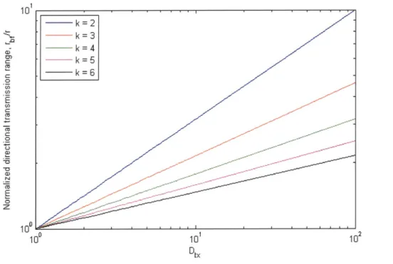
directional transmission range model for fixed transmission rate systems ... 53 2-4 Directional transmission range normalized by the omnidirectional transmission
range as a function of the transmitting antenna directivity ... 53 3-1 Example realization of random line network with anchored node 0 ... 62
3-2 Probability of connectivity and upper and lower bounds for random line
networks using omnidirectional antennas for different values of the normalized om nidirectional transm ission range ... 64
3-3 Probability of connectivity and upper and lower bounds for random line
networks using omnidirectional antennas for different values of the normalized omnidirectional transmission range on a log-log plot ... 64 3-4 Probability of connectivity and upper and lower bounds for random line
networks using directional antennas for different values of antenna directivity.. 68 13
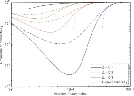
3-5 Probability of connectivity and upper and lower bounds for random line
networks using directional antennas for different values of antenna directivity on a log-log plot ... 68 3-6 Probability of connectivity and upper and lower bounds for random line
networks using directional antennas for different values of the attenuation exp o n en t ... 7 0 3-7 Probability of connectivity and upper and lower bounds for random line
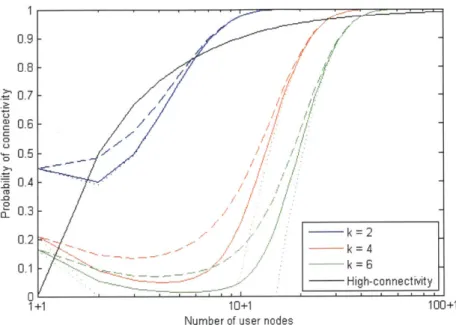
networks using directional antennas for different values of the attenuation exponent on a log-log plot ... 70 3-8 Probability of connectivity comparison between nodes equipped with
omnidirectional transmit antennas and beamforming-capable antenna arrays ... 71 3-9 Probability of connectivity comparison between nodes equipped with
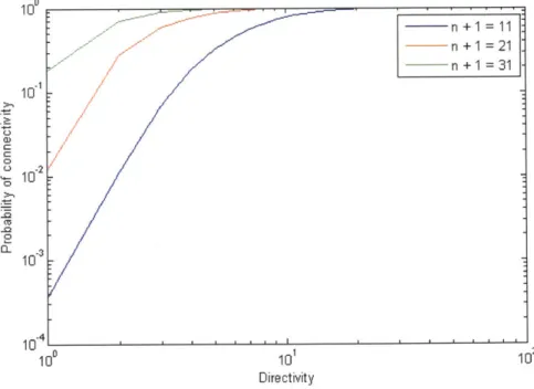
omnidirectional transmit antennas and beamforming-capable antenna arrays on a log -log p lot ... 7 1 3-10 Probability of connectivity versus transmitter directivity for selected values of
the num ber of end-user nodes ... 72 3-11 Probability of connectivity versus transmitter directivity for selected values of
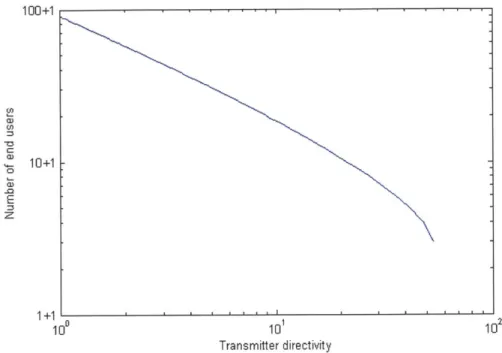
the number of end-user nodes on a log-log plot ... 72 3-12 Number of end-user nodes required to achieve a high probability of
connectivity in a random line network as a function of transmitter directivity .... 74
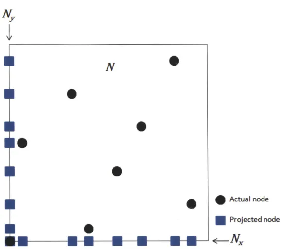
3-13 Example realization of random 2-D network and its associated one-dimensional
p rojection s ... 7 7
3-14 Example where both one-dimensional projections are connected, but the actual realization of the 2-D network has a partitioned node ... 78 3-15 The "balls and bins" model with appropriate tessellation of the operating region 81 3-16 Example of disconnected balls and bins approximation, whereas the underlying
netw ork realization is actually connected ... 81 3-17 Upper and lower bounds on the probability of connectivity for random planar
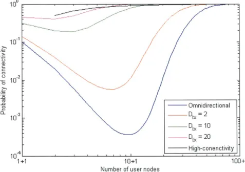
networks using omnidirectional antennas for different values of the normalized om nidirectional transm ission range ... 86 3-18 Upper and lower bounds on the probability of connectivity for random planar
networks using beamforming-enabled antennas for different values of the transm it antenna directivity ... 86
3-19 Lower bounds on the probability of connectivity for random planar networks
for both omnidirectional and directional systems shown simultaneously ... 87 3-20 Lower bounds on the probability of connectivity for random planar networks
for both omnidirectional and directional systems shown simultaneously on a
log -lo g p lo t ... 87 3-21 Number of end-user nodes required to achieve a high probability of
connectivity in a random planar network as a function of transmitter directivity for several values of the operation environment attenuation exponent ... 90
4-1 Example network that achieves the uniform capacity lower bound for networks w ith fixed rate transm issions... 104 4-2 Characteristic hopping distance as a function of beamforming-enabled
transmitter directivity for two different systems ... 116 4-3 Maximum end-to-end delay behavior (normalized to omnidirectional case) as a
function of the transmitter directivity factor ... 117
4-4 Visualization of three different routing schemes ... 121 4-5 Comparison of throughput scaling behavior of 0(1) hop routing strategies to
W hisper to the Nearest Neighbor routing ... 123 5-1 Adjacency matrix for four end-user node network and equivalent undirected
graph representation ... 133 5-2 Adjacency and cost matrices for three end-user node network and equivalent
weighted undirected graph representation ... 136 5-3 Illustration of the main idea behind the operation of Dijkstra's Shortest Path
A lgorith m for routing ... 138
5-4 Example of the operation of the Dijkstra-based Widest Path Algorithm ... 140
5-5 Polar coordinate system used in the description of our heuristic routing algo rith m s ... 15 1
5-6 Illustration of additional parameters used in our heuristic routing algorithms ... 152 5-7 Example fixed rate network that illustrates the changes required in our heuristic
List of Notation
D Transmitting antenna aperture size
* Transmitting signal wavelength (Chapter 2)
* Uniform traffic model data rate (Chapter 4)
Pr Received power
Pt Transmitted power
k Attenuation exponent of the path loss model d Distance between transmitter and receiver do Reference distance for path loss model
y Frequency and antenna gain constant in path loss model
W System bandwidth
n Number of end-user devices in network
NE Number of discrete antenna elements in uniform circular antenna array
(UCAA)
R * Radius of array or aperture antenna (Chapter 2)
* Fixed transmission rate of fixed rate system (Chapter 4 and 5) U(d, 0,
P)
Radiated fieldPrad Total time-averaged radiated power constraint G (0, P) Directive gain
Nsat UCAA element saturation point
Darray Directivity of the UCAA
Drx r rbf L
Xi
X(o)
Yi A Pc""l (n, A)phrf(n, A, Dtx)
NNx
Ny
P2DMn"t(n,A)
Pf (n, A, D,)
m
pbb(~mPC(n, m)
It ni n*A
AbfA
Abf PavgRi;
di;
Pi'
t
Transmit antenna directivity Receive antenna directivity
Transmit range of omnidirectional transmitter in fixed rate system Transmit range of directional transmitter in a fixed rate system
Length of operational line in 1-D network, or dimension of operational area in 2-D network
Unordered location of end-user node i Ordered location of end-user node i
Spacing between ordered node X(i) and X(ig,)
Normalized omnidirectional transmission range in fixed rate system
Probability of connectivity for 1-D omnidirectional network in fixed rate system
Probability of connectivity for I -D directional network in fixed rate system Random 2-D network
Projection of random 2-D network onto the x-axis Projection of random 2-D network onto the y-axis
Probability of connectivity for 2-D omnidirectional network in fixed rate system
Probability of connectivity for 2-D directional network in fixed rate system Number of cells (bins) in balls and bins approximation
Probability of connectivity for 2-D network under balls and bins approximation
Indicator random variable that cell i is empty in balls and bins approximation Number of nodes (balls) needed in the ith stage of deployment
Number of end-user nodes needed for at least one in each cell (bin) in balls and bins approximation
Uniform capacity of omnidirectional network Uniform capacity of directional network
Uniform throughput of omnidirectional network Uniform throughput of directional network
Total time-averaged power constraint for both transmission and processing Data rate between node i and node
j
Shannon Capacity of link (i,j) Distance between node i and node
j
No Noise spectral density
p" Time-averaged received power at node
j
from node i Rf Aggregate averaged transmitted data rate at node i Rr Aggregate averaged received data at node iPi Time-averaged total power consumed at node i in omnidirectional network ar Per bit energy cost for receiving data
ao Per bit energy cost for processing and storing received data a1 Per bit energy cost for storing and processing transmitted data
at Per bit energy cost for transmitting data
r1 Inverse of transmitting amplifier power conversion efficiency
Ppath Time-averaged source to destination path power consumption in
omnidirectional network
di Distance of the ita hop in a source to destination path a Total per bit energy cost for processing data
#
Total per bit transmission energy costPbf Time-averaged total power consumed at node i in directional network
Ph b Time-averaged source to destination path power consumption in directional
network
Pmax Maximum omnidirectional network hopping distance in fixed rate system
p Transmission hopping distance
Li Distance between the ith source-destination pair in the network
i
Average distance between all source-destination pairs under uniform trafficbf Maximum directional network hopping distance in fixed rate system
Pmax
A']
1M
Rate of traffic from node i to nodej
carried by link (1, m)dchar Characteristic hopping distance of omnidirectional network
ni Optimal number of hops in the route of the it source-destination pair
Lmax Maximum distance between all source-destination pairs under uniform traffic
d bf Characteristic hopping distance of directional network
v Dimension of square cell in cell routing scheme A Area of square cell in cell routing scheme
A Network adjacency matrix
a1 Individual element of network adjacency matrix
L Network localization vector
Network "cost" or "resource" matrix
Individual element of network cost matrix
Permanently labeled set of the Dijkstra-based Widest Path Algorithm
Estimate of the widest path width from node 1 to node i on the
tthiteration
of the Dijkstra-based Widest Path Algorithm
Initial angle of consideration for Algorithm 2
Angular increment for Algorithm 2
Initial radial range of consideration for Algorithm 2
Radial range increment for Algorithm 2
Chapter 1
Introduction
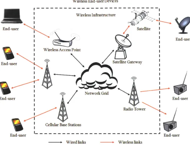
In recent years, wireless infrastructure has become widely prevalent and available to the end-user. This includes cellular base stations, private and public wireless access points, and even satellite gateways to access geosynchronous satellite communication systems. Wireless access to voice and data communication is becoming an embedded part of modern life; we expect to have instantaneous access to this technology wherever we are. However, this type of wireless access requires infrastructure and reliance upon a wired backbone network. Fig.
1-1 provides a basic schematic overview of the wireless communication world from an
infrastructure-based point of view. All of the wireless end-user devices are connected through high-capability wireless infrastructure points, which are in turn connected to one another through a wired network grid.
End-user
End-user
End-user
End-user
Wireless End-user Devices r
---Wireless
Infrastructure
Satellite
End-us( I Wireless Access Point
Satellite Gateway
I _ NNetwork Grid
End-user Radio Tower
Celular Base Stations
---
End-user
- Wired links Wireless links
Figure 1-1: An infrastructure-based wireless network.
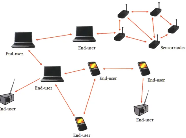
Future heterogeneous networks may need to incorporate infrastructureless wireless network
technology alongside the traditional infrastructure-based wireless network access. A large
body of work in wireless telecommunication has identified infrastructureless wireless
networks as an alternative to wireless infrastructure-based networks where there is
temporary and localized demand to communication capabilities and highly-contended or no
access to infrastructure points of wireless communication access. Infrastructureless wireless
networks are those which consist of end-user devices that can autonomously discover other
devices in proximity and establish direct network connections with them, becoming data
relays for source-destination pairs that cannot establish efficient one-hop connections. Fig.
End-user
End-user
End-user
End-user Sensor nodes
End-user
End-user
End-user
End-user
Figure 1-2: An infrastructureless wireless network.
1-2 shows a schematic example of an infrastructureless wireless network formed purely of
wireless connections between autonomous, untethered wireless devices.
Since an infrastructureless wireless network does not rely on the availability of pre-deployed
infrastructure, it can be rapidly deployed and autonomously configured in challenging
environments where temporary communication capabilities are required. We now describe
a few driving applications that create challenges for traditional infrastructure-based wireless
networks and identify the need for this infrastructureless wireless network technology.
* Wartime communications-Future combat theaters may contain a large number of
wireless
communication
devices,
including
personal
handheld
devices,
communication devices affixed to ground and aerial vehicles, sensor nodes, and even
communication modules included in autonomous robotic units. In a foreign combat zone, a military force may not have access to local points of wireless communication infrastructure. Furthermore, pre-operation deployment of fixed infrastructure is often infeasible and undesirable as these points would both constrain operational flexibility and present tactical targets for destruction.
" Disaster relief-Natural causes may cripple local wireless communication infrastructure, making relief effort communication impossible through traditional wireless access points. In a scenario like this, emergency response teams need a way to coordinate the relief and rescue effort in a quick and efficient manner. It is normally mission-infeasible to first concentrate on re-establishing communication infrastructure, thus an autonomous infrastructureless wireless network is an alternative means for telecommunication ability for this localized burst of wireless device presence. A purely satellite-based network is not a viable alternative because of the high cost associated with this infrastructure.
* Remote communication-Some distant or underdeveloped regions may not have established wireless infrastructure. In this case, an infrastructureless wireless network can allow for increased communication reach into these areas without the need for the build-up of costly access points and wired connections, even if this is only used as a temporary means of network access to these locations.
We can additionally imagine that infrastructureless wireless networks could aid in relieving high user-demand on the limited infrastructure-based network resources by diversifying available communication options to the end-user device. For example, the gravity and urgency of a disaster relief scenario could lead to high network loading and severe contention at wireless access points, such that some users may be denied the communication capacity required to participate in the relief effort to those in dire need. The additional
availability of infrastructureless wireless communication could allow these blocked users to remain connected to those leading rescue and relief teams.
The benefits of an infrastructureless wireless network do not come without a price; successful deployment of these networks is impeded by many unsolved technical problems. There is increased computational and power demand on each end-user device, since end-user nodes in these networks must serve as relay points for communication in addition to acting as data sources and sinks. Further complexity arises from the volatile nature of the wireless environment, where an end-user may be powered down at any given time, any communication link along a path is subject to a multitude of wireless RF effects like fading, shadowing, and nearby device interference, and user mobility gives rise to rapidly changing network topologies. Catastrophically, a device may even move beyond the communication range of all other end-user devices and become temporarily or permanently partitioned from the network.
Many of the driving applications for infrastructureless wireless networks, including tactical military communication and disaster relief, require stringent quality of service (QoS) guarantees, particularly in data throughput, end-to-end message delay, and network power consumption. While throughput requirements may be low to moderate, needing only to support text-based messages, guaranteed instantaneous access to communication resources to support the transmission and relay of these messages may be required. Applications like these may demand higher levels of end-to-end message latency guarantees. Since stale information becomes useless in time-critical scenarios such as wartime and disaster relief communication, a message may have a lifetime of only a few seconds and thus must reach its recipient or recipients in the time scale of seconds or less. Network power consumption must be simultaneously considered alongside throughput and end-to-end delay performance since many untethered wireless devices that are part of an infrastructureless wireless
network rely on battery power. The need to be instantaneously connected to send or receive time-critical data messages means that devices must conserve power as possible to maximize device lifetime. These challenges, while difficult to meet, become impossible to consider without first addressing the issue of determining and maintaining infrastructureless wireless network connectivity. The ability to satisfy QoS requirements, particularly with respect to end-to-end sustainable data rate and message delay, is dependent first and foremost on network connectedness. Sustainable throughput and end-to-end delay guarantees to the end-user cannot be provided in a partitioned network. And if infrastructureless wireless networks are to become a widely-adopted communication modality in future commercial heterogeneous networks outside of these driving application examples, the ability to address network connectivity and, subsequently, end-to-end throughput and data latency guarantees will become increasingly important to satisfy the QoS demands of familiar civilian network
applications, including real-time streaming video and financial trading.
1.1 Current and Proposed Approaches
The needs and challenges of the infrastructureless wireless network problem has led to research in ad-hoc mobile wireless networks (MANETs) that offer best-effort network connectivity (see [1,2]). Commonly, ad-hoc wireless networks refer to networks in which every device is capable of message forwarding and where messages may potentially take multiple wireless hops from the source node to the destination node. This framework often includes wireless sensor networks [3,4], which have enjoyed relative success. Work on MANETs has been active for nearly three decades. Despite large strides in many of the fundamental problems in the wireless ad-hoc network architecture, including physical layer issues, random access considerations, and network-layer routing, there has been limited
practical adoption of MANET architectures [5]. These networks are generally not designed to provide for QoS assurance. Devices in a MANET may be often disconnected due to the combination of low device density, end-user mobility, and the lack of an architecture that proactively seeks to maintain network connectivity and meet application and network demands.
The most prominent research effort to address the problem of infrastructureless wireless connectivity for mobile end-users has been Disruption Tolerant Networking. The Internet Research Task Force (IRTF) formed the Delay-tolerant Networking Research Group (DTNRG) in 2002 to propose an architecture and protocol design for network scenarios where instantaneous end-to-end network connectivity cannot be assumed [6,7]. This work further spawned the DARPA-funded Disruption Tolerant Networking (DTN) program in
2005 [8]. Motivated by interplanetary networking, this architecture is grounded in a
store-and-forward networking approach, where each relay node stores incoming messages until communication opportunities present themselves and allow the message to be forwarded to the next hop along a path that will eventually reach the destination. While this approach is sensible in the interplanetary domain of orbiting celestial bodies and geosynchronous satellites, the DTN architecture does not consider providing assurance levels to QoS measures like end-to-end delay. Messages may be delayed within the network for long durations waiting for an appropriate communication opportunity in this architecture. Thus, DTN is only suitable for applications that are delay-insensitive, in stark contrast to the driving applications for infrastructureless wireless networks that we have discussed.
Whereas the DTN architecture makes no attempt to proactively maintain connectivity between mobile users in the network, [9] argues that service assurance in infrastructureless wireless networking environments can best be achieved by an architecture that proactively predicts potential network disconnections and responds by allocating resources to maintain
network connectivity. The author proposes two features of a proactive architecture that support throughput and delay QoS requirements: (1) network disconnection prediction using localization, trajectory prediction, and large-scale channel estimation and (2) topology control through the deployment of mobile relay nodes that provide support at areas of predicted network disconnection. The results presented by this work suggest that the ability to predict and proactively combat network partitioning is a keystone to providing QoS guarantees in the infrastructureless wireless network scenario. Adhering to this insight, the work of this thesis focuses first on possible improvements for infrastructureless wireless network connectivity, and the identified high-connectivity regimes are those that are of primary interest in subsequent analytical study.
In addition to the techniques introduced in [9], other approaches to address connectivity and
QoS
assurance issues in infrastructureless wireless networks have been proposed [10]. These include:" Beamforming-This is a "smart antenna" technology that uses electronic signal
processing techniques at the multi-element transmitting antennas to focus radiation energy towards the receiver through constructive interference, while providing receivers the opportunity to place nulls in the direction of interferers. Receiver array processing techniques also enable receive beamforming. These antenna array processing techniques can be used either to reduce required power allocation for a given transmission rate, to increase the achievable bit rate between a communication pair, or to increase transmitter reach, while leveraging directionality to reduce interference noise levels from other transmitters in the infrastructureless wireless network.
" MIMO-Diversity receivers and transmitters attempt to excite multiple independent
wireless modes between the transmitting wireless device and the receiving wireless device when available. This technique takes advantage of wireless multipath effects
to achieve throughput gains without additional power or bandwidth allocation. This "smart antenna" technique requires the existence of RF reflectors and multiple stable paths, and thus may not be a feasible approach when end-user nodes are highly mobile or in an uncluttered RF environment where the only stable path between transmitter and receiver is line-of-sight (LoS).
New Transport Layer Protocol-Transmission Control Protocol (TCP) is the primary transport layer protocol in today's Internet. Its attractive features include end-to-end reliability, congestion control, transmission rate control, and a notion of fair network resource allocation to different users. However, this protocol was designed for a stationary network topology composed primarily of wired links. It does not distinguish between congestion-based losses and losses resulting from wireless RF phenomena, and its functions break down under frequent losses that lead to underutilization of available network resources. A new protocol that addresses these inefficiencies in the heterogeneous network domain while preserving the goals of end-to-end reliability, congestion control, rate matching, and fair resource allocation would help to maintain high-throughput and low-delay end-to-end connections in the infrastructureless wireless network setting.
1.2 Scope of Thesis Work
Recognizing the need for improved connectivity in infrastructureless wireless networks in order to meet application QoS demands, this thesis focuses on a combination of electronic beamforming (the first of the proposed techniques mentioned at the end of Section 1.1) and the use of localization and channel state estimation, as in [9]. Directional transmission and reception using electronic antenna array processing techniques provides several significant
benefits in the infrastructureless wireless network domain that can be used to address the issues encountered in traditional MANET research, including:
e Reach-By focusing the antenna power radiation pattern in a localized direction of interest, the communication range of a power-constrained fixed transmission rate end-user can be extended beyond that of a fixed rate transmission device using an omnidirectional radiator.
" Data rate/power tradeoff-At the same transmit power level, a communication pair
can exchange information at a higher bit rate than if they were using omnidirectional antennas. Alternatively, a communication pair can exchange information at a particular bit rate while using less power for data transmission than if they were using omnidirectional radiators.
* Pass-through traffic reduction-Given the increased transmitter reach in a fixed transmission rate system, beamforming-enabled nodes are able to forward messages along a route that eliminates unnecessarily short intermediate hops required of a network using only omnidirectional antennas with identical transmission power constraints. This, in turn, decreases the pass-through traffic load on intermediate end-user devices that would have to act as data relays in the omnidirectional network case.
" Interference suppression-Focusing energy in the direction of the intended receiver
reduces the interference levels at ancillary receivers in the network outside the main beam (and any significant side lobes), thus reducing interference noise and overhearing when compared to the omnidirectional network in which transmitted power is radiated equally in all directions regardless of the intended receiver location.
" Interference nulling-A receiving end-user can strategically place nulls to cancel out
* Spectrum reuse-Focused radiation patterns allow neighboring network nodes to transmit to separate receivers on the same frequency channel without creating unwanted interference at the receivers.
This work focuses on a power-limited network model, which is in contrast to related work in the area that considers an interference-limited network model (as made famous by [11]). The interference-limited model is well-studied in the context of infrastructureless wireless networks, including some results using beamforming-enabled end-user nodes [12]. Bandwidth scaling is a physical layer system option that has been shown to improve the scalability of network performance with respect to sustainable throughput, end-to-end delay, and network power consumption. Given large enough system bandwidth, network performance is limited by the end-user power consumption rather than the interference and overhearing levels at the receiver. Bandwidth scaling is used as an analytical technique here since it allows our results to focus on the effects of increasing the probability of network connectivity with beamforming-enabled end-user nodes.
This work considers an infrastructureless network of power-limited wireless devices equipped with localization capability, Global Positioning System (GPS) hardware for example, and multi-element antenna arrays or apertures capable of transmit and receive beamforming. While long-accepted as an important feature in satellite communication [13], multi-element antenna arrays and transmit and receive beamforming have recently been shown to provide gains in achievable capacity in the infrastructureless wireless setting [14]. Furthermore, node localization information has been shown to provide throughput and end-to-end latency gains in infrastructureless wireless networks when combined with a strategy that can exploit this information to promote network connectivity [9]. In our context, localization information is required for a transmitting node to focus its transmission beam in the direction of the intended receiver, and antenna array processing can be viewed as a
strategy to exploit user location information to promote network connectivity by overcoming RF effects and the disconnection of nodes that lie beyond the reach of an omnidirectional network. The combination of these techniques creates an improved network topology that can address core service traffic demands through improved connectivity and, subsequently, achievable throughput, end-to-end delay, and power consumption.
1.3 Thesis Organization
The following is a brief description of the organization of this thesis.
Chapter 2 introduces the assumptions, models, and technologies that are used throughout the work. Specifically, it describes the RF and channel model used in the network analysis, an overview of beamforming and the associated transmission model, and a condensed overview of localization technology that could be used to provide geolocation information to the network end-users.
Chapter 3 considers the improvement in infrastructureless wireless network connectivity from beamforming in randomly deployed networks of a finite number of stationary end-user nodes. The analysis is done in both one and two dimensions. This study identifies regimes of high probability of connectivity, which is of interest in subsequent chapters that study the scaling behavior of QoS metrics.
Chapter 4 examines the scaling behavior of throughput, end-to-end delay (in terms of number of end-to-end hops), and energy consumption in power-limited infrastructureless
wireless networks with beamforming-enabled end-user devices and large-enough system bandwidth. After characterizing capacity bounds of these networks for any arbitrary topology of a finite number of end-users, we show that the throughput-optimal scaling behavior can be achieved alongside the delay-optimal and per bit energy-optimal scaling behavior, all of which are independent of increasing end-user device density.
Chapter 5 develops routing algorithm solutions for both the omnidirectional and directional infrastructureless wireless network that optimize over individual QoS metrics of interest. Insight from Chapter 4 is then employed to develop a heuristic routing algorithm that achieves the scaling-optimal behavior for all QoS metrics of interest simultaneously.
Chapter 6 provides a summary of the thesis results and discussion of possible future research topics.
Chapter 2
Models, Assumptions, and Technologies
We consider wireless infrastructureless networks with beamforming-enabled end-user nodes and their capability to provide some level of QoS guarantees that will enable this type of network to be used for scenarios and applications with stringent service requirements. Whereas similar work has focused on the addition of autonomous helper relay nodes to promote connectivity for delay-sensitive services [9], we are interested in addressing instantaneous network connectivity and QoS performance using array or aperture antennas and onboard signal processing technology, along with geolocation information in order to extract the full benefit of beamforming-capable antenna systems. Otherwise, the wireless infrastructureless network that this work considers is the same as traditional MANETs: the network is a set of wireless end-user devices that autonomously form a network in a given operating environment and then proceed to generate, sink, and forward data as necessary.
We note that this work does not consider end-user mobility in the presented analysis. Although the mobility of untethered wireless devices is an important feature of an infrastructureless wireless network, we can see this stationary network deployment analysis as a snapshot of a dynamic network on an appropriate time scale with respect to the degree of node mobility. Considering the probability of connectivity and network QoS performance behavior of these stationary snapshots is necessary before including an end-user mobility model as part of the analysis.
This chapter has several goals. First, we explain exactly what kind of service we wish to provide to end-users through this type of infrastructureless wireless network. Second, we discuss various models that are used throughout the remaining chapters to facilitate analytical study of the proposed system. This discussion of models focuses on the RF environment and channel model that we use throughout, along with the antenna and transmission model that is employed when discussing beamforming-enabled end-user devices. To this end, we begin by discussing beamforming in general, which motivates the transmission model. Our work requires an additional network power consumption model. However, the development of this model is deferred to Chapter 4, where it is required for the analysis presented. Finally, the last part of this chapter touches upon localization technology, another tool that we assume to be at the disposal of the end-user devices in our
2.1 Core Services
In proposing an infrastructureless wireless network design capable of supporting throughput-and time-critical data applications, we need to distinguish the class of service that we are considering. In general, there are two main classes of service: best-effort and guaranteed
QoS
(or "core"). Best-effort services are for those messages without stringent requirements on throughput and end-to-end latency. Core services provide for mission critical messages that come with a pre-specified set of QoS requirements that need to be satisfied, such as required throughput and end-to-end latency. Core services messages are given priority over those in the best-effort class. Considering the applications discussed in Chapter 1, these core service messages may include critical military commands to be disseminated to a unit of troops or time-sensitive alert messages to be distributed to relief workers aiding response teams after a natural disaster.Since core services are at the forefront of consideration in this work, the next chapter is dedicated to analyzing how the use of beamforming-enabled devices can improve instantaneous network connectivity for fixed rate transmission systems. A connected
network is a prerequisite for providing QoS performance guarantees to end-users. In the absence of connectivity, the network throughput is zero between at least one end-user pair and the to-end message delay can be considered to be infinite between at least one end-user pair. A disconnected, or partitioned, network is a catastrophic condition when viewed in the context of the driving applications we have discussed.
As discussed in [9], instantaneous network connectivity is often ill-defined in the wireless setting. For variable rate transmission wireless systems, all pairwise end-users are theoretically connected and able to communicate in an obstacle-free RF environment, even
though the data rate they can support becomes arbitrarily small as the physical distance between the pair of nodes increases. Given an increasingly long interval of time, two users can exchange a finite length message even as their separation distance grows unbounded. We note that this is a theoretical scenario. In reality, there are device hardware limitations on the power threshold required for reception. Even so, an increasingly long interval of time is not a luxury that we can assume to have in a network intended to provide core services. For fixed rate transmission systems, users must communicate at a set rate when they exchange data. This imposes a limit on the range of a transmitter assuming that we have some transmission power constraint at the sender (a realistic constraint for a wireless system of untethered end-user nodes). It is in this type of fixed rate transmission system that we primarily discuss the metric of instantaneous network connectivity, since connectivity is a first requirement for providing core services. Throughout this work, we distinguish between fixed rate and variable rate transmission systems when necessary.
2.2 The RF and Channel Model
Before coming to beamforming and the transmission model, we begin with a discussion of the RF environment and channel model used in this work. These are necessary to understand the directional antenna transmission model that is discussed in the subsequent section.
2.2.1 Empirical Channel Model
For analytical simplicity, we assume that our networks operate in a simple one- or two-dimensional RF environment free of specific obstructions, absorbers, and scatterers. In a real world scenario, all of these would need to be considered based on the specific deployment environment, as they contribute to important time-varying wireless effects: shadowing and fading.
Instead, we focus on a simple and commonly-used empirical model for system analysis, the path-loss model. In free space, it is known that signal power at the receiver is inversely proportional to the square of the distance between transmitter and receiver. However, should there be imperfections in the RF environment, this relationship may not hold. The path-loss model combines the effects of typical propagation losses along with absorption and diffraction losses that may arise from an imperfect RF environment. We assume that our
2D2
receivers are in the antenna far-field (a distance of more than - from the transmitter, where D [m] is the transmitting antenna aperture size and A [m] is the signal wavelength). Then the path-loss model describes the power loss factor between the transmitter and receiver in dB:
[dB] = 10 log
1o y - 10k logio
d
(2.1)
where Pr [J/sec] is the received power, Pt [J/sec] is the transmitted power, and their ratio is the power loss factor. In (2.1), k is the path-loss exponent (sometimes called the attenuation exponent), usually in the range of 2 k 6, where k = 2 is free space propagation loss only, and k = 6 can be reached in some indoor environments. Furthermore, d [m] is the
distance between transmitter and receiver, do [m] is the reference distance (usually set to do = 1, as we use it throughout this thesis) and y is a constant accounting for system losses
that is a function of both frequency and antenna gain [15]. 39
The parameters of this model can be estimated either from theoretical analysis or empirical measurements. Throughout this work, we assume the existence of a homogeneous RF operating environment and that each end-user node is capable of making an estimate of the path-loss exponent in the particular operating environment. We also assume a homogeneous end-user device set throughout, and thus we allow y to be a constant for all nodes in the network. Finally, the value of d between any communicating pair is known to the network end-user devices since localization information is available to each node (see Section 2.4 on localization technology).
This model fails to account for important wireless RF phenomena that would realistically impact the system. Key parameters of a more sophisticated statistical channel model, such as shadowing and fading, are absent. These effects are typically modeled as random variables of particular statistics that are added to the path-loss model shown in (2.1). There is a large body of literature dedicated to studying different statistical channel models (see [15-28]). However, the parameters of these models are heavily dependent on the operating environment and communication frequencies used. While allowing for a more detailed description of the wireless channel, a more sophisticated channel model is not required for the analysis in this work. The use of the basic path-loss model here aims for simplicity and first-order intuition.
Alternatively, it is possible to use site-specific models for the wireless channel estimates. These models utilize detailed knowledge about RF obstacles in a given operating environment that are gathered a priori from available resources (such as maps and blueprints) or learned during system operation (such as with sensors designed to detect and map environmental obstacles). The interested reader is referred to Section 2.2.1 of [9] for a
concise overview of these models and methods. However, these more specific channel models are not pursued further in this work.
2.2.2 A Power-limited Network
A bulk of the literature analyzing wireless infrastructureless networks focuses on
narrowband systems (such as [11]). These systems are deemed interference-limited, since it is the signal interference from nearby transmitters that dominate the noise levels at the receivers. Wireless infrastructureless networks using directional antennas have been studied using this framework [12]. The work of Dai in [9] shows that significant improvements to network scalability through bandwidth scaling, where interference levels become negligible with the availability of large enough system bandwidth and appropriate channelization. In this regime, called the power-limited regime, the network performance is limited by the power available to each node.
Following this analytical lead, we consider wireless infrastructureless networks operating in the power-limited regime by assuming the availability of sufficiently-large system bandwidth. Analyzing network performance in the power-limited regime shows the best that we can achieve with the network architecture, since the inclusion of interference effects at the receivers will reduce achievable performance capabilities despite the ability of antenna arrays to null interfering signals. Analysis of the power-limited network gives an "upper bound" on system performance, although network performance can closely approach this upper bound with effective beamforming.
In the power-limited regime, we assume the availability of at least n(n - 1) available
frequency channels for a network with n end-user devices, such that each possible communication pair shares its own pair of unique communication channels. This channelization suppresses the effect of unwanted interference and overhearing at the receivers. For analysis, we model this as the limit of large bandwidth (W -> 00, where W is the system bandwidth). We assume that appropriate channel coding is used such that the capacity between any given pair of nodes is upper bounded by the Shannon Capacity for an additive white Gaussian noise (AWGN) channel.
2.3 Beamforming and the Transmission Model
The primary objective of this work is to compare the performance of an infrastructureless wireless network with end-user nodes equipped with beamforming-enabled antennas to one with end-user nodes using only omnidirectional transmit and receive antennas. To this end, we discuss a transmission model for the beamforming-enabled node that allows us to develop a comparative analysis between the two cases. This section first discusses beamforming technology generally, both from the transmission and reception ends. Then it develops the abstract model that we employ throughout the remainder of the work to distinguish between the two different network scenarios.
2.3.1 The Antenna Model
In this section, we distinguish between two main types of antenna models: the omnidirectional model and the directional model. The performance of an infrastructureless wireless network with nodes using omnidirectional transmit and receive antennas is well-studied and is considered as a baseline for comparison throughout this work. The directional beamforming antenna model is further subdivided into two categories: discrete element and continuous aperture. This follows the analytic presentation for antenna beamforming performance in infrastructureless wireless networks in [14].
We begin with the omnidirectional antenna model. This work analyzes infrastructureless wireless networks in both one- and two-dimensional scenarios. Regardless of the dimensionality of the operating area, we assume that end-user nodes use isotropic point-source radiators to produce a spherical radiation pattern. The isotropic point-point-source radiator is a theoretical antenna construction with absolute uniformity over its radiation pattern. Brouwer's hairy ball theorem of algebraic topology shows that a continuous vector field of uniform magnitude cannot be everywhere tangent to a sphere, thus proving that the ideal isotropic radiator is not a realizable entity [29]. However, this ideal radiator is often assumed in literature on omnidirectional antennas and is used to define directive gain, thus it is an acceptable model for the antennas used in the baseline omnidirectional network.
For the directional antenna model, we begin by considering an array of identical antenna elements that can concentrate power in an arbitrary direction in a two-dimension operational plane. The simplest antenna array geometry that can achieve this rotational symmetry in the plane is a uniform circular antenna array (UCAA). Each UCAA is made of NE discrete and identical antenna elements, indexed i