HAL Id: hal-01842360
https://hal.archives-ouvertes.fr/hal-01842360
Submitted on 18 Jul 2018
HAL is a multi-disciplinary open access
archive for the deposit and dissemination of
sci-entific research documents, whether they are
pub-lished or not. The documents may come from
teaching and research institutions in France or
abroad, or from public or private research centers.
L’archive ouverte pluridisciplinaire HAL, est
destinée au dépôt et à la diffusion de documents
scientifiques de niveau recherche, publiés ou non,
émanant des établissements d’enseignement et de
recherche français ou étrangers, des laboratoires
publics ou privés.
Separator electrode assembly (SEA) with 3-dimensional
bioanode and removable air-cathode boosts microbial
fuel cell performance
Manon Oliot, Luc Etcheverry, Annette Mosdale, Régine Basséguy, Marie-Line
Délia-Dupuy, Alain Bergel
To cite this version:
Manon Oliot, Luc Etcheverry, Annette Mosdale, Régine Basséguy, Marie-Line Délia-Dupuy, et
al.. Separator electrode assembly (SEA) with 3-dimensional bioanode and removable air-cathode
boosts microbial fuel cell performance. Journal of Power Sources, Elsevier, 2017, 356, pp.389-399.
�10.1016/j.jpowsour.2017.03.016�. �hal-01842360�
OATAO is an open access repository that collects the work of Toulouse
researchers and makes it freely available over the web where possible
Any correspondence concerning this service should be sent
to the repository administrator:
[email protected]
This is an author’s version published in: http://oatao.univ-toulouse.fr/n° 20362
To cite this version: Oliot, Manon
and Etcheverry, Luc
and
Mosdale, Annette and Basséguy, Régine
and Delia-Dupuy,
Marie-Line
and Bergel, Alain
Separator electrode assembly
(SEA) with 3-dimensional bioanode and removable air-cathode
boosts microbial fuel cell performance. (2017) Journal of Power
Sources, 356. 389-399. ISSN 0378-7753
Official URL:
http://doi.org/10.1016/j.jpowsour.2017.03.016
Open Archive Toulouse Archive Ouverte
Separator electrode assembly (SEA) with 3-dimensional bioanode and
removable air-cathode boosts microbial fuel cell performance
M. Oliot
a,*, L. Etcheverry
a, A. Mosdale
b, R. Basseguy
a, M.-L. D!
elia
a, A. Bergel
aaLaboratoire de G!enie Chimique CNRS - Universit!e de Toulouse (INPT), 4 all!ee Emile Monso, 31432 Toulouse, France bPaxiTech SAS, 32 rue de Comboire, 38130 Echirolles, France
h i g h l i g h t s
!The separator membrane assembly with a grid as the separator performed the best. !Efficient pH balance by diffusion of the buffering species is essential.
!Oxygen crossover was mitigated by the biofilm on the cathode and the 3D bioanode. !Biofouling did not impact the resistance; fouling deteriorated the cathode kinetics. !All bioanodes showed stringent selection of Proteiniphilum acetatigenes.
Keywords: Microbial anode pH balance Biofouling Proteiniphilum Power density Bioelectrochemical system
a b s t r a c t
Separator electrode assemblies (SEAs) were designed by associating a microbial anode with an air-cathode on each side of three different kinds of separator: plastic grid, J-cloth and baking paper. The SEA was designed to allow the air-cathode be removed and replaced without disturbing the bioanode. Power densities up to 6.4 W m"2were produced by the Grid-SEAs (on average 5.9 ± 0.5 W m"2) while JCloth-SEAs and Paper-SEAs produced 4.8 ± 0.3 and 1.8 ± 0.1 W m"2, respectively. Power densities
decreased with time mainly because of fast deterioration of the cathode kinetics. They always increased again when the air-cathodes were replaced by new ones; the Grid-SEAs were thus boosted above 4 W m"2after 7 weeks of operation. The theoretical analysis of SEA functioning suggested that the high
performance of the Grid-SEAs was due to the combination of several virtuous phenomena: the efficient pH balance thanks to free diffusion through the large-mesh grid, the likely mitigation of oxygen cross-over thanks to the 3-dimensional structure of the bioanode and the possibility of cross-overcoming cathode fouling by replacing it during MFC operation. Finally, the microbial community of all bioanodes showed stringent selection of Proteiniphilum acetatigenes in proportion with the performance.
1. Introduction
Microbial fuel cells (MFCs) can convert the chemical energy contained in a large variety of organic compounds[1,2]directly into electrical energy. They are composed of a microbial anode, which oxidizes organic matter thanks to the catalytic activity of anode-respiring bacteria, associated with a cathode, which most often ensures oxygen reduction [3]. Considerable advances have been made on microbial anodes[4e7]but the power density achieved still remains modest. It generally does not exceed one or two
W m"2[8]. Values of the order of 7 W m"2[5,9]have been reported but by expressing density with respect to the anode surface area, which, in this case, was considerably smaller than that of the cathode. Nevertheless, on the basis of the cathode surface area, to the best of our knowledge, the highest power densities reported so far are of the order of 4.7 W m"2[10]. Furthermore, power density generally falls when the MFC volume increases. For instance, it has recently been claimed that 2 W m"2is the highest power density reported for a single compartment MFC with a volume greater than 100 mL[11].
There are other causes but the low ionic conductivity of the electrolyte used in MFCs is largely responsible for such poor per-formance. Electroactive biofilms are generally sensitive to high salinity and, except those formed in marine sediments [12e16],
*Corresponding author.
microbial anodes require a low-salinity medium. The ionic con-ductivity of MFC electrolyte is generally around 1 S m"1and often less, down to 0.1 S m"1 [17,18], when the objective is to treat wastewater. In this context, a major objective has been to reduce the internal resistance of MFCs by minimizing the anode-cathode distance. However, this can increase oxygen crossover from the cathode to the anode, which inhibits or kills electroactive bacteria or shifts them from anode respiration to aerobic respiration. It is generally agreed that a distance of 1e2 cm is the optimum [8,19e21].
Promising paths towards further reduction of the anode-cathode distance while minimizing oxygen transfer to the anode, have been opened up by separator-electrode assemblies (SEA) [20,22]. The nature of the separator is essential. It must minimize oxygen diffusion while impeding ionic transfer as little as possible in order to keep the ionic resistance at a minimum and avoid up-setting the pH balance between the anode, which produces pro-tons, and the cathode, which produces hydroxide ions[23]. Porous separators, and particularly macro-porous separators such as textile material, glass fibre and J-cloth, have led to interesting performance levels with fairly low cost separator materials [20,22,24e26].
In association with porous separators, three-dimensional an-odes, like carbon mesh or fibre brush, applied against the separator surface have been observed to perform better than flat anodes [22,27,28]. It has been speculated that aerobic bacteria growing on the anode or on the separator itself consume the oxygen that dif-fuses from the cathode and thus permits stable anoxic zones to develop in the three-dimensional anode [8,28]. Using a three-dimensional bioanode to build an SEA consequently reduces the importance of finding a separator structure that minimizes oxygen diffusion.
Here, we chose to have full confidence in the capacity of an electroactive biofilm to self-organize so as to protect itself against oxygen crossover, provided that it was provided with a three-dimensional structure to develop on. SEAs were consequently built with three-dimensional bioanodes and large-mesh plastic grids used as the separators, the sole mission of which was to prevent electrical short-circuiting between anode and cathode. Ion transport was thus not impeded, except by the low volumetric hindrance of the grid. For comparison, similar SEAs were tested in identical conditions, using J-cloth or baking paper as the separator. Finally, a recent study performed with a separated anode-cathode configuration has shown that the initial biofouling of the air-cathode is a major cause of performance underestimation[29]. It described a device that allowed the air-cathode to be removed and replaced without disturbing the MFC operation. It was thus observed that cathode biofouling occurred very fast, from the beginning of MFC operation, and led to the MFC performance being significantly underestimated. Here, a similar removable air-cathode system was developed with an SEA. It was thus possible to set the air-cathode into the SEA only after the bioanode was fully devel-oped. This procedure avoided biofouling of the air-cathode during the preliminary phase of bioanode formation and allowed the initial performance of the SEAs to be assessed in optimal conditions.
2. Materials and methods
2.1. SEA and MFC design
The MFC consisted of a 400 mL cube in poly(methyl methacry-late) with a lid screwed on the top face. The lid was equipped with two small holes for electrical wiring of the bioanode and the auxiliary electrode and with a 1.2-cm diameter hole for the
saturated calomel reference electrode (SCE, potential 0.24 V/SHE), with respect to which all potentials were expressed. The auxiliary electrode was a platinum grid (Heraeus SAS, Germany). The holes used for electrical wiring were hermetically sealed so that the MFC could be turned into a lying position without liquid leaking out. Gas could escape through the reference hole. One face had a circular opening 3.5 cm in diameter, on which the SEA was set-up. The active surface area of the SEA was thus 9.6 cm2and all current and power density values were calculated with respect to this surface area.
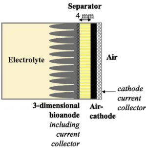
Separator-Electrode Assemblies (SEAs) were designed by sand-wiching the separator between a carbon cloth bioanode and an abiotic air-cathode. Carbon cloth (PaxiTech, Grenoble, France) was used as the bioanode support. It was pleated into multiple folds around 1 cm wide to obtain a 3-dimensional structure, which was applied and sewn on to a stainless steel grid used as the bioanode current collector (Fig. 1). The bioanode was held against the sepa-rator mechanically. Three different types of sepasepa-rator were tested, each in duplicate:
- a plastic grid with 5 mm mesh; two layers were superimposed, leading to a total thickness of 4 mm, in order to be sure to avoid short-circuiting by anode bristles[25];
- J-cloth with pore diameter around 1 mm; three layers were superimposed, leading to a total thickness of 2 mm;
- baking paper, produced from chemical pulp of deciduous trees, with a pore size of around 15
m
m and a thickness of 1 mm.Whatever the separator thickness, the same anode-cathode distance of 4 mm was kept constant in order to enable a fair comparison. The air-cathode (0.5 mg/cm2platinum load, 10% PTFE layer, PaxiTech, Grenoble, France) was applied against the separator with a perforated stainless steel plate used as the current collector (Fig. 1). The SEA was maintained by a drilled poly(methyl methac-rylate) ring sealed with an O-ring and screwed on to the reactor side. It was thus possible to unscrew the ring and to remove and replace the cathode and/or the separator without disturbing the bioanode. For this operation, the reference electrode was firstly removed and replaced by a hermetic stopper and the MFC was turned into the lying position to put the SEA on the top face.
2.2. Bioanode formation
Primary bioanodes were firstly formed in compost leachate independently of the MFC as previously described[30]. These pri-mary bioanodes were then used as the inoculum to form the SEA bioanodes in the MFC devices[31,32]. MFCs were filled with syn-thetic medium (bicarbonate buffer 50 mM, macronutrients 10 mL L"1, micronutrients 1 mL L"1, vitamins 1 mL L"1, KCl 4.5 g L"1 and NaH2PO42.4 g L"1; pH adjusted to 7.0) and acetate 20 mM was
used as the substrate. The ionic conductivity of the medium was 1.25 S m"1. During the phase of bioanode formation, the SEAs had a silicone foil in place of the air-cathode and the bioanodes were polarized against the platinum grid auxiliary electrode. The pri-mary bioanode (inoculum) and the SEA bioanode were electrically connected together and polarized at "0.2 V/SCE using a VSP potentiostat (Bio-Logic SA, France). Bioanodes were formed for around 1 week, which corresponded to 5 successive batches with acetate 20 mM. Temperature was maintained at 40#C in a
heat-chamber. Finally, the synthetic medium was replaced by a fresh one and bioanodes were polarized for one additional day.
2.3. MFC operation
MFC operation was started by replacing the silicone foil by an air-cathode to form the complete SEA. During MFC operation, the temperature was maintained at 40#C in a heat-chamber and
ace-tate concentration was maintained at 20 mM by periodic mea-surement (Megazyme K-Acetak kit, Ireland) and addition. Power curves were recorded periodically, using a variable external elec-trical resistance ranging from 0 to 33,000
U
. A high-impedance voltmeter (Keithley, 2000 multimeter, USA), in derivation of the resistance, measured the cell voltage and a second voltmeter measured the anode and cathode potentials versus the SCE refer-ence. MFCs produced power continuously through an electrical resistance, which was adjusted, generally in the range 10e100U
, so that the MFCs operated close to their maximum power.2.4. Galvanostatic electrochemical impedance spectroscopy
Internal ionic resistance was measured by galvanostatic elec-trochemical impedance spectroscopy (EIS). A two-electrode set-up was used with the bioanode as working electrode and the air-cathode as both auxiliary and reference electrodes. Measure-ments were made in duplicate at two current values: 5 and 10 mA (range of the current delivered by the MFCs). The signal amplitude was 50
m
A for 5 mA and 100m
A for 10 mA. Current was firstlyimposed on the system for 5 min to reach a stationary state and then the potential was scanned recording 10 points per decade. EIS was implemented only at high frequency from 100 kHz to 10 kHz in order to measure the ionic resistance (RS) between the anode and the cathode, given by the real part in the Nyquist plane. RSwas the sum of all the resistances to ion motion between the anode and the cathode including the biofilms and the separator.
2.5. Diffusion coefficient measurement
Diffusion coefficients of OH"
through the J-cloth and the paper separators were assessed experimentally in abiotic conditions. A two-compartment H-shaped cell (modified Schott glass, Duran) was used with an H junction of 7 cm2cross sectional area. Three sheets of J-cloth (total thickness ¼ 2 mm) or one sheet of paper (thickness ¼ 0.1 mm) were set in the H junction, in order to have the same separation characteristics as in the MFCs. The two com-partments were filled with 700 mL of a solution of NaOH at pH 8 and stirred. The pH of compartment n#
1 was adjusted to 11 with a
1 M NaOH solution and the pH in each compartment was measured over time. The mass transfer coefficient (kHO-, m.s"1) was extracted from the measurements as:
kHO"¼ " V A % t%ln !C 1;0"C2 C1;0 " (1)
where V is the compartment volume (m3), A the separator cross-section area (m2), C1,0the initial OH"concentration in
compart-ment 1 (mol m"3) and C2 the concentration in compartment 2
(mol m"3) at time t (s).
2.6. Epifluorescence microscopy
Air-cathodes and separators were stained with acridine orange 0.01% (Becton, Dickinson and Company, Ireland) for 10 min, then washed in water and dried at ambient temperature. The samples were imaged with a Carl Zeiss Axiomalger M2 microscope equip-ped for epifluorescence with an HBO 50 W ac mercury light source and the Zeiss 09 filter (excitor HP450-490, reflector FT 10, barrier filter LP520). Images were acquired with a monochrome digital camera (evolution VF) every 0.5
m
m along the Z-axis and the set ofimages was processed with the Axiovision®
software.
2.7. Microbial community analysis
At the end of the experiments, biofilms were recovered from the bioanodes in 2 mL of sterile water by sonication (3 min). Cells were concentrated by centrifugation and re-suspended in 350
m
L of alysing reagent solution. DNA was extracted using the MOBIO PowerSoil®
DNA Isolation kit according to the manufacturer's manual. A 28F-519R bacterial 16s assay was performed on the MiSeq system to determine the microbial communities (RTLGe-nomics, Lubbock, USA).
3. Results and discussions
3.1. SEA bioanode formation
Six similar bioanodes were formed in parallel, in synthetic medium, using primary anodes as the inocula. For this phase of bioanode preparation, the SEAs were built with a silicon foil in place of the air-cathode and the MFC devices were implemented as three-electrode set-ups by using a platinum electrode dipped into the electrolyte bulk as the auxiliary electrode. Thanks to this sys-tem, the air-cathode was not used during the phase of bioanode formation, and consequently not exposed to biofouling. Bioanodes were polarized at "0.2 V/SCE for one week, with 4 successive ad-ditions of acetate 20 mM. At the end of one week of polarization, the bioanodes produced around 20 A.m"2. Finally, the synthetic medium was replaced by a fresh one and bioanodes were polarized for one additional day, which led to current densities ranging from 30 to 60 A.m"2.
3.2. MFC operation
Thanks to the MFC architecture developed here, at the end of the phase of anode preparation, the silicon foil that sealed the cell was easily replaced by an air-cathode so as to complete the SEA. The silicon foils removed presented different deposits on their surface depending on the nature of the separator. Those used with the grid showed a dark brown deposit, those used with J-cloth a less intensively coloured deposit, and those used with the paper sepa-rators showed only a pale mark (Fig. 1 in Supplementary Data). Seeing this gradation, it can be anticipated that the paper separator
will be more efficient to protect the air-cathode against fouling than J-cloth or, obviously, the grids will do.
Once the silicon foil had been replaced by an air cathode, each SEA was composed of a 3-dimensional bioanode, a separator and an air-cathode, held against one another mechanically. The six SEAs used three different separator types: plastic grid (Grid-SEA), J-cloth (JCloth-SEA) and baking paper (Paper-SEA), each in duplicate. The presence of a reference electrode in the MFCs allowed stationary current-potential curves to be recorded at the same time as power curves. The reference was located in the electrolyte bulk, which means that the potential measured for the air-cathodes was tainted by a high ohmic drop, including that due to the separator. The duplicates run with the same separator type always provided similar trends and power densities of the same order of magnitude. Only one curve is reported in the text for each separator type; the others are available in the Supplementary Data (Fig. 2in Supple-mentary Data).
Power curves were recorded 2 h after the air-cathodes had been installed (day 0) (Fig. 2A, Table 1). High power densities were achieved by the Grid-SEAs, up to 6.42 W m"2(6 ± 0.5 W m"2on average), and JCloth-SEAs, up to 5.18 W m"2(4.9 ± 0.3 W m"2on
average). Paper-SEAs showed lower values (1.8 ± 0.1 W m"2 on average). The current-potential curves indicated much lower per-formance for the cathodes of the Paper-SEAs than for the other two types (Fig. 3). Thus, at the beginning of MFC operation, the paper separator was clearly detrimental to the cathode kinetics, resulting in lower MFC performance than the grid and the J-cloth separators. Then, the Grid-SEAs and JCloth-SEAs showed similar evolution with time. At day 2 (Fig. 2B,Table 1), their performance decreased. In both cases, the current-potential curves showed that the bio-anodes stayed stable and that the performance loss was mainly due to deterioration of the air-cathode kinetics (Fig. 3A and B). The air-cathode current-potential curves were globally shifted towards negative potentials. Such evolution is commonly associated with
air-cathode biofouling. In single compartment MFCs, organic compounds and microorganisms become deposited on the air-cathode surface and form a biofilm that decreases the catalytic efficiency by various mechanisms[23,33,34]. The detrimental effect of biofouling on the cathode kinetics has recently been observed to occur very soon, in the first days of MFC operation [29], as confirmed here with SEA.
From day 2 to day 14, the performance decrease continued with the Grid-SEAs and JCloth-SEAs. The power curves recorded at day 14 gave maximum power values ranging from 2.2 to 2.6 W m"2for all MFCs. The air-cathode kinetics continued to deteriorate from day 2 to day 14. In addition, between day 2 and day 14, for 3 MFCs out of the 4 that used grid or J-cloth separators, the power loss was also due to a concomitant deterioration of the bioanode kinetics, shown by the shift of the current-potential curves towards more positive potentials (Fig. 3A and B).
Unlike the Grid-SEAs and JCloth-SEAs, the Paper-SEAs presented increasing performance from day 0 to day 2 (Fig. 2, Table 1).
0 1 2 3 4 5 6 0 10 20 30 40 50 P o w er , W .m -2 Current, A.m-2 0 1 2 3 4 5 6 0 10 20 30 40 50 P o w er , W .m -2 Current, A.m-2 0 1 2 3 4 5 6 0 10 20 30 40 50 P o w er , W .m -2 Current, A.m-2 B C D 0 1 2 3 4 5 6 0 10 20 30 40 50 P o w er , W .m -2 Current, A.m-2 A Day 0
Day 14 - new cathode Day 14
Day 2
Fig. 2. Power curves in MFC operation. Squares: Grid-SEA. Triangles: JCloth-SEA. Circles: Paper-SEA. Table 1
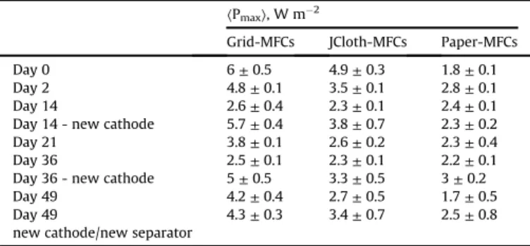
Average maximum power densities of SEA-MFCs over time. Maximum power den-sity values were extracted from the power curves.
〈Pmax〉, W m "2
Grid-MFCs JCloth-MFCs Paper-MFCs Day 0 6 ± 0.5 4.9 ± 0.3 1.8 ± 0.1 Day 2 4.8 ± 0.1 3.5 ± 0.1 2.8 ± 0.1 Day 14 2.6 ± 0.4 2.3 ± 0.1 2.4 ± 0.1 Day 14 - new cathode 5.7 ± 0.4 3.8 ± 0.7 2.3 ± 0.2 Day 21 3.8 ± 0.1 2.6 ± 0.2 2.3 ± 0.4 Day 36 2.5 ± 0.1 2.3 ± 0.1 2.2 ± 0.1 Day 36 - new cathode 5 ± 0.5 3.3 ± 0.5 3 ± 0.2 Day 49 4.2 ± 0.4 2.7 ± 0.5 1.7 ± 0.5 Day 49
new cathode/new separator
Current-potential curves showed an improvement in the air-cathode kinetics while the bioanode kinetics remained stable (Fig. 3C). It can be guessed that the hydrophobicity of the baking paper impeded the initial performance by slowing down the arrival of the electrolyte at the cathode. It took some time for the air-cathode to reach optimal wetting. Progressive wetting of the cathode then resulted in higher power production at day 2.
Despite the clear improvement from day 0 to day 2, the cathode kinetics of the Paper-SEAs remained significantly less efficient than those of the Grid-SEAs and JCloth-SEAs. The possibility of an impediment of HO"
ion transfer[34,35]by the paper separator was investigated. HO"
mass transfer coefficients through J-cloth and paper were determined experimentally in abiotic conditions. The OH"
mass transfer coefficient through paper (8.35 % 10"10m s"1) was considerably lower than that through the three layers of J-cloth as used in the SEA (1.52 % 10"5m s"1
). These results confirmed that the paper separator hindered the transfer of the HO"
ions produced by the oxygen reduction reaction:
O2 þ 4H2O þ 4e"/ 4HO" (2)
The resulting alkalinization in the vicinity of the cathode was thermodynamically detrimental to the oxygen reduction reaction. From day 2 to day 14, the Paper-SEAs displayed quite steady performance (Fig. 2,Table 1). Anodes stayed stable and current-potential curves of the air-cathode showed only a minor decrease (Fig. 3C). Compared to the Grid-SEAs and JCloth-SEAs, the Paper-SEAs ensured lower but more stable performance. By hindering the OH"
transfer, the paper separator impeded the air-cathode ki-netics but, in return, the paper separator protected the air-cathodes from kinetic deterioration. Furthermore, the paper separator also had a stabilizing effect on the bioanode kinetics, probably by
decreasing the parasitic mass transfer of oxygen from the cathode to the bioanode.
At day 14, the air-cathodes were removed and their surfaces were imaged by epifluorescence microscopy to characterize biofouling (Fig. 4). As anticipated, the air-cathodes of the Grid-SEAs showed a strong presence of microorganisms as a compact biofilm on the surface (Fig. 4A). The role of the plastic grid was only to prevent an electrical short-circuit between the anode and cathode and not to protect the air-cathode from biofouling. Logically, the air-cathode from the Grid-SEAs showed dense biofouling. Micro-organisms were also present on the cathodes of the JCloth-SEAs and the Paper-SEAs but in smaller amounts (Fig. 4B and C). There was no significant difference in microbial colonization between the air-cathodes coming from the JCloth-SEAs and the Paper-SEAs. The three layers of J-cloth and the paper both protected the air-cathodes from microbial colonization to a similar extent.
At day 14, all SEAs had their air-cathode replaced by a new one. The reactor design allowed this operation to be performed without draining the electrolyte. Immediately, the power densities increased to as high as 6 W m"2and 4.55 W m"2(5.7 ± 0.4 and 3.8 ± 0.7 W m"2 on average) for Grid-SEAs and JCloth-SEAs respectively (Fig. 2D). The Paper-SEAs maintained almost stable performance after air-cathode replacement (2.3 ± 0.7 W m"2on average). A comparison of the current-potential curves recorded just before and 2 h after the change of air-cathodes, showed that the bioanode kinetics were not affected by the operation (Fig. 3). The capacity of the design proposed here to enable the air-cathode of a SEA to be replaced without impacting the bioanode was fully confirmed. It can thus be concluded that the immediate increase in MFC performance was exclusively due to the air-cathode (Fig. 3).
Form day 14 to day 36 (Table 1), the performance of Grid-SEAs decreased over time. The current-potential curves (data not
shown) indicated that the performance loss was due to combined bioanode and air-cathode kinetics deterioration. The performance of JCloth-SEAs also fell over time but, in this case, the performance loss was mostly due to deterioration of the bioanode kinetics. The Paper-SEAs gave the most stable performance. The current-potential curves showed that, as observed from day 0 to day 2, the new air-cathodes firstly showed slightly lowered performance, which increased after a few days. This behaviour confirmed some hindrance of the electrolyte transfer through the paper, which delayed air-cathode wetting.
Air-cathodes were replaced a second time at day 36. All MFCs provided increased performance after having their air-cathodes changed (Table 1; power curves in Supplementary Data, Fig. 3). As previously, the current-potential curves recorded just before and just after the air-cathode replacement (Supplementary Data,Fig. 3) indicated that the bioanodes were not impacted by the operation. Just after the change of air-cathodes, the maximum power densities were 16% and 31% lower than the initial values (day 0) for the Grid-SEAs and the JCloth-Grid-SEAs, respectively, while the Paper-SEA reached its maximum power of 3.01 W m"2. At day 49, the air-cathodes were replaced once again and the J-Cloth and paper separators were also replaced at the same time. The maximum power densities were 28% and 30% lower than the initial values (day 0) for the Grid-SEAs and the JCloth-SEAs. This slow perfor-mance loss that was not compensated by air-cathode replacement indicated a slow decrease of the bioanode performance. Changing the J-Cloth and paper separators did not have any clear impact, indicating that the transfer capacity of the separators was not affected by seven weeks of operation. J-cloths presented a brown aspect and imaging by epifluorescence microscopy showed full coverage of the fibres on both faces by bacteria. Papers also showed high microbial colonization, on either side (Fig. 4).
From a practical standpoint, it can be summarized that, with two successive air-cathode replacements, it was possible to obtain power densities ranging from 2.5 to 6.0 W m"2with the Grid-SEAs,
from 2.2 to 4.9 W m"2 with the JCloth-SEAs and from 1.7 to 3.0 W m"2 with the Paper-SEAs. The Paper-SEAs produced the lowest power but had the most stable performance.
The internal ionic resistance of the SEAs (RS) was measured by galvano-electrochemical impedance spectroscopy measurements. The RSparameter is the sum of the all the resistances to ion motion
between anode and cathode, i.e. the resistances to ion motion through the anodic biofilm, the electrolyte including the separator and the fouling layer of the cathode if there was one. Measurements were made on six different days including just before and just after replacement of the air-cathodes (day 36) and just before and just after replacement of the air-cathode and the separator (day 49). Whatever the separator type, SEA ionic resistance remained stable over time, with average values of 3.4 ± 0.3, 2.5 ± 0.3 and 2.7 ± 0.3
U
for the Grid-, JCloth- and Paper-SEAs, respectively. The ionic re-sistances of all the SEAs were of the same order of magnitude, slightly higher with the grid than the other two separators, prob-ably because the plastic grids mechanically masked a part of the cross sectional area. The large opening of the J-cloth and paper pores (Fig. 4) explained these separators did not induce a higher resistance to ion transfer than that of the electrolyte. Consequently, the values of the internal ionic resistance did not explain the significantly higher performance obtained with the Grid-MFCs than with the other separators. Another cause had to be sought.
The SEA ionic resistance was never perturbed by biofouling. In particular, the resistances of the SEAs after 49 days of operation were similar to those measured after replacing the separators by new ones. The ion transfer rates, globally measured by the RS parameter, were consequently not affected by the biofouling, although considerable biofilm development was observed on the separator and the air-cathode surfaces. It can be concluded that fouling or biofouling did not impact the air-cathode kinetics by decreasing the rate of ion transfers. The most likely explanation is that (bio-)fouling impacted the air-cathode kinetics by inhibiting the catalytic properties of the platinum catalyst [36]. This
assumption explains why the inhibiting effect was so great right from the first days, as observed here between day 0 and day 2, and as already reported recently[29]. The inhibition of the air-cathode was not due to continuous clogging of the separator pores by mi-crobial colonization but by fast inhibition of the platinum catalyst.
3.3. Microbial communities
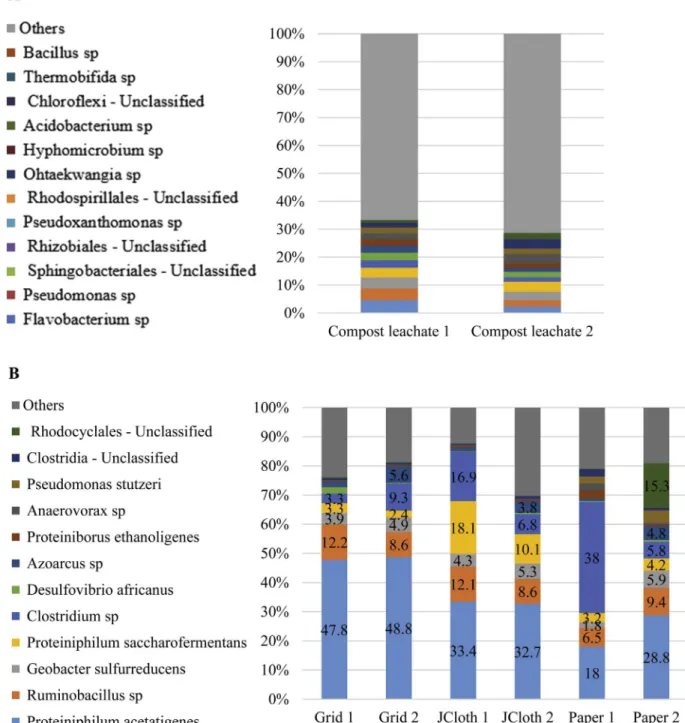
After the 49 days of MFC operation, the bioanode microbial communities were identified (Fig. 5). Compared to the compost leachate medium that was used as the initial inoculum, a strong selection of microorganisms was observed whatever the separator type. For each sample, at least 60% of the bacterial community was
identified at the species level. The duplicates, which were fairly reproducible, indicated that the nature of the separator impacted the microbial community. Grid-SEAs and JCloth-SEAs led to nicely reproducible duplicates that presented strong similarities, partic-ularly with the dominance of Proteiniphilum acetatigenes. The Paper-SEA bioanodes presented a similar pattern but were less reproducible. Some species identified here have already been met in bioanodes. Several Clostridium species have been previously detected in MFCs[37,38]and some of them have been reported to be electroactive[39]. Nevertheless, in MFCs formed in forest soil
Clostridia were found to colonize to a greater extent the anode
surface of the MFCs that produced lower power[40]. The possible electroactivity of Clostridia cannot be absolutely ensured. In
Fig. 5. Major bacterial species in percentage of the total population of (A) compost leachate medium, (B) SEA bioanodes. Species detected at less than 2% in all bioanodes were classified as “Others”.
contrast, electroactivity of Geobacter sulfurreducens is well estab-lished and it was present here in all bioanodes, but always at a percentage not exceeding 6%.
To the best of our knowledge, many species, which were present here at significant proportions, have not been detected so far among the major species of microbial anodes. The most surprising was the large proportion of Proteiniphilum acetatigenes, which made up a high percentage of the microorganisms present in all bioanodes and was the most abundant species for 5 bioanodes. Furthermore, neither the Proteiniphilum acetatigenes species nor the Proteiniphilum genus were detected in the initial compost leachate. The same situation occurred for the Ruminobacillus sp., which appeared as the second most abundant species in several bioanodes and was below the detection threshold in the initial compost leachate. The presence of such high proportions of
Pro-teiniphilum acetatigenes and Ruminobacillus sp in the bioanode
communities was consequently the result of strong selection. These species are not known for its anode-respiring capability. To the best of our knowledge, the Proteiniphilum genus has been detected in the microbial community of a biocathode that achieved reduction of p-nitrophenols[41]but not in microbial anodes, at least not in considerable proportions. In contrast, Proteiniphilum acetatigenes is well-known in the domain of waste water treatment as it can be used for bioaugmentation of sewage sludge to improve the removal of polycyclic aromatic hydrocarbons[42,43] Finally, it should be noticed that all the species identified were anaerobic. Aerobic species might be present among unclassified species, but it can be concluded that all bioanodes were satisfactory protected from ox-ygen crossover, even in the Grid-SEAs.
4. Discussion
The main objective usually evoked when implementing SEA is to decrease the anode-cathode distance in order to reduce the inter-nal resistance. Decreasing the distance that ions must cover to carry the current through the electrolyte is a major objective, particularly because MFCs and the other related electro-microbial technologies generally implement electrolytes with low ionic conductivity[23]. Nevertheless, it is commonly believed that the bioanode cannot be too close to an air-cathode because the flux of oxygen that passes through the air-cathode inhibits and/or deteriorates the bioanode. In the presence of oxygen, the strictly anaerobic electroactive bacteria are blocked and the electroactive bacteria able to work with oxygen are diverted from using the anode as the electron acceptor. In addition, the presence of oxygen favours the growth of non-electroactive bacteria in the bioanode microbial community. In all cases, the presence of oxygen on the bioanode is detrimental to its performance. It has been observed that an anode-cathode dis-tance of 1e2 cm is optimal to ensure the shortest possible ionic path length while keeping the bioanode far enough away from the oxygen flux[8,19e21]. For this reason, it is commonly thought that a separator is needed in an SEA to reduce the anode-cathode dis-tance to the millimetre scale while protecting the bioanode from oxygen crossover.
In this context, the high power densities obtained here by using the grid as the separator, which provided no protection against oxygen crossover, were surprising. The only role of the grid was to keep an anode-cathode distance of around 4 mm in order to avoid short-circuiting by small lengths of yarn that might dissociate from the carbon cloth weft. Such a problem has been observed with anode bristles[25]when too thin a carbon cloth was used as the separator. The distance of 4 mm for an SEA was consistent with those reported in the literature, which can reach 5.5 mm with glass fibre separator for instance[26].
The maximum power density reached here with the grid
separator was 6.4 W m"2and the average was 6 ± 0.5 W m"2at day 0. It was 5.7 ± 0.4 and 5 ± 0.5 W m"2at days 14 and 36 respectively, after the air-cathode had been changed. These values were higher than the highest power densities reported so far, which are around 4.7 W m"2[10]. It has been claimed recently[44]that the highest power density reported with SEA was of the order of 4.3 W m"2 [24]. The reasons why a grid used as the separator led to such high performance in comparison with the state of the art are discussed below.
It is noteworthy that the power density produced depended directly on the separator nature in the order Grid > Jcloth > Paper. The grid always led to significantly higher power density than J-cloth, although they had similar ionic resistance (3.4 ± 0.3 and 2.5 ± 0.3
U
, respectively). Looking at the SEA internal resistance was consequently not a promising approach to explain the high per-formance of the Grid-SEAs.J-cloth constituted a low, but significant, hindrance to OH"
mass transfer and the paper hindered OH"
mass transfer more strongly, as indicated by the kOH-measurements. Hindrance to OH"diffusion was in the order Grid < J-cloth < Paper. The three SEA types consequently operated under different pH conditions. In all cases, OH"
ions were produced at the cathode:
2 O2 þ 8 H2O þ 8e"/ 8 HO" (3)
and protons at the anode:
CH3COO" þ 4 H2O/2 HCO"3 þ 9 Hþ þ 8e" (4)
A bioanode tends to acidify locally, which is detrimental to its kinetics because electroactive bacteria are inhibited by pH slightly lower than neutrality [45]. In parallel, an air-cathode tends to alkalinize, which is thermodynamically detrimental and may also favour the precipitation of mineral hydroxides[35]. Avoiding bio-anode acidification[45] and cathode alkalinization[35]is a key issue in the optimization of MFC operation[44].
Here, between the anode that produced protons and the cath-ode that produced OH"
, it can be guessed easily that the pH gradient was the lowest in the Grid-SEAs, which permitted free diffusion and migration of the buffering species through the large grid mesh. The distance between anode and cathode was short and diffusion was not hampered between them. This was the best possible situation to balance the internal pH of the SEA and miti-gate both bioanode acidification and cathode alkalinization. In contrast, the paper constituted a low but significant barrier to OH"
transfer. It was observed that this barrier hampered the cathode performance. The J-cloth had a median position on the scale of diffusion hindrance. The remarkably high performance achieved with the Grid-SEAs can be attributed to the optimal pH balance inside the SEA. The lower performance levels obtained with JCloth-SEAs and Paper-JCloth-SEAs were probably related to the increasing bar-rier to diffusion of the buffering species. The different pH situations may also explain the difference in microbial communities depending on the nature of the separator.
The effects of migration and diffusion on pH balance can be assessed theoretically[23]. The electrolyte was mainly composed of KCl 60 mM, NaHCO3buffer 50 mM, NaH2PO420 mM and sodium
acetate 20 mM, which corresponded, at pH 7.0, to the transport numbers reported inTable 2.
In the absence of diffusion and convection, when migration is the only motor of mass transfer, transport numbers give the contribution of each ion type to current transport through the electrolyte. Here the transport numbers indicate that, in the absence of diffusion, 86.3% of the current would be transported through the electrolyte by the motion of the Kþ
, Naþ
and Cl"
The buffering species were consequently weakly moved by migration. This assumption was confirmed by calculating the mo-lecular flux of each ion. Momo-lecular fluxes were obtained by dividing the transport numbers by the ion charge (for theoretical details see Ref.[23]).
A balance can be drawn up on the basis of 100 electrons exchanged. For 100 electrons exchanged, 100 OH"
ions are pro-duced at the cathode (Equation(3)) and 112.5 protons are produced at the anode (Equation(4)). In this context, migration inside the SEA contributed to pH balance only by the motion of 2.83 HPO4
2-ions towards the anode. These fluxes were clearly not sufficient to balance the production of 112.5 protons. Migration did not ensure pH balance inside the SEA. Consequently, pH gradients were established inside the SEA by accumulation of the acidic form of the buffering (H2CO3, H2PO4") close to the anode surface and the
alka-line forms (HCO3", HPO42-) close to the cathode surface, and pH
balance was mainly achieved by gradient-driven diffusion of the buffering species.
Local pH is the main parameter that controls the electrode ki-netics. The present studies confirmed the main importance of pH balance in controlling MFC performance[23,44,46]. Here, migra-tion helped to mitigate the bioanode acidificamigra-tion and the cathode alkalinization only to a minor extent. pH balance was mainly ensured by the diffusion of buffering species. This situation ex-plains why J-cloth had a detrimental effect on MFC performance with respect to the grids although both separators displayed similar internal resistance. The internal ionic resistance is related to migration, while diffusion was the key process ensuring pH balance inside the SEA.
This theoretical approach put in light the crucial role of the pH balance and how it can simply explain the better performance obtained with the grid separator. Controlling and improving pH balance between the bioanode and the cathode should be a major way to go ahead in increasing the performance of MFCs and particularly SEAs. In this way, implementing microelectrodes to measure the local pH values inside SEAs should be a helpful experimental support.
The grid separator was the most efficient in letting buffering compounds diffuse freely. This is an extremely simple and efficient solution to achieve pH balance inside the SEA. In return, it could be feared that the bioanode may not be protected against oxygen diffusion from the cathode. Actually, most bioanodes implemented with the grid and J-cloth separators presented a shift towards positive values (3 out of 4 after 14 days), while this was not observed with the Paper-SEAs. This shift may have been due to oxygen crossover, which resulted in a mixed potential [33]. Nevertheless, identification of the microbial communities showed that all bioanodes without exception presented a large percentage of anaerobic species. It can be guessed that oxygen crossover was mitigated by the combination of three virtuous effects. Firstly, epifluorescence microscopy showed the presence of
microorganisms on the cathode surface, with greater biofilm coverage in the case of the grid separator. These microorganisms most likely helped to consume the oxygen that crossed the air-cathode. Secondly, thanks to its 3-dimensional structure, the bio-anode had a larger active surface area than the cathode. The cath-ode was thus forced to work at high current density and consequently to consume a large proportion of the oxygen flux that crossed it. Thirdly, the 3-dimensional structure of the bioanode should allow aerobic species to develop on small parts of the electrode against the separator. The aerobic patches remained restricted to a small percentage of the anode surface area, so aer-obic species were not among the most abundant species of the bioanode community. Such growth of protective aerobic species has already been suspected when 3-dimensional brush bioanodes were set too close to air-cathodes [8]. In the case of flat 2-dimensional bioanodes, such a parasitic aerobic growth would severely hamper the MFC performance. Here, the 3-dimensional structure may have accepted minor aerobic patches.
These remarks suggest two possible ways to improve the Grid-SEA design by mitigating oxygen crossover. Favouring the forma-tion of an aerobic biofilm as close as possible to the cathode surface could be a promising solution, and has already been proposed under the name of “microbial separator” [23]. The present data confirm the interest of this option by showing that the formation of a biofilm was not a cause of deterioration of the cathode kinetics. Secondly, cell design and operational strategy may be chosen in order to force the cathode to work at high current density and thus consume as much oxygen as possible, reducing the remaining flux to the bioanode. A 3-dimensional bioanode, as used here, is a suitable design for this purpose. It may also be advisable to work at high current rather than high voltage or maximum power. The commercial interest of working at high current to protect the bio-anode against oxygen crossover, rather than working at maximum power, should be further investigated by comparing the efficiency of the whole system including the appropriate electronic control devices.
The paper separator led to modest performance, which never exceeded 3.2 W m"2(day 16). The paper separator delayed cathode wetting and affected the cathode kinetics by hampering the pH balance. Nevertheless, the paper separator kept the bioanodes and air-cathodes fairly stable over time compared to the other two separators. Bioanodes were protected against oxygen crossover, so the shift towards positive potentials observed with most of the bioanodes used with the grid or J-cloth separators did not occur with paper. The paper separator also delayed the air-cathode in-hibition, although it did not significantly impact the cathode biofouling in comparison to the J-cloth separator. Formation of the biofilm on the cathode surface was similar with J-cloth and paper separators. In contrast, the visual aspect of the silicon foils used during the bioanode preparation phase showed that the paper considerably protected the foil against fouling, to a greater extent
Table 2
Concentration, transport numbers (ti) and molecular fluxes of the major ions contained in the electrolyte (pH 7.0). The molecular fluxes were calculated on the basis of 100
electrons exchanged at the electrodes.
Species Concentration (mol L"1) t
i%100 (percentage) Molecular fluxes (molecule/100 electrons) Hþ 10e7 2.17 % 10"4 2.17 % 10"4 HO" 10e7 1.23 % 10"4 1.23 % 10"4 HCO3" 0.048 0.28 0.28 Kþ 0.06 27.38 27.38 Cl" 0.06 28.43 28.43 H2PO4 " 0.012 2.68 2.68 HPO42- 0.008 5.66 2.83 CH3COO" 0.02 5.08 5.08 Naþ 0.1 30.49 30.49
than J-cloth did. It can consequently be assumed that the paper separator stabilized the cathode kinetics by mitigating fouling rather than biofouling. These data tend to confirm the higher impact of surface fouling rather than biofouling on cathode per-formance, which has been suggested from the analysis of cathode surface deposits[47].
The study also provided evidence of a stringent selection of
Proteiniphilum species, which were heavily dominant in the more
efficient MFCs, particularly Proteiniphilum acetatigenes. The ratio of this species depended on the kind of separator and increased with the MFC performance. This species would deserve further study to confirm its possible high electroactivity. The presence of a low percentage of Geobacter sulfurreducens in all the bioanodes makes us wonder whether P. acetatigenes is electroactive by itself or whether it works in synergy with G. sulfurreducens. P. acetatigenes is known for its capability to enhance the removal of polycyclic aro-matic hydrocarbons in wastewater treatment[42,43]. The strong selection observed here from an initial medium where this species was not detected is an additional point of interest of the study. It may open up a new avenue for the formation of bioanodes dedi-cated to wastewater treatment. It also points to the interest of the microbial richness of soils[40,48]as a source of efficient electro-active biofilms that is far from being fully exploited so far.
Finally, the original SEA design proposed here, which included a removable air-cathode, proved to be fully efficient. The 18 re-placements of air-cathodes (at days 14, 36 and 49) were performed without draining the electrolyte or disturbing the bioanode ki-netics. In each case, the air-cathode replacement was immediately followed by an increase in the MFC performance. This strategy allowed the bioanodes to be optimally exploited, e.g. by boosting the power density of Grid-MFCs to above 4 W m"2after 7 weeks of operation.
5. Conclusion
Power densities higher than those reported so far, up to 6.4 W m"2, were produced with SEAs using an open grid as the
separator. The sole function of this separator was to avoid electrical short-circuiting between anode and cathode while leaving the widest possible space for the free transport of all species. The excellent results obtained with such a simple configuration were explained by at least three reasons: i) The essential importance of pH balance; free diffusion of all species through the large-mesh grid was the best situation to mitigate acidification of the bioanode and alkalinization of the air-cathode; ii) the grid did not hinder oxygen crossover but the 3-dimensional structure of the bioanode might accept the occurrence of aerobic patches, which consumed oxygen and protected the dominant anaerobic microbial species; more-over, oxygen crossover was probably mitigated by the development of an aerobic biofilm on the cathode surface; iii) using a removable cathode was the third major reason for the good performance ob-tained here. It allowed the early inhibition of the cathode kinetics to be overcome. Although it cannot be an economically-sustainable strategy, the removable cathode design succeeded in revealing the full performance of SEAs.
Finally, the strong selection of Proteiniphilum acetatigenes is an intriguing issue. The high, and reproducible, ratios observed in the best performing SEAs cannot be fortuitous, and the mechanisms of its contribution to electroactivity deserves further basic studies, in particular because of its possible interest for wastewater treatment. Acknowledgements
This work benefited from the support of the French state, managed by the Agence Nationale de la Recherche (ANR), within
the framework of the Bioelec project (ANR-13-BIME-006). The au-thors acknowledge the LGC workshop for manufacturing the MFC and SEA devices under the guidance of Alain Müller and Vincent Loisel. The authors also greatly appreciated the help of Marie-Line De Solan (LGC-INPT) for SEM imaging, of Sophie Pecastaings (PhD) and Alexis Simons (PhD student) for ADN extraction. Appendix A. Supplementary data
Supplementary data related to this article can be found athttp:// dx.doi.org/10.1016/j.jpowsour.2017.03.016.
References
[1]D. Pant, G. Van Bogaert, L. Diels, K. Vanbroekhoven, A review of the substrates used in microbial fuel cells (MFCs) for sustainable energy production, Bio-resour. Technol. 101 (2010) 1533e1543.
[2]P. Pandey, V.N. Shinde, R.L. Deopurkar, S.P. Kale, S.A. Patil, D. Pant, Recent advances in the use of different substrates in microbial fuel cells toward wastewater treatment and simultaneous energy recovery, Appl. Energy 168 (2016) 706e723.
[3]Y. Ye, X. Zhu, B.E. Logan, Effect of buffer charge on performance of air-cathodes used in microbial fuel cells, Electrochim. Acta 194 (2016) 441e447. [4]A.P. Borole, G. Reguera, B. Ringeisen, Z.-W. Wang, Y. Feng, B.H. Kim,
Electro-active biofilms: current status and future research needs, Energ. Environ. Sci. 4 (2011) 4813e4834.
[5]D. Pocaznoi, B. Erable, L. Etcheverry, M.-L. Delia, A. Bergel, Towards an engineering-oriented strategy for building microbial anodes for microbial fuel cells, Phys. Chem. Chem. Phys. 14 (2012) 13332e13343.
[6]M. Rimboud, D. Pocaznoi, B. Erable, A. Bergel, Electroanalysis of microbial anodes for bioelectrochemical systems: basics, progress and perspectives, Phys. Chem. Chem. Phys. 16 (2014) 16349e16366.
[7]F.J. Hernandez-Fernandez, A. Perez de los Rios, M.J. Salar-Garcia, V.M. Ortiz-Martinez, L.J. Lozano-Blanco, C. Godinez, et al., Recent progress and perspec-tives in microbial fuel cells for bioenergy generation and wastewater treat-ment, Fuel Process. Technol. 138 (2015) 284e297.
[8]B.E. Logan, M.J. Wallack, K.-Y. Kim, W. He, Y. Feng, P.E. Saikaly, Assessment of microbial fuel cell configurations and power densities, Environ. Sci. Technol. Lett. 2 (2015) 206e214.
[9]Y. Fan, E. Sharbrough, H. Liu, Quantification of the internal resistance distri-bution of microbial fuel cells, Environ. Sci. Technol. 42 (2008) 8101e8107. [10] W. Yang, B.E. Logan, Immobilization of a metal-nitrogen-carbon catalyst on
activated carbon with enhanced cathode performance in microbial fuel cells, Chemsuschem 9 (2016) 2226e2232.
[11] C. Santoro, S. Babanova, P. Atanassov, B. Li, I. Ieropoulos, P. Cristiani, High power generation by a membraneless single chamber microbial fuel cell (SCMFC) using enzymatic bilirubin oxidase (BOx) air-breathing cathode, J. Electrochem. Soc. 160 (2013) H720eH726.
[12] T. Ewing, P.T. Ha, J.T. Babauta, N.T. Tang, D. Heo, H. Beyenal, Scale-up of sediment microbial fuel cells, J. Power Sources 272 (2014) 311e319. [13] W.-W. Li, H.-Q. Yu, Stimulating sediment bioremediation with benthic
mi-crobial fuel cells, Biotechnol. Adv. 33 (2015) 1e12.
[14] R. Rousseau, X. Dominguez-Benetton, M.-L. Delia, A. Bergel, Microbial bio-anodes with high salinity tolerance for microbial fuel cells and microbial electrolysis cells, Electrochem. Commun. 33 (2013) 1e4.
[15] R. Rousseau, C. Santaella, W. Achouak, J.-J. Godon, A. Bonnafous, A. Bergel, et al., Correlation of the electrochemical kinetics of high-salinity-tolerant bio-anodes with the structure and microbial composition of the biofilm, Chem-electrochem 1 (2014) 1966e1975.
[16] M. Grattieri, M. Suvira, K. Hasan, S.D. Minteer, Halotolerant extremophile bacteria from the Great Salt Lake for recycling pollutants in microbial fuel cells, J. Power Sources 356 (2016) 310e318,http://dx.doi.org/10.1016/ j.jpowsour.2016.11.090.
[17] R. Karthikeyan, A. Selvam, K.Y. Cheng, J.W.-C. Wong, Influence of ionic con-ductivity in bioelectricity production from saline domestic sewage sludge in microbial fuel cells, Bioresour. Technol. 200 (2016) 845e852.
[18] N. Jannelli, R.A. Nastro, V. Cigolotti, M. Minutillo, G. Falucci, Low pH, high salinity: too much for microbial fuel cells? Appl. Energy (2016) http:// dx.doi.org/10.1016/j.apenergy.2016.07.079. Available online 3 August 2016, ISSN 0306-2619.
[19] S. Cheng, H. Liu, B.E. Logan, Increased power generation in a continuous flow MFC with advective flow through the porous anode and reduced electrode spacing, Environ. Sci. Technol. 40 (2006) 2426e2432.
[20] Y. Fan, H. Hu, H. Liu, Enhanced coulombic efficiency and power density of air-cathode microbial fuel cells with an improved cell configuration, J. Power Sources 171 (2007) 348e354.
[21] J.M. Moon, S. Kondaveeti, T.H. Lee, Y.C. Song, B. Min, Minimum interspatial electrode spacing to optimize air-cathode microbial fuel cell operation with a membrane electrode assembly, Bioelectrochemistry 106 (2015) 263e267. [22] X. Zhang, S. Cheng, P. Liang, X. Huang, B.E. Logan, Scalable air cathode
microbial fuel cells using glass fiber separators, plastic mesh supporters, and graphite fiber brush anodes, Bioresour. Technol. 102 (2011) 372e375. [23] M. Oliot, S. Galier, H. Roux de Balmann, A. Bergel, Ion transport in microbial
fuel cells: key roles, theory and critical review, Appl. Energy 183 (2016) 1682e1704.
[24] Y. Fan, S.-K. Han, H. Liu, Improved performance of CEA microbial fuel cells with increased reactor size, Energy Environ. Sci. 5 (2012) 8273e8280. [25] Y. Ahn, B.E. Logan, A multi-electrode continuous flow microbial fuel cell with
separator electrode assembly design, Appl. Microbiol. Biotechnol. 93 (2012) 2241e2248.
[26] V. Yousefi, D. Mohebbi-Kalhori, A. Samimi, M. Salari, Effect of separator electrode assembly (SEA) design and mode of operation on the performance of continuous tubular microbial fuel cells (MFCs), Int. J. Hydrog. Energy 41 (2016) 597e606.
[27] S. Hays, F. Zhang, B.E. Logan, Performance of two different types of anodes in membrane electrode assembly microbial fuel cells for power generation from domestic wastewater, J. Power Sources 196 (2011) 8293e8300.
[28] F. Zhang, X. Xia, Y. Luo, D. Sun, D.F. Call, B.E. Logan, Improving startup per-formance with carbon mesh anodes in separator electrode assembly microbial fuel cells, Bioresour. Technol. 133 (2013) 74e81.
[29] M. Oliot, L. Etcheverry, A. Bergel, Removable air-cathode to overcome cathode biofouling in microbial fuel cells, Bioresour. Technol. 221 (2016) 691e696. [30] B. Cercado, N. Byrne, M. Bertrand, D. Pocaznoi, M. Rimboud, W. Achouak, et al.,
Garden compost inoculum leads to microbial bioanodes with potential-independent characteristics, Bioresour. Technol. 134 (2013) 276e284. [31] Y. Liu, F. Harnisch, K. Fricke, R. Sietmann, U. Schr€oder, Improvement of the
anodic bioelectrocatalytic activity of mixed culture biofilms by a simple consecutive electrochemical selection procedure, Biosens. Bioelectron. 24 (2008) 1006e1011.
[32] E. Blanchet, E. Desmond, B. Erable, A. Bridier, T. Bouchez, A. Bergel, Compar-ison of synthetic medium and wastewater used as dilution medium to design scalable microbial anodes: application to food waste treatment, Bioresour. Technol. 185 (2015) 106e115.
[33] F. Harnisch, S. Wirth, U. Schroeder, Effects of substrate and metabolite crossover on the cathodic oxygen reduction reaction in microbial fuel cells: platinum vs. iron(II) phthalocyanine based electrodes, Electrochem. Commun. 11 (2009) 2253e2256.
[34] Y. Yuan, S. Zhou, J. Tang, In situ investigation of cathode and local biofilm microenvironments reveals important roles of OH- and oxygen transport in microbial fuel cells, Environ. Sci. Technol. 47 (2013) 4911e4917.
[35] S.C. Popat, D. Ki, B.E. Rittmann, C.I. Torres, Importance of OH- transport from cathodes in microbial fuel cells, Chemsuschem 5 (2012) 1071e1079.
[36] H. Liu, S. Cheng, L. Huang, B.E. Logan, Scale-lip of membrane-free single-chamber microbial fuel cells, J. Power Sources 179 (2008) 274e279. [37] U. Michaelidou, A. ter Heijne, G.J.W. Euverink, H.V.M. Hamelers, A.J.M. Stams,
J.S. Geelhoed, Microbial communities and electrochemical performance of titanium-based anodic electrodes in a microbial fuel cell, Appl. Environ. Microbiol. 77 (2011) 1069e1075.
[38] K. Rabaey, N. Boon, S.D. Siciliano, M. Verhaege, W. Verstraete, Biofuel cells select for microbial consortia that self-mediate electron transfer, Appl. Envi-ron. Microbiol. 70 (2004) 5373e5382.
[39] H.S. Park, B.H. Kim, H.S. Kim, H.J. Kim, G.T. Kim, M. Kim, et al., A novel elec-trochemically active and Fe(III)-reducing bacterium phylogenetically related to clostridium butyricum isolated from a microbial fuel cell, Anaerobe 7 (2001) 297e306.
[40] S.J. Dunaj, J.J. Vallino, M.E. Hines, M. Gay, C. Kobyljanec, J.N. Rooney-Varga, Relationships between soil organic matter, nutrients, bacterial community structure, and the performance of microbial fuel cells, Environ. Sci. Technol. 46 (2012) 1914e1922.
[41] L. Zhang, X. Jiang, J. Shen, K. Xu, J. Li, X. Sun, et al., Enhanced bio-electrochemical reduction of p-nitrophenols in the cathode of self-driven microbial fuel cells, Rsc. Adv. 6 (2016) 29072e29079.
[42] S.Y. Chen, X.Z. Dong, Proteiniphilum acetatigenes gen. nov., sp nov., from a UASB reactor treating brewery wastewater, Int. J. Syst. Evol. Microbiol. 55 (2005) 2257e2261.
[43] S.B. Larsen, D. Karakashev, I. Angelidaki, J.E. Schmidt, Ex-situ bioremediation of polycyclic aromatic hydrocarbons in sewage sludge, J. Hazard. Mater. 164 (2009) 1568e1572.
[44] S.C. Popat, C.I. Torres, Critical transport rates that limit the performance of microbial electrochemistry technologies, Bioresour. Technol. 215 (2016) 265e273.
[45] C.I. Torres, A.K. Marcus, B.E. Rittmann, Proton transport inside the biofilm limits electrical current generation by anode-respiring bacteria, Biotechnol. Bioeng. 100 (2008) 872e881.
[46] S.C. Popat, D. Ki, M.N. Young, B.E. Rittmann, C.I. Torres, Buffer pK(a) and transport govern the concentration overpotential in electrochemical oxygen reduction at neutral Ph, Chemelectrochem 1 (2014) 1909e1915.
[47] M. Santini, M. Guilizzoni, M. Lorenzi, P. Atanassov, E. Marsili, S. Fest-Santini, et al., Three-dimensional X-ray microcomputed tomography of carbonates and biofilm on operated cathode in single chamber microbial fuel cell, Bio-interphases 10 (2015) 31009.
[48] R.A. Barbato, K.L. Foley, J.A. Toro-Zapata, R.M. Jones, C.M. Reynolds, The power of soil microbes: sustained power production in terrestrial microbial fuel cells under various temperature regimes, Appl. Soil Ecol. 109 (2017) 14e22.