Publisher’s version / Version de l'éditeur:
Technical Note (National Research Council of Canada. Division of Building Research), 1970-06-01
READ THESE TERMS AND CONDITIONS CAREFULLY BEFORE USING THIS WEBSITE. https://nrc-publications.canada.ca/eng/copyright
Vous avez des questions? Nous pouvons vous aider. Pour communiquer directement avec un auteur, consultez la
première page de la revue dans laquelle son article a été publié afin de trouver ses coordonnées. Si vous n’arrivez pas à les repérer, communiquez avec nous à [email protected].
Questions? Contact the NRC Publications Archive team at
[email protected]. If you wish to email the authors directly, please see the first page of the publication for their contact information.
NRC Publications Archive
Archives des publications du CNRC
For the publisher’s version, please access the DOI link below./ Pour consulter la version de l’éditeur, utilisez le lien DOI ci-dessous.
https://doi.org/10.4224/20359240
Access and use of this website and the material on it are subject to the Terms and Conditions set forth at
Glass Thickness Requirements for Sealed, Double-Glazed Windows
Under Wind Pressures
Brown, W. G.
https://publications-cnrc.canada.ca/fra/droits
L’accès à ce site Web et l’utilisation de son contenu sont assujettis aux conditions présentées dans le site LISEZ CES CONDITIONS ATTENTIVEMENT AVANT D’UTILISER CE SITE WEB.
NRC Publications Record / Notice d'Archives des publications de CNRC: https://nrc-publications.canada.ca/eng/view/object/?id=0f0e6d46-8b2d-437a-b76c-579a6107799c https://publications-cnrc.canada.ca/fra/voir/objet/?id=0f0e6d46-8b2d-437a-b76c-579a6107799c
NATIONAL RESEARCH COUNCIL
OF
CANADA
DIVISION OF BUILDING RESEARC.H
'f
E
C
JHI
N II
C
AIL .
NOTJE
No.
550PREPARED BY
w.
G. Brown CHECKED BY D. G. S.APPROVEDBY N. B. H.
セ June 1970
PREPARED FOR Working Group of the Standing Cormnittee on Residential Standards
SUBJECT GLASS THICKNESS REQUIREMENTS FOR SEALED, DOUBLE-GLAZED WINDOWS UNDER ¥lIND PRESSURES.
PRELIMINARY CONSIDERATIONS
Deflections and Stresses in Single-glazed Windows
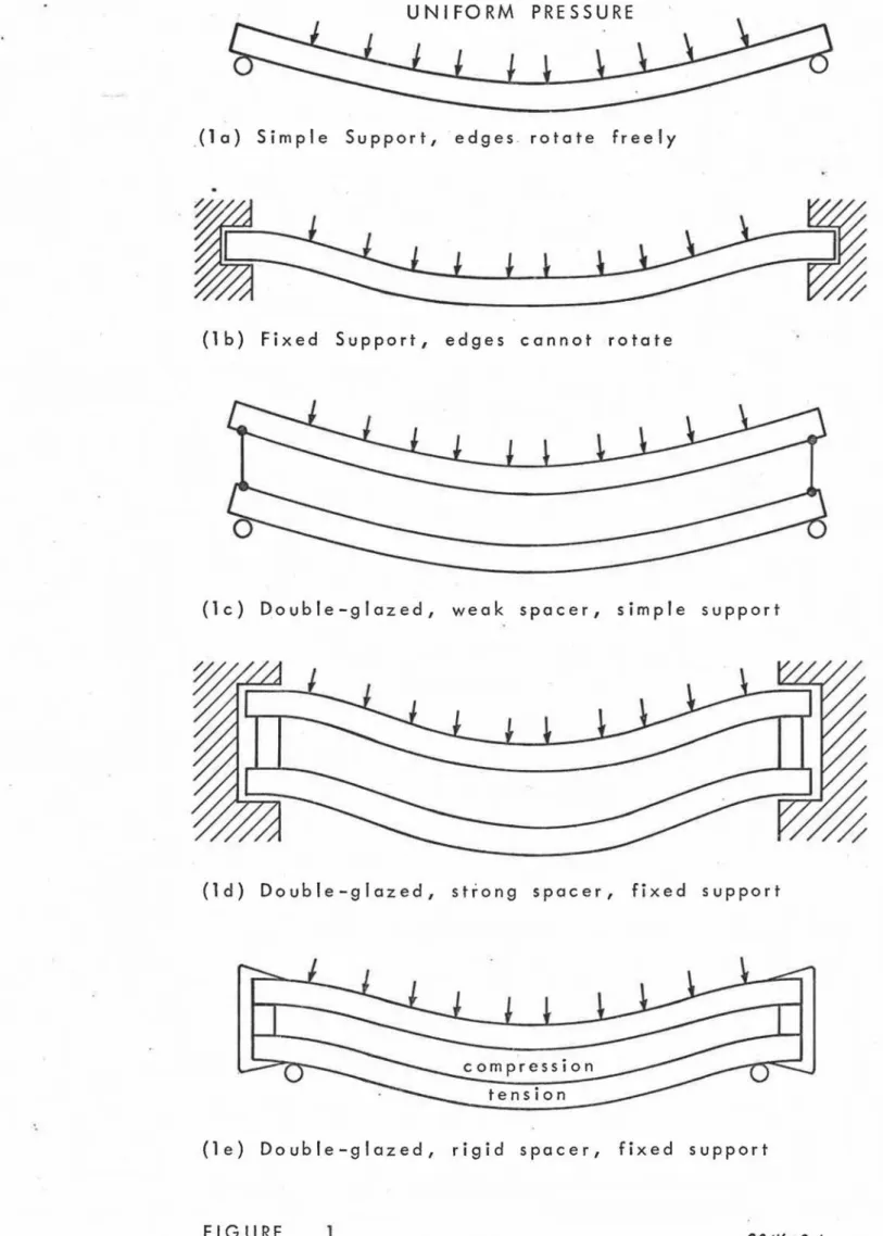
Figures 1 a and 1 b illustrate the two possible extremes of edge
support for single-glazed windows. Simple support (1 a) means that the
edge can rotate freely against t.he support and is also free to slide
in-wards as the window is pressurized. For this situation, the curvature
of the glass and the stress are greatest at the centre and it is here that
most breaks tend to occur. Fixed support (1 b) means that the window
edge cannot rotate, but is neve:rtheless free to slide as a pressure is
applied. In this case, curvature, resulting stress, and breakage are
greatest near the window edge, in contrast to the central location for simple support.
These situations apply only to very long, narrow windows. For most rectangular windows with simple support, the location of maximum stress and the origin of nlOst breaks moves progressively outward along
diagonals as the pressure on the window increases. The fixed support
condition is at present only understood for the condition of fairly small
deflections. As with the long, narrow window, the maximum stress
oc-curs approximately at the edge and at the middle of the larger side of
:e
I2
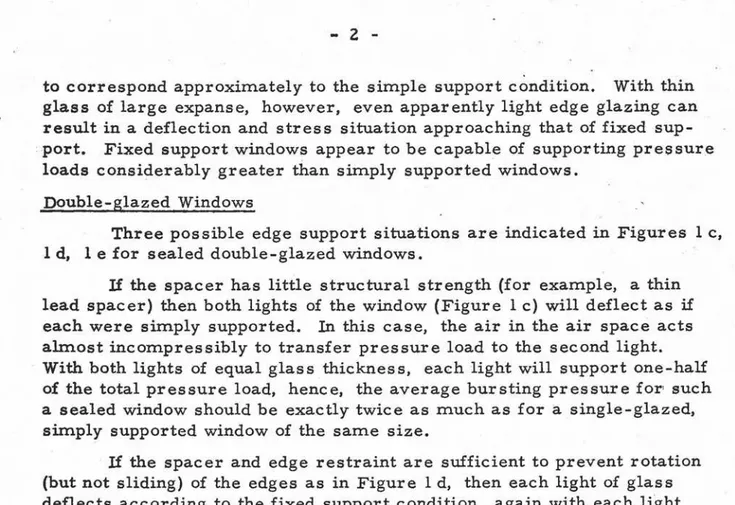
-to correspond approximately -to the simple support condition. With thin
glass of large expanse, however, even apparently light edge glazing can result in a deflection and stress situation approaching that of fixed
sup-port. Fixed support windows appear to be capable of supporting pressure
loads considerably greater than sirn.ply supported windows. Double-glazed Windows
Three possible edge support situations are indicated in Figures I c, I d, 1 e for sealed double-glazed windows.
If the spacer has little structural strength (for example, a thin
lead spacer) then both lights of the window (Figure I c) will deflect as if
each were simply supported. In this case, the air in the air space acts
almost incompressibly to transfer pressure load to the second light. With both lights of equal glass thickness, each light will support one-half of the total pressure load, hence, the average bursting pressure for' such a sealed window should be exactly twice as much as for a single-glazed, sirn.ply supported window of the same size.
If the spacer and edge restraint are sufficient to prevent rotation (but not sliding) of the edges as in Figure I d, then each light of glass deflects according to the fixed support condition, again with each light
carrying one-half of the pressure load. In this case, the average
burst-ing pressure for the sealed unit would be expected to be exactly twice as much as for a single-glazed, fixed support window of the same size.
It should not be forgotten, however, that this bursting pressure will
always be greater than obtained with simply supported windows.
Figure I e illustrates the situation that apparently occurs with
the majority of sealed, double-glazed windows. The window as a unit
is approxirn.ately sirn.ply supported, but as it deflects under the applied pressure, an additional compressive force is set up in one light and an
equal tensile force occurs in the other light. These forces restrict
rotation of the edges, with the result that for small pressures, the
de-oflections and stresses are similar to those of Figure I d even though
the window unit is not restrained in any way. As pressures are
in-creased, however, the lower glass light supports an increasingly greater
portion of the applied pressure than does the upper light. In these
circumstances, it is not possible at present to calculate the load-bearing capacity of most sealed double-glazed window units from existing data for single light, so it has been necessary to determine some bursting
strengths approximately. The available data are summarized later in
this Note.
Probability of Failure
Analysis of a great many tests on single-glazed windows with as-pect ratios of up to about 3: 1 shows that if windows are designed for a
3
-design pressure of about 0.40 of the average bursting pressure,
approxi-mately 1 per cent of the windows will fail at the design pressure.
Simi-larly, only about 0.1 per cent of the windows will fail for a design
pres-sure of O. ZO times the average bursting prespres-sure. These factors, which
are the ratio of design pressure to average bursting pressure, are
refer-red to as design factors. They can be thought of as reciprocals of safety
factors. It is customary to design windows for failure probabilities
be-tween O. 1 and 1 per cent.
In the case of sealed, double-glazed windows, the available test results are sufficient to yield the average or mean bursting strength but they are not, in themselves, sufficient to determine at what pressures
low levels of failure probability will result. For example, a set of ZO
test results gives no possible information for failure probabilities less
than 5 per cent (i. e., 1 in ZO). In this circumstance, it is necessary
to consider to what extent the design factors already established for 'single-glazing can be expected also to apply for double-'single-glazing.
Accepting that glass fails when stresses reach critical levels, it is apparent that design factors can only differ from those established for single-glazing if the relationship between stress and applied pressure
is different. It is known that for small pressures on all windows and for
all long, narrow windows, the stress varies directly with pressure. For
square single-glazing, however, in the range of pressures at which break-age occurs, it is found that the stress is approximately proportional to
the 0.75 power of pressure. This deviation from linearity which is
maxi-mal for a square plate is due to the fact that the glass acts, in part, as a
membrane. For all windows, then, stress can be expected to be
propor-tional to a power of pressure of between O. 75 and 1. O. (These two
ex-tremes are shown in Figure Z. )
From Figure Z, when stress is proportional to pressure to 0.75 power, the stress corresponding to 1 per cent probability of failure is
approximately 0.5 of the mean failure stress. If the relationship
be-. tween stress and pressure be linear, this 1 per cent probability of fail-ure stress would correspond to 0.5 times the mean bursting pressfail-ure,
so for this case, the design factor would be 0.5 rather than 0.4.
Thus it is safe to assume that the design factors that are appro-, priate for single-glazing will be conservative when used for double-glazing. AVAILABLE TEST DATA
Deflections
In order to illustrate that most sealed, double-glazed windows will be deflected and stressed as in example (e) of Figure I, some simple centre deflection measurements under uniform pressure were carried out
4
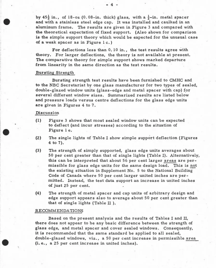
-by 45! in., of 18-oz (0. 08-in. thick) glass, with a i-in. metal spacer
and with a stainless steel edge cap. It was installed and caulked in an
aluminum frame. The results are given in Figure 3 and compared with
the theoretical expectation of fixed support. (Also shown for comparison
is the simple support theory which would be expected for the unusual case of a weak spacer as in Figure 1 c. )
For deflections less than O. 10 in., the test results agree セゥエィ
theory. For larger deflections, the theory is not available at present.
The comparative theory for simple support shows marked departure from linearity in the same direction as the test results.
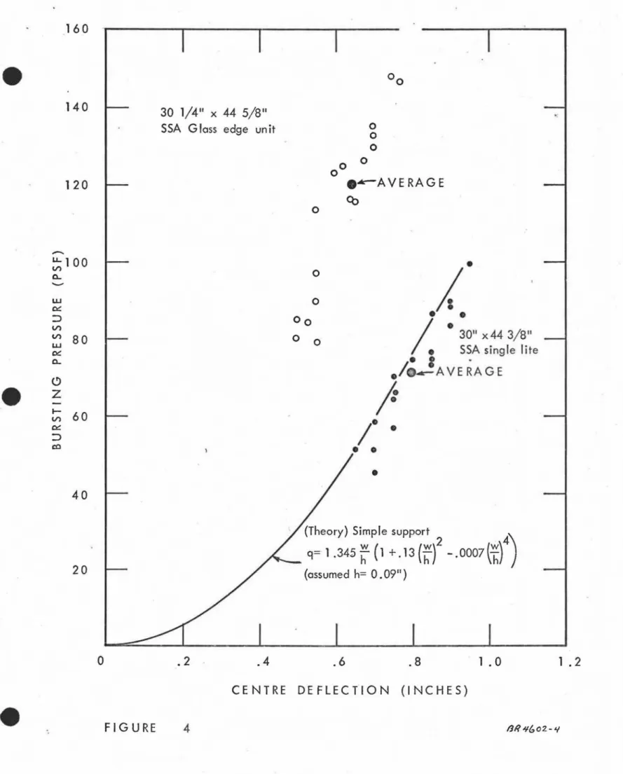
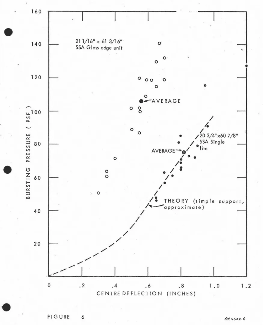
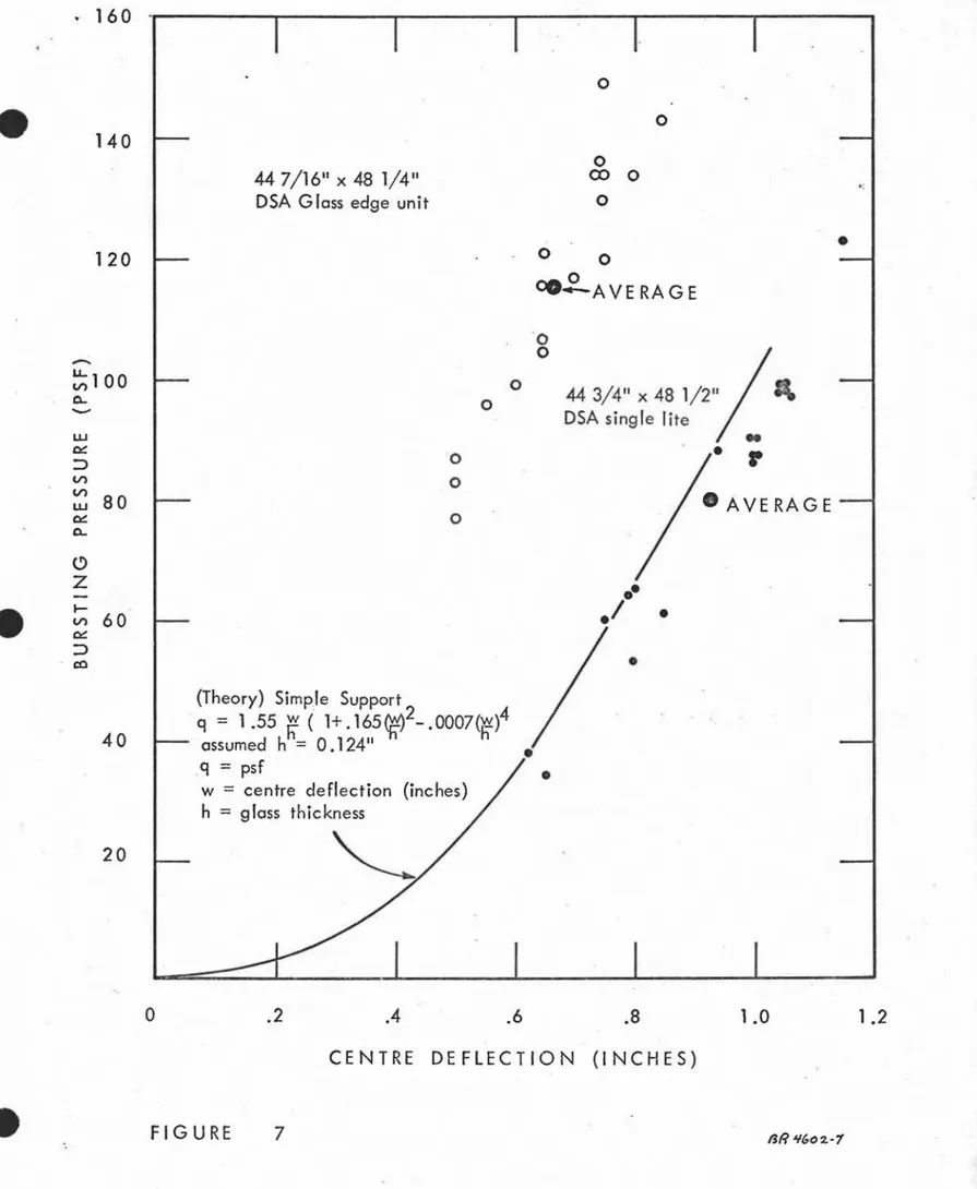
Bursting Strength
Bursting strength test results have been furnished to CMHC and to the NBC Secretariat by one glass manufacturer for two types of sealed, double-glazed window units (glass-edge and metal spacer with cap) f,or
several different window sizes. Summarized results are listed below
and pressure loads versus centre deflections for the glass edge units
are given in Figures 4 to 7.
Discussion
(1)
(2)
Figure 3 shows that most sealed window units can be expected
to deflect (and incur stresses) according to the situation of Figure 1 e.
The single lights of Table I show simple support deflection (Figures
4 to 7).
(3) The strength of simply supported, glass edge units averages about
50 per cent greater than that of single lights (Table I). Alternatively, this can be interpreted that about 56 per cent larger areas are
per-missible for glass edge units for the same design load. This is E2.t
the existing situation in Supplement No. 5 to the National Building Code of Canada where 50 per cent larger united inches are
per-mitted. Instead, the test data support an increase in united inches
of just 25 per 」・セエN
(4) The strength of m.etal spacer and cap units of arbitrary design and
edge support appears also to average about 50 per cent greater than that of single lights (Table 11 ).
RECOMMENDA TIONS
Based on the present analysis and the results of Tables I and II, there does not appear to be any basic difference between the strength of
glass edge, and metal spacer and cover sealed windows. Consequently,
it is recommended that the same standard be applied to all sealed,
double-glazed windows, viz., a 50 per cent increase in permissible area (i. e., a 25 per cent increase in united inches).
5
-Additional
Glass sizes for single lights given in the Residential Standards
have been reviewed and found to be somewhat conservative.
*
Thus,all things considered, it would appear that there should be little re-maining objection to permitting 50 per cent larger areas for (all) sealed window units.
Testing
It should be appreciated that for purposes of window strength
design, the average bursting pressure of a number of samples is not the
information that is required. What is really required is to know how
many will fail at the design load. To determine the 1 per cent failure
level for a given type of window, for example, with reasonable accuracy, would require that about 1000 samples be loaded to the design figure in
order to break about 10 samples. The results of such testing would not
offer any information about design factors and would not in themselves
permit any generalization for other types and sizes of windows. If all
of the 1000 samples were broken, then the mean bursting pressure and
design factor would be established reasonably well. Itis clear, however,
from. the section on 'probability of failure' that all of this effort would have been carried out only to establish a design factor of perhaps 0.45 in place of an estimated value of 0.4 obtained from previous tests on
single-glazing. The tests would still not allow generalizations for other
window types and sizes.
The strength of glass also depends on load duration, on
temper-ature, and to a small extent on relative humidity. These factors would
require careful attention in testing. It should also be kept in mind that
design wind pressure is a very imprecise figure, generally conservative: in this situation, high quality test results are not of great value.
In view of this, it can be expected that additional tests of the kind summarized in Tables I and II on different types of sealed-glazing
units will show the same general variability as in these Tables. Rather
than undertake any limited number of エセウエウ at this time, it would seem
more reasonable to accept the moderately well established design factors discussed under 'probability of failure' and to assume that Tables I and II are fairly characteristic of sealed double-glazing in comparison with single - glazing.
I
I
,e
TABLE I
Test Results for Glass-Edge Window Units
Average Breaking
Window Type Size, in. Number Bursting Load Ratio
of Pressure, to Single
Samples psf Light
glass-edge 30i x 44 5/8 SSA 20 120 1. 69
single light 30 x 44 SSA 19 71
-glass-edge 21 1/16 x 61 3/16 SSA 19 106 1.42
single light 20 3/4 x 607/8 SSA 18 75
-glass-edge 44 7/17 x 481. DSA4 20 115 1.44
single light 44 3/4 x 48.1 DSAa 20 80
-,
glass-edge 28 7/16 x 66 DSA 20 116 1. 76
single light 287/16 x 66 DSA 0 - 20 66
-•
TABLE II
Test Results for Metal Spacer and Cap Window Units
Average
Window Type - Size, in. Number Bursting Breaking
.
of Pressure, Load Samples psf Ratioi"
air-space 30 x 48 DS 24 144 1.3 single light 30 x 48 DS 24 108-1." air-- s pac e4 . 48 x 48 DS 20 116 2.1 single light 48 x 48 DS 25 56
-.
i"
air-space 72 x 72(i"
plate) 6 137 1.7single light 71i x 72
(i"
plate) 25 82-Notes to Tables I and II
(1) Tests for Table I were carried out in Andersen sash, which appears
to give approximately simple support in all cases. All tests were
Continuation of Notes to Tables 1 and II
(2) Tests for single lights of Table II were not contem.poraneous with
those of the double units. Slight differences in glass .thickness
re-sulting from. m.anufacture tolerance can have an appreciable effect
on bursting pressure. Edge support for the single lights for the
OS glass appears to have been interm.ediate betWeen the sim.ple
and fixed condition. The edge support for 、セオ「ャ・ZBァャ。コ・、
i>s
glassappears also to have been interm.ediate between sim.ple and fixed support, and support for the i-in. plate glass is unspecified.
UNIFORM
PRESSURE
.(10)
Simple Support, edges rotate freely(1
b) Fixed Support, edges cannot rotate(lc) Double-glazed, weak spacer, simple support
(ld) Double-glazed, strong spacer, fixed support
compression tension
(le) Double-glazed, rigid spacer, fixed support
STRESS
.;PRESSURE
Mean Bursting Pressure (MBP)t
OAMBP
O.5MBP
t
t
Mean Failure セ⦅ - - - -Stress Stress for 1%MZMMMMGセ probability af failureFIGURE
2
RE LA T ION S HIP
BET WEE N DES I G N FA C TOR AND
"
•
/
/
/
/
/
セ
.
.,
I
EX PER I MENTAL
II
セO
/
/
/
/
••
/
/
(
/
/ / / / / / / / / / /"
/..
/ /セBB
THEORY (simple support)BLLセ
"
"
" ,",,,,,,,
,..
- - " . . " " . " 151 0
-.. U-V)0
-W セ :::> V) . V) w セ0-5
o
0.10
CENTRE DEFLECTION (INCHES)
- 0.20
FIGURE 3
CENTRE DEFLECTION FOR A 33" x TUセB SEALED, DOUBLE
o
160 MキMMMMNNNNLNNNMMMセMMMMセMMM
140
120
30 1/4" x 44 5/8" SSA G loss edge un it
o
o
oo
o
0 0 e'-AVERAGEco
.;1 .2
1 .0
.8.6
.4
.2
.
o
...
lJ..100•
V) 0j
a.. ... w 0 0:: :J 00! ..
V) V) 80 0 0 30" x44 3/8" w• SSA single lite
0:: a..
•
•.il
-!AVERAGEC>
e
z
j:
I -60 V)Ie
0::•
:J co•
•
•
40(Theory) Simple support
20
アセ
1 .345
セ
(1+
.13HセIR
-
.0007セセエI
(assumed h= 0.09")CENTRE DEFLECTION (INCHES)
160
o
140
28 7/16"
x66"
DSA G lass edge un
ito
.;120
o
o
• ....-AVERAGE
000o
•
28 7/16"
x66"
DSA Single lite
a
o
o
0/
/
,.
•
I ••
/ fI_AVE RAGE
I.
f
/
.
/
/
/
/
Oセ
THEORY (Simple support,
.."""-
.
)/
approximate
/
/'
, / / ' /'"""
----",,,,,
20
40
---セ
1 00 0..-
LU 0:: ::> V) V) LU 80 0:: 0..<.?
Z セ V) 60 0:: ::> coo
. 2.4
.6
.8
1 . 01 . 2
CENTRE
DEFLECTION
(INCHES)
o
160
140
21 1/16" x 61 3/16"
SSA Glass edge unit
o
o
o
-120
o
00 0o
•
o
o
o
Nセaverageo
0o
o
o
o
\ 0/
-'
/
-
/20 3/4"x60 7/8"
_
/ . SSA Single
AVERAGE-....I
-lite
/..
•
I-• I
,
I
-/
I
I:
THEORY
(simple support,
iセ。ーーイック
imate)
/
/
/
/
/
/ '
/ ' . / . / /,....,
,...
/20
-
LL100
V) 0-... W セ ::>80
V) V) w セ 0-C) Z60
セ V) セ ::> co40
o
.2
.4
.6
.8
CENTRE DEFLECTION
(INCHES)
1 .0
1 .2
セ 160
o
o
14044 7/16
11 X48 1/4
11DSA G lass edge unit
o
ex:> 0o
120 0 0CO2-
AVE RA G E•
o·
.1
•
•
•
o
'0o
0 044 3/4"
x481/2
,1
DSA single lite
..
'0 •
r
o
(Theory) Simple Support q
=
1 .55
セ
( 1+ . 165Wl
2-NPPPWHセIT
assumed h
=
0.12411q
=
psfw
=
centre deflection (inches) h=
glass thickness 2040
-..セQ
00
0--
W セ :::> V') V')80
w セ0-0
Ze
.-
V')60
セ :::> a )o
.2
.4
.6
.8
1.0
1.2
CENTRE DEFLECTION (INCHES)