Publisher’s version / Version de l'éditeur:
Vous avez des questions? Nous pouvons vous aider. Pour communiquer directement avec un auteur, consultez la première page de la revue dans laquelle son article a été publié afin de trouver ses coordonnées. Si vous n’arrivez pas à les repérer, communiquez avec nous à PublicationsArchive-ArchivesPublications@nrc-cnrc.gc.ca.
Questions? Contact the NRC Publications Archive team at
PublicationsArchive-ArchivesPublications@nrc-cnrc.gc.ca. If you wish to email the authors directly, please see the first page of the publication for their contact information.
https://publications-cnrc.canada.ca/fra/droits
L’accès à ce site Web et l’utilisation de son contenu sont assujettis aux conditions présentées dans le site LISEZ CES CONDITIONS ATTENTIVEMENT AVANT D’UTILISER CE SITE WEB.
Research Paper (National Research Council of Canada. Division of Building
Research), 1968-10-01
READ THESE TERMS AND CONDITIONS CAREFULLY BEFORE USING THIS WEBSITE. https://nrc-publications.canada.ca/eng/copyright
NRC Publications Archive Record / Notice des Archives des publications du CNRC :
https://nrc-publications.canada.ca/eng/view/object/?id=9e205eff-82c2-4903-8fa2-e0b14eb12a35
https://publications-cnrc.canada.ca/fra/voir/objet/?id=9e205eff-82c2-4903-8fa2-e0b14eb12a35
NRC Publications Archive
Archives des publications du CNRC
This publication could be one of several versions: author’s original, accepted manuscript or the publisher’s version. / La version de cette publication peut être l’une des suivantes : la version prépublication de l’auteur, la version acceptée du manuscrit ou la version de l’éditeur.
Access and use of this website and the material on it are subject to the Terms and Conditions set forth at
A method for water leakage testing of windows in North America
Sasaki, J. R.; Wilson, A. G.
-
' l l H l
N21r2
no.
336 MPOSIUM ON WEATHERTIGHT JOINTS FOR WALLS OSLO
-
NORWAY
-
SEPTEMBER 1967
c .
2
BLDG
A method for water-leakage testing
of windows in North America
BY
1.
R. SASAKI A N D A.G. W I L S O N N A T I O N A L RESEARCH C O U N C I L D I V I S I O N OF B U I L D l N G RESEARCH C A N A D ADBR/NRC
Research Paper
No.
336
OTTAWA, October 1968
a l v ~ & . ;
i k . r i z Heprint worn NBRI Report 51 cNO.
42A
~Weathert~ght jolnts for walls-A method for water-leakage testing of windows in North America
BY J. R. SASAKI AND A. G. WILSON
NATIONAL RESEARCH COUNCIL O F CANADA DIVISION O F BUILDING RESEARCH
The common method for rain-leakage testing of win- dows in North America has been to use a static air- pressure difference to simulate the effects of wind, and a water-spray-nozzle system to simulate wind- driven rain. A number of test methods are being used that incorporate these essential features but which differ in details of apparatus and test variables. The American Society of Testing and Materials has recently attempted to achieve some degree of uniformity in these methods. The Division of Building Research parti- cipated in this activity of the ASTM in two ways.
The Division undertook a comparison of the wetting characteristics of several spray-nozzle systems and the apparatus in use a t DBRINRC. The latter apparatus is patterned after t h a t of the Norwegian Building Re- search Institute and utilizes air-driven water drops. The Division also undertook tests on a number of proprietary windows with some of the spray-nozzle systems and the DBR/NCR apparatus to determine the effect of the method of water application and the wet- ting rate on the water-leakage performance. This paper reports the results of these investigations.
Proposed standard method
The test method being considered by the ASTM requires uniform wetting to be provided by a grid of evenly- spaced spray nozzles. The spray nozzles a r e to deliver water such t h a t the wetting rate, Qw, a t the specimen face ia 204 mm of rain per h r (5.0 U.S. gallons p r ( h r ) {sq f t ) ) . The static air-pressure difference across the specimen must be specified by the user and must be greater than 14 mm of water (2.86 pounds per sq f t ) . The standard test is of 15 minutes' duration and is performed with a steady air-pressure difference.
The wetting rate, Qw, being considered for the ASTM method is greater than t h a t generally used in Europe. I t is common practice in Europe, however, to a au,gnent impingement wetting with water run onto the speci- men from above a s
a
uniform sheet or a s a concentra- ted stream along vertical joints; the combined wetting rate of impingement and run-off water is not very different from the proposed ASTM rate. The wetting rate proposed by ASTM can be supported by meteoro- logical data for North America1 which indicate t h a t high intensity wind-driven rains of short duration do occur and t h a t combined driving rain and run-off can produce wetting rates in excess of the proposed rate.Comparison of wetting characteristics
Wetting characteristics were obtained for four spray- nozzle systems and the DBRINRC apparatus.
The spray-nozzle systems were all constructed in a like manner. The spray-nozzles were mounted on hori- zontal headers t h a t were spaced to give equal distances between centres of adjacent nozzles; the distance be- tween nozzle and test specimen was chosen to ensure some overlapping of sprays from adjacent nozzles. The spray grid and test specimen were housed in the static air-pressure chamber of the DBRINCR apparatus.
The particulars of the different spray systems a r c described in Table I. One of the four spray systems utilized hollow-cone nozzles; the demainder had solid- cone nozzles.
The DBRINRC apparatus, based on a design used by the Norwegian Building Research Institute, consist:
of a static air-pressure chamber which simulates the effects of wind and contains the rainsimulation equip- ment. The pressure chamber has a n opening, 2.44 m by 2.44 m, in the front wall to accommodate the test specimen. Ninety-six rain simulators, mounted on four horizontal headers spaced 0.61 m apart, move up and down in front of the specimen a distance of 0.61 m with a cycle time of 10 seconds. The reciprocating motion of the simulators is arranged to provide uniform wetting over the specimen face. Each simulator con- sists of a water source located over a n air stream issuing from a 16-mm-diameter air nozzle; water flowing into the air stream is driven against the speci- men a s droplets. The horizontal spacing between simu- lators is approximately 100 mm. The simulators can be turned about both horizontal and vertical axes to vary water impingement direction. The present tests were conducted with impingement direction nonnal t o the specimen face. The wetting rate can be varied up to 280 mm of rainlhr. The a i r used to drive the water drops also creates the static air pressure in the cham- ber; static air pressures equivalent to wind speeds of 160 kilometers per h r can be provided.
The distribution characteristics of each system were obtained using a large water collector, 1.22 m wide by 0.76 m high by 50.8 mm deep, with a metering area of 0.39 sq m ; and a small collector, 50.8 m m wide by 50.8 mm high by 50.8 mm deep, with a metering area of 2.58 10-3 sq. m. The collectors were located a t the vertical plane normally occupied by the test specimen. The delivery a t the water source was adjusted to give the desired wetting rate, Qw, using the large col- lector; then the small collector was used to obtain the
NOZZLES
I
vnpoRIsnrEuR-1Fig. I. Wetting distribution of spray system ( 2 ) . Loca- tioyz of spray nozzles relative t o metered areas is shown.
Q2(,
(based on metering area, 0.98 m?) = 204 m m rain per hour. Numbers i n squares are wetting rates, QzU*, based on metering area, 2.6 X 10⁻³ m?. These rates are expres- sed i n U.S. gallons per ( h r ) (sq ft); multiply numbers by 41 to convert rates to millimetres o f rain per hour.Pable I
WETTING DISTRLBUTION CHARACTERISTICS FOR DIFFERENT METHODS O F WATER APPLICATION
-- Water Source Cone angle Horizontal spacing, mm Vertical spacing, mm Distance t o specimen, mm Discharge rate, litre/hr
Q," (wetting rate, 0.93 mg), mm rain/hr
Wetting Uniformity, Q,v*/Q,v, %
a ) Metering area, Max 0.305 m x 0.305 m = 0.093 m 2 Min b) Metering area, Max
152 mm x 152 mm = 0.023 m 2 Min
C ) Metering area, Max
50.8 mm x 50.8 mm = 0.0026 m 2 Min
I
Spray System (1)Spray
i
Spray1
Spray1
DBRINRC System ( 2 ) System ( 3 )/
System ( 4 ) j Apparatus120 (hollow) 305 266 80 O (solid) 610 533 457 74
I
600 (solid) 56O (solid)
'
508I
305444
1
266NOTE: 204 mm of rain/hr = 5.0 U.S. gallons per ( h r ) (sq f t )
QIV* is the wetting rate obtained using the particular metering area.
local variation in wetting rate within the large area. All the systems except No. ( 1 ) were checked with Qw equal t o 204 mm of rainlhr; Qw was equal t o 33 mm rain/hr for system ( 1 ) . An example of the wetting distribution of spray systems is given in Figure 1.
The values of wetting rate obtained with the small collector were averaged for hypothetical metering areas of 2.30 10-3 sq m (152 mm by 152 mm) and 0.093 sq m to show the improvement in apparent wetting uniformity with increase in metering area. The maxi- mum and minimum wetting rates for the five systems obtained with the different metering areas a r e listed in Table I.
Spray system (1) was used for many years by one association of window manufactures to perform water- leakage tests with a nominal wetting rate of 51 mm of rainlhr (1Y4 U.S. gph/sq f t ) . The discharge from these nozzles was found to be so finely atomized t h a t only 37 per cent of the discharged w a t e r reached the specimen plane even with the nozzles only 130 mm from the specimen. By way of comparison, more than 80 per cent of the discharged water reached the specimen face with the other spray systems. Because of atomi- zation losses, the required wetting rate was not obtained with system (1).
The results in Table I indicate poor wetting distri- bution with spray-nozzle systems when compared with t h a t of the DBRINRC apparatus. Wetting uniformity is affected by the distance between nozzle and specimen, the uniformity of nozzle discharge rates and the sym- metry of the discharging spray cone. To a lesser degree, it depends on the spray discharge pattern (solid or hollow) and the nozzle grid spacing.
Spray systems do not appear to be suitable for leak- age testing of windows when low wetting rates, for example, 30 mm rainlhr, a r e t o be provided. The test with the low wetting rate showed t h a t the impingement velocity of the drops discharged by the nozzles is low and lacks the energy to penetrate into cracks and joints.
The apparent uniformity of wetting improves a s the metering area used t o determine wetting variation is increased. For system ( 3 ) (with the nozzle 0.38 m from collector), the ratio of maximum t o minimum wetting rates is 46 to 1 with the small collector but only 3 to 1 with the collector of area 0.093 sq m. The spray-nozzle method of wetting is inherently nonuniform and one should not expect the variation in wetting rates obtained
on metering areas measuring 0.093 sq m t o be much less than 2 t o 1.
Water-leakage ckaracteristics of windows
The leakage characteristics of ten proprietary windows were investigated; the windows tested a r e Ilsted in Table 11. The purpose in this investigation was t o de- termine whether wetting rate and method of water application affected the leakage characteristic obtained by test.
Water leakage in openable windows occurs through two types of paths. One is provided by the cracks bet- ween the sash and the frame or track; these cracks are unavoidable in openable windows. The leakage through these paths is designated a s design leakage since i t is dependent on the design features of the windows. The other path is provided by the cracks and joints between members not normally expected to open or be disas- sembled; examples a r e the cracks between the glass and sash, the intersecting corners of sash and frame sections, and sash stops attached to the frame. The leakage through these paths is designated a s construction leak- age.
Construction leakage can be minimized by good de- sign and drainage, but is most often controlled by sealing the cracks during fabrication. Because the inte- grity of sealed joints depends on workmanship and ageing, this leakage can vary from one unit to another and with time. It was found t h a t construction leakage was generally more variable than design leakage, leading t o greater difficulty in reproducing results in successive tests. Moreover, construction leakage often occured more quickly and a t a lower air-pressure diffe- rences than did the design leakage, making it difficult to determine the onset of the latter.
Since reproducible test results were required for the present investigation, windows having excessive or non- reproducible construction leakage were tested with these leakage sources eliminated by sealing. All windows except ( 9 ) and (10) were tested in this manner.
All windows were tested with a wetting rate of 204 mm rain/hr in the DBR/NCR apparatus. Some of the windows were also tested in the DBR/NRC apparatus with wetting rates of 51 and 273 mm rain/hr; some were tested with sprays systems ( 2 ) and ( 4 ) , and a wetting rate of 204 mm rain/hr. I n addition, windows
(1) to ( 3 ) were tested with a run-off equivalent to t h a t from 15.2 m of wall above receiving 51 mm/hr of driving rain (780 litres per ( m ) ( h r ) ) . All double
windows were tested with the relative tightness of the inner and outer units kept constant. The effect of this relative tightness on the leakage characteristics of double windows was investigated; this will be reported a t a later date.
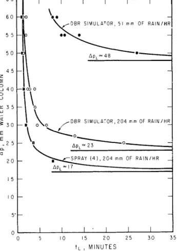
The leakage characteristic of a window was obtained in the following manner. With the window subjected t o a given wetting rate, QFV, and method of wetting, an air-pressure difference ~p was applied across it and maintained until1 leakage occurred a t time tl,; leak- age times were obtained for a number of values of Ap. The relationship between ~p and
tL
represents the leakage characteristic curve of the window for the particular method of wetting and wetting rate. Diffe- rent characteristic curves were obtained by varyingQw or the wetting method. An example of these is shown in Figure 2.
It will be noted t h a t for each curve there is a limi- ting pressure, A P ~ , below which leakage does not occur regardless of the test period. It was found in the present investigation on metal windows without excessive storage capacity, t h a t a test period of 30
minutes was usually sufficient t o determine A P ~ .
This limiting pressure difference can be used t o define the leakage characteristics of such windows.
All the windows were tested with more than one wetting rate, and all but three were tested with one or both of the spray systems. The variations of AP, with wetting method and wetting rate for the test win- dows a r e summarized in Table 11.
The measured leakage characteristics of the two horizontal-sliding windows (2) and (4), the projected window (9), and the pivoted window (10) showed a significant dependence on the wetting rate Qw. Of these, only window (9) was affected by wetting method a s well. The characteristics of windows (5) and (8) were nearly independent of wetting rate and would probably have been independent of wetting method; window (lo),
however, which was affected by wetting rate, might also have been affected by wetting method.
The tests showed t h a t the leakage characteristics a s measured for the range of windows examined did not depend greatly on the rate of water application, or on whether water was applied with spray nozzles or with a n arrangement which attempted t o duplicate the dyna- mic impingement of wind-driven rain.
Table I1
SUMMARY O F WINDOW RAIN-LEAKAGE CHARACTERISTICS Wetting
-I
Method (2) Double horizontal slider, aluminium, plastic track ( 3) Double horizontal slider, aluminium A P ~ , , ~ : mm water I (1) Double horizontal I DBR slider, aluminium DBR Spray (4) Spray (2) Run-on DBR DBR Spray (4) Spray (2) Run-on DBR DBR Spray (4) Spray (2) DBR Run-on (4) Double horizontal DBR slider, aluminium DBR DBR Modified Spray (4) drain holes DBR 51 204 204 204 780 litres/m-hr 51 204 204 204 780 litres/m-hr 51 204 204 204 273 780 litres/m-hr 51 204 273 204I
204 (5) Double horizontal DBR I 51 slider, aluminium I DBR1
204 ( 6) Double horizontal slider, sashless, wood frame, plastic track DBR 51 DBR 204 Spray (4)~
204 (7) Double doublehung, DBR 51 aluminium DBR 204 Spray (4)1
204 Spray (2) 204 DBR 273 (8) Single doublehung, DBRI
51 aluminium, sealed DBR 204 double-glazed DBR I 273 1 (9) Projected (sliding1
DBR I 51 hinge), aluminium, I DBR double-glazed I Spray ( 4) (10) Horizontal-pivoted,I
DBR aluminium, DBR double-glazed DBR - - - - - 204 204 51 204 273 A - - - --The tests also showed t h a t leakage occurred within 15 minutes for all windows except ( 4 ) , (7), ( 9 ) and (10); of these, only window (10) took longer than 30 minutes for leakage to occur.
Conclusion
A standard test method is to be established in North America within the year for determining the water- leakage performance of windows. It is being proposed that a static air-pressure difference be used to simulate the effects of wind and spray nozzles to simulate wind- driven rain.
The investigations reported in this paper have shown that the wetting provided by such a method is not uniform. The leakage performance of a number of windows determined by this method, however, was shown to differ little from t h a t determined with a n apparatus providing more uniform wetting and better simulation of wind-driven raindrops.
Reference
1. Changnon, S. A. and A. J. Jones
Effect of wind-borne rain on weatherproofing. Buil- ding Research, Vol. 1, No. 6, p. 8-11, Nov/Dec 1964.
0 5 10 15 2 0 25 3 0 35
t L
,
M I N U T E SFig. 2. Water-leakage characteristics of window 9.
Resume
Une methode Nord-Americaine d'essai de l'etancheite des fendtres
L'appareil le plus commun6ment employe en Amerique du Nord pour l'essai d18tanch6it6
B
la pluie des fen&- tres consiste en une enceinte o~ rkgne une pression fixe et un pulv6risateurB
buses simulant le moullement de la fenetre par la pluie. Les debits d'eau de mouille- ment et les differences de pressions utilisees au cours des essais varient fortement. Recemment, 1'American Society for Testing and Materials a essay6 d'btablir quel- que uniformit6 parmi ces methodes d'essais. Les auteurs du present expose ont participe ces travaux, a u cours desquels ils ont effectue des mesures de determination des caracteristiques du mouillement realis6 par divers pulv6risateurs B buses sous etude. Des mesures semblab- les ontBte
realisees s u r I'appareillage utilise par les auteurs a la Division des recherches en bstiment du Conseil national de recherches (DBRICNR). Cet appa- reillage est semblable en principe ?celui de 1'Institut inorvegiens des recherches en construction, et donne de l'eau pulverisee a u moyen d'ajutages.
E n outre, des essais ont Bt6 men& s u r un certain nombre de types de fenbtres, en utilisant tant I'appa- reillage de la DBRICNR que les differents genres de pulv6risateurs a buses, en vue de determines les effets des differents debits de mouillement, des differences de pression et du type de mouillement s u r les carac- teristiques des infiltrations.
Ces recherches ont montre que la repartition du mouillement rdalise par les pulv6risateurs 5 buses n'6tait gukre uniforme a la surface des Bchantillons. Cepen- dant les essais realises sur les fenetres ont montre que leurs resistance
a
l'infiltration, telle que determinee Bl'aide des pulverisateurs a buses, differait peu de celle qu'indiq'uait l'appareillage de la DBRICNR, bien que celui-ci fournit un moillement plus uniforme, ressem- blant mieux a celui des gouttes de pluie chassees par la vent.