HAL Id: tel-00608222
https://tel.archives-ouvertes.fr/tel-00608222
Submitted on 12 Jul 2011HAL is a multi-disciplinary open access archive for the deposit and dissemination of sci-entific research documents, whether they are pub-lished or not. The documents may come from teaching and research institutions in France or abroad, or from public or private research centers.
L’archive ouverte pluridisciplinaire HAL, est destinée au dépôt et à la diffusion de documents scientifiques de niveau recherche, publiés ou non, émanant des établissements d’enseignement et de recherche français ou étrangers, des laboratoires publics ou privés.
Conception et modélisation de circuits monolithiques à
diode Schottky sur substrat GaAs aux longueurs d’onde
millimétriques et submillimétriques pour des récepteurs
hétérodynes multi-pixels embarqués sur satellites et
dédiés à l’aéronomie ou la planétologie.
Hui Wang
To cite this version:
Hui Wang. Conception et modélisation de circuits monolithiques à diode Schottky sur substrat GaAs aux longueurs d’onde millimétriques et submillimétriques pour des récepteurs hétérodynes multi-pixels embarqués sur satellites et dédiés à l’aéronomie ou la planétologie.. Engineering Sciences [physics]. Observatoire de Paris, 2009. English. �tel-00608222�
THESE DE DOCTORAT
DE L’UNIVERSITE PIERRE ET MARIE CURIE
Spécialité: Méthodes Instrumentales en Astrophysique et leurs Applications Spatiales (Ecole Doctorale Astronomie et Astrophysique d’île-de-France)
Présentée par
Hui WANG
Pour obtenir le grade de DOCTEUR de l’UNIVERSITÉ PIERRE ET MARIE CURIE
Conception et modélisation de circuits monolithiques à
diode Schottky sur substrat GaAs aux longueurs d’onde
millimétriques et submillimétriques pour des récepteurs
hétérodynes multi-pixels embarqués sur satellites et dédiés à
l’aéronomie ou la planétologie.
Soutenue le 7 Mai 2009 devant le jury composé de:
Mr. Aziz BENLARBI DELAI Président
Mr. Imran MEHDI Rapporteur
Mr. Didier LIPPENS Rapporteur
Mr. Gérard BEAUDIN Directeur de thèse
Mr. Alain MAESTRINI Codirecteur de thèse
Mr. Philippe GOY Examinateur
Mr. Jean-Marc GOUTOULE Examinateur
Summary
This research work proposes a novel approach and topology of a compact two-pixel heterodyne integrated receiver front-end working at room temperature dedicated to planetary and atmospheric sciences. Large arrays of millimeter and submillimeter wave heterodyne Schottky diode-based receivers can offer higher mapping speed and mapping consistency while avoiding the use of cryogenic receivers in planetary and atmospheric sciences.
To reduce the size, the weight and the power consumption of a multi-pixel receiver it is necessary to optimize the interface between the mixers and the local oscillator (LO) unit. Only highly integrated components make building large array heterodyne receivers possible. One solution consists in integrating in the same mechanical block a frequency multiplier and one or several mixers to create a compact sub-array. We studied a configuration featuring one single solid state LO source pumps two 183GHz mixers simultaneously by using an in phase waveguide power divider. The mixers and the frequency multiplier are integrated in a same waveguide block to reduce the extra LO losses. However, the mixer chip and the frequency multiplier were both optimized independently for two stand-alone circuits.
The 183GHz Monolithic Microwave Integrated Circuit (MMIC) subharmonic mixer and the 30/90GHz frequency tripler that integrated in the two-pixel receiver front-end have been fabricated and measured respectively. The mixer circuits have been fabricated with three different European Schottky diode processes. The best measured DSB mixer noise temperature of the single 183GHz subharmonic mixer was 793K at 161GHz. Maximum efficiency of 5% and more than 1mW output power has been measured over the band 80-95GHz for the 30/90GHz tripler. The two-pixel integrated receiver has been optimized with a predicted result of DSB mixer noise temperature of 750K at 183GHz for single pixel.
This is the first published demonstration of a multi-pixel heterodyne receiver working at room temperature with integrated LO source in a same block; this compact topology could be applied for higher frequency and extended linearly for larger array heterodyne receiver.
Résumé
Ce travail de recherche propose une nouvelle approche et la topologie d'un récepteur hétérodyne en ondes millimétrique intégré à deux pixels fonctionnant à la température ambiante, dédié aux sciences planétaire et de l'atmosphère. Des récepteurs hétérodynes multi pixels à diode Schottky aux longueurs d’onde millimétriques et submillimétriques peuvent permettre une cartographie plus rapide et plus cohérente tout en évitant d’utiliser des systèmes cryogéniques.
Pour réduire la taille, le poids et la consommation électrique d'un récepteur à multi pixels, il est nécessaire d’optimiser l'interface entre les mélangeurs et l'oscillateur local. Seulement des microcomposants intégrés permettent de construire des récepteurs hétérodynes à grand nombre de pixels. Une solution consiste à intégrer un multiplicateur de fréquence et un ou plusieurs mélangeurs dans une même structure et créer une sous-unité compacte. Dans notre configuration, une seule source d’oscillateur local pompe deux mélangeurs simultanément en utilisant un diviseur de puissance en guide d'onde. Les mélangeurs et le multiplicateur de fréquence sont intégrés dans une même structure en guide d'ondes afin de réduire les pertes supplémentaires. En outre, le mélangeur et le multiplicateur de fréquence ont tous été optimisés de façon indépendante pour deux circuits indépendants.
Le mélangeur subharmonique monolithique à 183GHz et le tripleur à 30/90GHz intégrés dans le récepteur à deux pixels ont été fabriqués et mesurés. Le chip du mélangeur a été réalisé en utilisant trois différents procédés de fabrication de diodes Schottky européennes et dont la meilleur température de bruit de 793K DSB a été mesurée à 161GHz. Un maximum d’efficacité de 5% et plus de 1mW de puissance couvrant la bande 80-95GHz ont été mesurés pour le tripleur. Le récepteur intégré à deux pixels a été optimisé et une température de bruit du mélangeur de 750K DSB a été prédite par simulation.
Ce sera la première démonstration de récepteur hétérodyne à multi-pixels intégrant la chaine oscillateur local dans une structure, cette topologie compacte peut être appliquée aux plus hautes fréquences et étendue linéairement pour des récepteurs aux plus grand nombre pixels.
Acknowledgements
First and foremost I particularly wish to thank my supervisors, Dr. Alain Maestrini of University Pierre and Marie Curie and Dr. Gérard Beaudin of Laboratoire d’Etude du Rayonnement de la Matière en Astrophysique (LERMA) at the Observatory of Paris. It is their abundant help and invaluable support and personal guidance that made my PhD study smooth. They were always patient to explain the scientific and technical problems I met clearly and simply. Throughout my thesis-writing period, they provided encouragement, helpful advice and proofread hundreds of the thesis drafts. I really enjoy being a member of the group and wishing to continuously work with them in the future.
I would also like to express my gratitude to AB Millimetre in France for supporting part of this Doctoral fellowship, this research work would not have been performed without their support. Many thanks to Dr. Philippe Goy and Mr. Sylvain Caroopen for giving experimental assistances during my PhD period. They also explain and teach me how to use the Microwave Vector Network Analyzer (MVNA).
Thanks also to LERMA and the two directors over my PhD periods, Dr. Jean-Michel Lamarre and Dr. Jean-Michel Pérault, who welcomed and hosted me during the past four years.
I offer my sincerest thanks to Dr. Bertrand Thomas of the Jet Propulsion Laboratory (JPL), who shares knowledge, literatures and experience on the design of Schottky diode mixer, especially at the beginning of my study. He provides me many useful advices and support throughout my study. Without his knowledge, assistance and previous exceptional work on the design of Schottky diode subharmonic mixer, this study would not have been successful. Thanks also to Dr. José Siles of the Department of Signals, Systems and Radiocommunication at the Technical University of Madrid, his useful help and invaluable discussion enhance me on the physics of Schottky diode, which is very important for the improvement of design work. I would particularly like to thank Dr. Juan Prado of the Department of Molecular and Infrared Astrophysics at the Instituto de Estructura dela Materia in Spain, for providing me the calculations of the atmospheric opacity.
Thanks are also due to Dr. David Matheson of Millimetre Wave Technology Group at Rutherford Appleton Laboratory (RAL) in UK, his kindness invitation for me to work during two months in his group. I wish to thank all other members of the group for their enthusiasms made me feel like members of their group, and specially thank to Dr. Byron Alderman for teaching me the basics of micro-assembly operation and his assistance throughout my PhD period.
I am grateful to other members of our group at LERMA who are not only great collaborators but also provide enjoyable atmosphere: Dr. Yan Delorme, Miss. Jeanne Treuttel, Miss. Cécile Jung, Mr. Jean-Michel Krieg, Dr. Maurice Gheudin, Mr. Alexandre Féret, Dr. Rolant Lefevre, Mr. Frédéric Dauplay, Mr. Benoît Lecomte, Dr. Faouzi Boussaha, Dr. Jean-Marie Munier, Ms. Michèle Ba-Trung. With them I shared useful discussions and found an invaluable assistance. Thanks are also due to Mr. Patrice Landry and Ms. Marie-Claude Lemonnier for providing technical documentations. I would also like to thank other members of LERMA, specially, Dr. François Viallefond, Mr. Michel Caillat, Dr. Alain Coulais, and Dr. Frédéric Boone. I enjoyed many conversations we had over lunchtime and thanks for your daily encouragements during last years.
I would also like to thank Ms. Annick Gassais, Ms. Chantal Levivier, Mr. Laurent Girot and Ms. Valérie Audon who made so many and so often-incredible efforts to help me for my administration work.
Finally, I would like to thank my parents for all of their love and support since I was born. Thanks to all of my family and friends who I haven’t mentioned. Without their encouragements and supports, I couldn’t have done it.
This research work was supported by the Doctoral fellowship (Bourses de Doctorat pour Ingénieurs) of Centre National de la Recherche Scientifique (CNRS) and AB Millimetre, the European Space Agency (ESA) contract “Development of Schottky MMICs for High Frequencies” (AO/1-5084/06/NL/GLC), and by the Centre National d’Études Spatiales (CNES) contract “Design and Fabrication of Schottky Diode-Based Monolithic Circuits in the Band 90-380 GHz with UMS-BES Process”.
Table of Contents
Purpose of the work ... 1
Thesis structure ... 2
1 Introduction ... 3
1.1 Millimeter and Submillimeter Heterodyne Receiver ... 3
1.1.1 Millimeter and Submillimeter Wave Techniques ... 6
1.1.1.1 Detectors ... 8
1.1.1.2 Local oscillators ... 10
1.2 Why does one need large array receivers? ... 13
1.2.1 Actual status of the development of large array heterodyne receivers ... 14
1.3 Planar Schottky diode technology ... 17
1.3.1 Structure and principle ... 17
1.3.2 The Schottky Diode Model ... 20
1.3.3 Varistor and Varactor Schottky diodes ... 21
1.3.4 Planar Schottky diode technology ... 22
1.3.5 Applications ... 23
2 Millimeter wavelength monolithic Schottky diode-based circuits... 26
2.1 Modeling tools ... 26
2.2 UMS Planar Schottky diode ... 27
2.3 30/90GHz MMIC Frequency Tripler ... 29
2.3.1 30/90GHz Tripler Design ... 29
2.3.1.1 Tripler topology ... 29
2.3.1.2 Tripler optimization ... 32
2.3.1.3 Complete tripler ... 42
2.3.1.4 Predicted Results ... 44
2.3.2 Measurement of UMS MMIC 30/90GHz Frequency Tripler ... 45
2.3.2.1 Test bench ... 46
2.3.2.2 Measured results... 47
2.3.3 Predicted and Measured results ... 52
2.3.4 Importance of using accurate UMS diode model ... 53
2.3.5 Conclusion and perspective ... 60
2.4 183GHz Integrated Subharmonic Mixer ... 62
2.4.1 General description of a subharmonic mixer ... 62
2.4.2 183GHz mixer design ... 66
2.4.2.2 Anti-parallel pair of diodes optimization ... 69
2.4.2.3 Complete Mixer Design ... 72
2.4.2.4 Predicted results ... 78
2.4.2.5 IF impedance - Z_IF ... 80
2.4.3 RF measurement and results ... 84
2.4.3.1 Mixer fabrication ... 84
2.4.3.2 Mixer measurement ... 86
2.4.4 Comparison of the measured and predicted results ... 89
2.4.5 Perspectives ... 97
2.4.5.1 183GHz mixer using the diodes from University of Bath ... 98
2.4.5.2 183GHz mixer with the diodes from RAL ... 100
2.4.6 Conclusion ... 105
2.5 Two-pixel integrated heterodyne Schottky diode receiver front-end at 183 GHz 106 2.5.1 Concept description ... 106
2.5.2 Design procedure ... 109
2.5.2.1 Preliminary study ... 109
2.5.2.2 Two-pixel demonstrator design ... 113
2.5.3 Proposed two-pixel integrated receiver front-end prototype ... 119
2.5.4 Predicted results ... 122
2.5.4.1 Optimization and predicted results using ADS standard diode model ... 122
2.5.4.2 Optimization and predicted results using adjusted diode model ... 124
3 Conclusions and suggestions for future work ... 126
3.1 Summary and Conclusions ... 127
3.2 Suggestions for Future work ... 127
Appendix A – Mixer test setup at LERMA ... 131
1. Y-factor measurement ... 131
2. IF chain description ... 133
3. Measure of receiver noise temperature using the Y-factor method ... 135
Appendix B - Diode I/V Measurement ... 139
Appendix C – List of Publications ... 145
Abbreviations ... 147
List of References ... 149
List of Tables ... 177
Purpose of the work
The purpose of this thesis is to study and design monolithic Schottky diode-based circuits for large arrays of heterodyne receivers working at millimeter and submillimeter wavelength dedicated to planetary and atmospheric sciences.
In planetary and atmospheric sciences large arrays of millimeter and submillimeter wave heterodyne Schottky diode-based receivers can offer higher mapping speed and mapping consistency while avoiding the use of cryogenic receivers. To reduce the size, the weight and the power consumption of a multi-pixel receiver it is necessary to optimize the interface between the mixers and the local oscillator unit. Only highly integration components make building large array heterodyne receivers possible.
My research has included designing three millimeter wave MMIC Schottky diode-based circuits: a 183GHz MMIC subharmonic mixer, a 30/90GHz MMIC frequency tripler, and a two-pixel integrated heterodyne Schottky diode receiver front-end at 183GHz. Novel techniques intended to improve further the performance of receivers or to provide new ways for receiver circuit implementation have been studied.
One solution consists in integrating in the same mechanical block a frequency multiplier and one or several mixers to create a compact sub-array. A novel approach of designing a multi-pixel heterodyne receiver is demonstrated in this thesis. In our configuration, one single solid state LO source pump two mixers simultaneously by using a waveguide power divider. In addition, the mixers and the frequency multiplier are integrated in a same waveguide block. However, they were both optimized independently for two stand-alone circuits.
All the circuits have been fabricated thanks to a research project financed by ESA (European Space Agency) and CNES (Centre National D’Etudes Spatiales) to study the possibilities of developing Schottky MMICs (Monolithic Microwave Integrated Circuit) for high frequencies based on the European industrial process from UMS (United Monolithic Semiconductors). These developments are dedicated for future airborne and space borne atmospheric limb sounding instruments in planetary and atmospheric applications.
Thesis structure
The work presented in this thesis relates to the study and design of three millimeter-wave circuits using commercial foundry planar Schottky diodes from UMS. During this research work, a fixed-tuned broadband subharmonic mixer working at 183 GHz and a MMIC frequency tripler working at 90 GHz were designed, fabricated and measured respectively. Further study based on these two circuits has been accomplished on the development of a novel two-pixel integrated heterodyne receiver front-end. New topology has been analyzed with predicted results.
Before going deep into the details of the work that was carried out, the contents of this manuscript are summarized here.
Chapter 1 gives a general review of the state-of-the-art millimeter and submillimeter wavelength heterodyne techniques, the development of large array heterodyne receiver and general description of the Schottky diode technology.
In the second chapter, three circuits designed within this thesis are discussed individually, including the knowledge necessary to approach each design, simulation results, measured results and the comparison between simulated and measured results. The 183 GHz MMIC subharmonic mixer chip that designed for UMS diodes has been fabricated with two other different Schottky diode processes from the University of Bath and the RAL, the mixer shares the same circuit layout and mechanical block. Measured results and detailed analyses are discussed.
Chapter 3 gives a summary and overview of this research work. Suggestions for future study include several topologies for developing larger array receiver based on the two-pixel integrated receiver that was proposed and developed in this thesis have been proposed.
1 Introduction
1.1 Millimeter and Submillimeter Heterodyne Receiver
In view of the great significance of millimeter and submillimeter waves for the science community, the techniques and instrumentation used for sensitive millimeter and submillimeter wave astronomical observations and planetary remote sensing have been increasingly developed during the last thirty years.
The millimeter domain is at wavelengths ranging from 10mm to 1mm, covers the range of frequencies from 30 to 300GHz. This band is commonly used in radio astronomy and remote sensing. Then the submillimeter domain is at wavelength ranging from 1mm to 0.1mm, or from 300GHz to 3THz in the frequency domain, which is located between the regions observed by radio telescopes and infrared/optical telescopes.
For astrophysics, the millimeter wave range is especially useful for studying the characteristics of cold molecular clouds in which stars form. And the submillimeter band contains spectral and spatial information on the cosmic background, on very distant newly formed galaxies, and on the early stages of star formation within gas clouds in our own galaxy [Phillips92]. For the past four decades submillimeter wave heterodyne spectroscopy techniques have been widely used for molecular line spectroscopy; the detection, identification and mapping of thermal emission and absorption signatures from lightweight low pressure gases; the study of new star formation; and analysis the composition, and map of distribution, of gas and dust within our own galaxy and the constituents in the cores of distant galaxies [Phillips92, Siegel06a, Siegel07].
The human eye is sensitive only to visible light, which is a tiny fraction of the electromagnetic spectrum; in addition, only a small fraction of the radiation produced by astronomical objects actually reaches the ground, because of atmospheric opacity. Certain atmospheric gases absorb radiation very efficiently at some wavelength, which lead to opacity variation of the atmosphere along the spectrum. For example, water vapor (H2O) and oxygen (O2) absorb radio waves having wavelengths less than about a centimeter, whereas water vapor and carbon dioxide (CO2) are strong absorbers of infrared radiation. Ultraviolet, X-ray, and gamma-ray radiation are
completely blocked by the ozone layer high in Earth's atmosphere (see Figure 1.1). In the millimeter and submillimeter portion of the spectrum, the Earth's atmosphere emits strongly at frequencies corresponding to a number of H2O, O2, O3, and O18O transitions.
Figure 1.1: Atmospheric attenuation properties over a wide frequency range at sea level.
The most significant limitation to the detection of astronomical emission at submillimeter wavelengths with ground-based observatories is atmospheric emission, noise and attenuation. At submillimeter wavelengths, ambient atmospheric water vapor absorbs incoming light. At low altitudes (see Figure 1.2), where most water vapor resides, the atmosphere is very opaque at submillimeter wavelengths; the abundant water vapor absorbs any incoming submillimeter photons before they can reach the telescope. At higher altitudes (see Figure 1.3 & Figure 1.4), however, the water content decreases substantially. Owing to atmospheric absorption issues, ground-based millimeter and submillimeter wave astronomy telescope is limited to high altitude sites such as the site on Mauna Kea, in Chile and the South Pole.
Figure 1.2: The Earth’s atmospheric transmission observed from the ground of Paris with 10 mm of perceptible water vapour above the ground (adapted from [Pardo08]).
Figure 1.3: The Earth’s atmospheric transmission observed from Plateau de Bure (Haute-Alpes, France) with 1 mm of perceptible water vapour above the ground (adapted from [Pardo08]).
Figure 1.4: Earth’s atmospheric transmission observed from Chajnantor (site of ALMA, Chile) with 0.3 mm of perceptible water vapour above the ground (adapted from [Pardo08]).
To overcome these drawbacks, several approaches have been used to get above the atmosphere. One approach has been to use telescope carried to high altitude by balloons [Garnier05]. Another approach has been to use the airborne telescope [Boreiko96] to observe from above most of the atmosphere. While not able to reach altitudes comparable to those of balloons, airborne astronomy and balloon astronomy get above most, but not the entire atmosphere. To avoid the absorption of the Earth’s atmosphere, the only solution is to go into space [Phillips02, Goldsmith07].
1.1.1 Millimeter and Submillimeter Wave Techniques
There are two classes of detectors used in the millimeter and submillimeter region, namely direct and heterodyne instruments. Being situated at the transition region between the heterodyne detection techniques used at radio wavelengths and the direct photo detection techniques used for infrared, optical, ultraviolet, and X-ray astronomy, the submillimeter-wave astronomy benefit the techniques from both regimes.
Direct detections such as bolometers [Richards94], are thermal radiation detectors: an absorber absorbs the incident electromagnetic radiation; its temperature
rises and a resistance thermometer measures the change of temperature. Bolometers have very wide bandwidths and offer better continuum sensitivities; consequently, they are generally useful for continuum detection.
Whereas heterodyne techniques are preferred to direct detection involve the need for high spectral resolution studies in astrophysics and planetary remote sensing [Blaney78, Phillips02, Siegel02, Chattopadhyay04]. Future large telescopes or interferometers in space need very high spatial resolution, which implies relatively small velocity dispersion and therefore high spectral resolution [Phillips02]. In
general, heterodyne detection offers higher spectral resolution (/106) over direct detection [Phillips02, Chattopadhyay05].
Low noise pre-amplifiers are just being available at shorter millimeter wavelength less than 3 mm [Weinreb99, Archer01a, Archer01b, Raja01, Gaier07, Tessmann07] from past few years, MMIC low noise amplifier (LNA) in submillimeter range [Deal07a, Pukala08, Samoska08a] are just becoming to be developed recently. Thus, the typical solution for detecting signals at millimeter and submillimeter wavelengths is to bring the signal down in frequency, without losing information. This is accomplished by a heterodyne receiver in which the signal from the sky called radio frequency (RF) is mixed with a monochromatic signal called local oscillator (LO). The frequency of the LO is very close to the frequency of the signal. In performing such a mixing, the resulting signal is at much lower frequency (at the difference of the two frequencies), while still having all the spectral information of the original signal from the sky (See Figure 1.5).
Figure 1.5: A block diagram of a heterodyne receiver chain (redrawn from [Maestrini99]).
Only heterodyne techniques are briefly described here; more details for submillimeter astronomy techniques could be found in [Phillips87, Charlstrom96, Siegel02, Zmuidzinas07].
Increased progress in millimeter and submillimeter heterodyne receiver technology has been achieved over the last three decades, including the front-end segment, the intermediate frequency (IF) output, the back-end processing [Charlstrom96, Benz05, Klein06] (spectrometer or correlator) and micromachining [Lubecke98, Kirby06, Li08, Bruneau08]. The detectors and LO sources used in heterodyne receiver front-ends are summarized below.
1.1.1.1 Detectors
Heterodyne receivers using cooled HEMT LNA have been employed in radio astronomy since 1980’s [Weinreb88, Pospieszalski93]. As described previously steady improvement has been achieved at millimeter MMIC LNAs especially for high frequency during last few years, furthermore, the highest frequency MMIC LNA has been reported recently up to 360GHz [Samoska08a]. Thus, MMIC LNAs are increasingly being used as receiver front-end in the millimeter wave range particularly for array and imaging applications involving Earth science and planetary [Siegel03]. A Q-band (38-50GHz) MMIC receiver [Kangaslahti06] has been developed for application to detection of the cosmic microwave background (CMB) radiation in astrophysics. At E-band, a multichannel receiver for imaging radar was
reported [Schellenberg07], at W-band, a dual-channel receiver was demonstrated [Tessmann06], and a G-band Multi-chip MMIC T/R module for radar applications was recently reported [Samoska08b]. MMICs are appealing for array receivers.
At millimeter and submillimeter wavelength, three types of mixer technologies are mainly used in heterodyne receivers: Schottky diode mixers, Superconductor insulator superconductor (SIS) mixers and hot electron bolometer (HEB) mixers.
Schottky diode mixers can operate at frequencies up to 5THz [Betz96], which use the nonlinear current voltage characteristic of a metal-semiconductor junction. In the early days of submillimeter astronomy, whisker-contacted GaAs Schottky diode mixers were been commonly used either in a waveguide mount or in an open structure. They have been employed in Submillimeter Wave Astronomical Satellite (SWAS) launched by NASA in 1998 [Melnick00] and Odin launched by teams from Sweden, Canada, France and Finland in 2001[Odin]; they were the two first submillimeter space heterodyne instruments. However, whisker-contacted devices show reliability and handling problems, and space qualification is very difficult. Furthermore, whiskered diodes cannot be integrated. For these reasons, the planar Schottky diode technology has been developed and improved for the last two decades. In the aspect of receiver sensitivities, typical DSB noise temperature of room temperature Schottky diode mixers is about 1800K at 500GHz with approximately 8dB of conversion loss [Chattopadhyay04], improved performance can be achieved when cooled. Last reported subharmonic Schottky diode mixer working at 874GHz [Thomas08a] showed minimum DSB noise temperature of 3000K. The highest Schottky diode mixer has been demonstrated up to 2.5THz [Gaidis00] flown on Aura satellite and 4.744THz flown aboard the Kuiper Airborne Observatory (KAO) [Boreiko96].
In order to develop far more sensitive submillimeter and THz mixers, at least two different superconducting heterodyne detectors have been developed, including the superconducting tunnel junction (SIS) [Dolan79, Richards79, Tucker79] and HEB [Phillips73]. SIS mixers are widely used throughout the millimeter wave bands up to 700GHz, the SIS tunnel junction have already been proven to operate close to the quantum limit (Tnhv /k )[Zmuidzinas04], and extending recently up to frequencies
Stratospheric Observatory For Infrared Astronomy (SOIFA) [SOFIA] and the Heterodyne Instrument for the Far-Infrared (HIFI) on Herschel Space Observatory [Herschel]. However, reverse photon sets a hard upper frequency limit for SIS mixer operation, for all-niobium SIS junctions the limit is around 1.4THz and possible 1.6THz for junctions incorporating higher critical temperature materials [Zmuidzinas04].
At yet higher frequencies, HEB mixers now offer excellent performance at frequencies in the terahertz region that are beyond the reach of SIS mixers, excellent performance has been reported at 2.84THz [Gao07] with a receiver noise temperature of 1050K (below ten times of quantum noise), and at 4.3THz with a DSB receiver noise temperature of 1300K [Khosropanah07].
The SIS and HEB mixers both operate at temperatures well below the superconductor critical temperature (2 to 4K), the requirement of cryogenic lead a significant limitation for remote and long lifetime space operation. One major advantage of Schottky mixers is that they can operate over a very wide temperature range, including room temperature, and can therefore be used in applications in which cryogenic cooling is undesirable or prohibitively expensive. The Schottky diode mixers could be deployed for the Earth observation, planetary science and ground atmospheric research, which do not require sensitivities as high as for astrophysics. However, Schottky diode mixer requires higher local oscillator (LO) pump power, which is at least 1mW, while the required LO power for HEB mixers is in the 1-100nW range, and for SIS mixers is on the order of W [Siegel03].
Consequently, the particular choice is mostly dictated by the available LO power, operating frequency, receiver sensitivity criteria and whether the mixer will operate at room temperature or cryogenic temperatures.
1.1.1.2 Local oscillators
The development of powerful, tunable, monochromatic sources is currently one of the most important issues for the development of high frequency heterodyne instrument particularly in the terahertz frequency range (0.3-10 THz). Solid-state LO chains have rapidly replaced sources using molecular lasers and vacuum tube oscillators such as klystrons, carcinotrons. Direct sources such as carcinotrons or Backward Wave Oscillator (BWO) can operate at frequencies between a few GHz
and 1.2 THz producing substantial output power. However, the disadvantages of these sources lay in their large size, high voltage requirements, low reliability and short lifetimes as well their commercial availability. To overcome the limitations of such direct sources, two successful frequency conversion approaches have been widely used for the power generation at millimeter and submillimeter wavelength: either up to higher frequency from low frequency, or down from the optical or infrared frequencies [Siegel03].
Up conversion from microwave sources is currently the most efficient technique. Gunn oscillators and amplifiers are usually used as the fundamental source with harmonic generation resulting from a nonlinear device such as Schottky diode varactor or heterostructure barrier varactor (HBV) [Kollberg89]. Schottky diode technology is mature and high frequency multipliers have been progressed combing with several related technologies, which include membrane technology, improved micromachining, powerful simulators and increased drive power from MMIC power amplifiers [Maestrini08a]. Frequency multipliers using GaAs Schottky diodes have reported tens of microwatts of output power up to 1.9THz [Maestrini04a] for the Herschel Space Telescope. To increase the power handling of given source, a power-combined frequency tripler at 300GHz has been demonstrated recently in [Maestrini08b], it delivers a peak power of 26mW with 11% conversion efficiency at 318GHz. This approach should be the future trend to improve the power handling of frequency multiplier. Another demonstration of tripler at 900GHz has been reported in [Maestrini08c]; and is expected to be capable of pumping a 2.7THz tripler [Maestrini08b] in near future.
HBVs have a symmetric capacitance-voltage and anti-symmetric current-voltage characteristics; because of these characteristics no even-order harmonics are generated. The odd-order frequency multiplier design is therefore simplified. Furthermore, dc bias is not needed because the capacitance modulation region is centered at zero-bias. HBV multipliers have made significant advances, an output power of 6.5mW and conversion efficiency of 7.2% at 270GHz for a tripler was reported in [Xiao07], an output power of 195mW and conversion efficiency of 15% at 113GHz for a tripler was demonstrated in [Vukusic07], other recent demonstrations could be found in [Melique00, David02, Xiao04, Xiao05, Vukusic06]. However the reported state of the art performances of HBV multipliers
are lower than the power produced by Schottky diode multipliers.
The devices used for up conversion described above need to be driven by a fundamental source at lower frequency. At millimeter wave range, the solid-state power amplifiers (PAs) are frequently used to drive the diode multiplier chain to increase output power and bandwidth for a local oscillator chain [Samoska06]. The commercial W-band PAs [Wang01, RPG] are only available for a few years. Significant progress has been made in increasing the operating frequency of millimeter wave solid-state (PAs) in the past few years, which was pushed by applications including millimeter and submillimeter/THz receivers for astrophysics and earth remote sensing. Increasing the operating frequency of solid-state amplifiers would potentially reduce the number of successive multiplications necessary to reach a particular frequency, and therefore offer significant improvements in total dc efficiency and improve final output power [Deal08, Maestrini08a]. For the novel application in high-resolution submillimeter wave radars [Dengler07], PAs could be used as the fundamental source. Several PAs operating at G-band [Samoska01, Samoska04, Paidi05, Huang06, Deal07b, Deal07c] and even above (>300GHz) have been reported in the last few years; a new submillimeter wave PA topology has been recently reported at 260GHz [Deal08] giving more than 5.9mW output power and is expected to reach the operating frequencies around 340GHz in the near future.
In 2001, a new type of solid-state THz source was developed based on quantum cascade laser (QCL) structures [Köhler02]. Rapid improvement has been achieved over the past few years. QCLs can provide high output power levels, are compact compared to other sources and can achieve frequencies as low as 1.2THz without magnetic field [Williams07]. They have been demonstrated as LO source with superconducting HEB mixers [Gao05, Hübers05]. However, cryogenic cooling is required for continuous wave operation below 2THz. A record operation temperature of 178K has been reported recently for a 3THz QCLs [Belkin08]. Furthermore, their main drawback is the limited frequency tunability [Hindle08].
Photomixers use down conversion from the optical regime for generating millimeter and submillimeter power. The short carrier lifetime, high electrical breakdown field, and high carrier mobility make the Low Temperature Growth (LTG) GaAs suitable for operation well into the THz range. Results have been reported for frequencies up to 3.8THz [Brown95], however poor output power of
about 50W has been achieved at 100GHz and decreased 12dB/octave beyond 500GHz. More recently, a maximum output power of 10.9W at 1.04THz photomixer was reported in [Ito05].
Other commonly used sources at submillimeter wave are FIR-pumped gas lasers [Hodges77], which usually can deliver tens of milliwatts in the terahertz range. However, such lasers are generally massive, bulky and require a lot of DC power, though one 2.5THz gas laser [Mueller98] is currently operating on the NASA AURA Satellite, they are therefore appropriate for ground based applications [Gao07, Maestrini08a].
To conclude, tremendous progress has been made in solid-state LO development at submillimeter wavelengths over last few years, which is being driven by space application such as Herschel.
1.2 Why does one need large array receivers?
With the much-improved performance of state-of-the-art millimeter and submillimeter heterodyne instruments, the dynamic range of ground-based millimeter and submillimeter observations are restricted by the partial transparency and turbulence of the atmosphere that relates to the water vapor content of the atmosphere. To use better the rare appropriate observing conditions and improve the efficiency of ground based or airborne telescope observing time, it is conceivable to perform multiple observations at the same time, requiring arrayed receivers in the focal plane of telescope [Rabanus02].
The array receivers used in millimeter astronomy [Gillespie79] has been discussed for more than two decades, in order to improve the speed mapping of extended molecular line sources. A large amount of observing time at millimeter-wave telescopes with single beam was necessary to observe both the intensity and velocity distribution of the constituents of large molecular clouds [Payne88].
These molecular clouds can be as extended as one to several square degrees in some cases. The parabolic antenna operated at millimeter wavelength has a narrow beam size. It requires a long observation time to map extended sources with a single beam of a small angular size. The observing time required to map a given object may be reduced by adding more beams to the telescope system merely by adding receivers
at the focal plane [Payne88]. Table 1.1 gives minimum observing time in order to map astronomical object with a wide range of sizes with a multi-beam receiver in the range 460-490GHz, and shows that a molecular cloud could be mapped in much less time with array receivers.
Table 1.1 Observing time for the JCMT (i.e. no without calibration) for a 3Jy source at the 3 detection level for different field sizes and number of array elements (Reproduced from [Ardenn87]).
In addition to this fundamental advantage in mapping speed on extended objects, array receivers offer several secondary advantages. With a multi-beam array, a larger region of the sky can be mapped under identical conditions, allowing for better internal consistency, which is especially notable for extragalactic observations. Because the absorbing water vapor changes rapidly with time at submillimeter wavelengths in space and in time, conditions when a map is started may not be at all the same as when the map is finished. Mapping image quality is to be greatly improved due to the homogenous baseline of array receivers. In addition, relative calibration of individual pixels is more accurate since data are taken simultaneously through the same atmospheric path.
1.2.1 Actual status of the development of large array heterodyne receivers
Historically, the basis of focal plane array systems was discussed by [Gillespie79], and an experimental system was developed by [Murphy88]. Then, an array employing SIS mixers working at 345GHz was reported by [Ardenn87]. The first complete millimeter wavelength focal plane array operating on a telescope, which used cooled Schottky diode mixers at 230GHz, was described by [Payne 88].
are cost, size, complexity, availability of local oscillator power and operating temperature of receiver array [Gillespie79]. Fortunately, recent breakthroughs in detector technology, micromachining, local oscillators, amplifier technology, and backend spectrometers now make the construction of large arrays of heterodyne receivers possible [Walker02]. However, there are many challenges and considerations in developing large array heterodyne receiver, such as the array architecture, mixer configuration, local oscillator power coupling, IF layout and backend processing [Chattopadhyay04, Chattopadhyay05a, Chattopadhyay05b].
The choice of mixer technology used in array receiver is dictated by the available LO power, requirement of receiver sensitivity, and the operating temperature of the mixer. Different mixer technologies have been described previously. Available LO power is the major concern for developing the heterodyne array receivers at submillimeter wavelengths [Chattopadhyay04]. HEB mixers require the lowest LO power but tend to have a narrow IF bandwidth. SIS mixers are the most sensitive mixers available today in the 100-1200GHz range and require a reasonable amount of LO power (in order of W). Both HEB and SIS mixers need to be cooled below 4K. On the other hand, Schottky diode mixer can operate at room temperatures and have moderated noise performance, however, they need at least around 1 mW LO power.
Array architecture is critical for the design of the instrument, to improve the LO power distribution and reduce the losses, only high integrated array structure is possible to built large array receiver [Chattopadhyay04]. Various techniques could be employed for multiplexing LO power to a number of mixers simultaneously in a large array receiver, such as beam splitter used in [Groppi00a], direct waveguide coupler employed in [Schuster00], Dammann grating used in [Gusten98] and Fourier grating used in [Graf 03]. With beam splitters, losses show up in absorption and reflection of a few percent due to finite refraction indices, in grating, lost power is scatted away statistically or appears in higher unwanted orders [Rabanus02]. The losses in the LO circuit can be reduced by integrating the last stages of the frequency multiplier chain in the array mixer blocks [Narayanan 02, Chattopadhyay04]. The approach consisting in using individual LO source for each mixer was discussed in [Chattopadhyay04], which means each mixer is pumped with an independent LO source. More recently, a single quartz-based combined Schottky diodes mixer/double working at 380GHz has
been reported in [Thomas08c].
Large multichannel backend became feasible; this leap in spectrometer ability is driven by the rapid expansion in the capabilities of high speed Analog to Digital Converters (ADCs) and Field Programmable Gate Arrays (FPGAs).
Currently, there are only a handful of millimeter and submillimeter wave heterodyne array receivers in operation on ground-based telescope. Table 1.2 summarizes the heterodyne array receivers used in the past, current and under development.
Table 1.2 Past, Current and Future heterodyne array receivers operate in the world.
Receiver Telescope Frequency
(GHz) Beams Technology Year
RETIRED NRAO [Payne88] 12m-NRAO 230 8 Schottky 1987 QUAARY [Erickson92] 14m-FCRAO 86-115 15 Schottky 1990 S115Q 45m-NRO 100-116 4 SIS 1992 NRAO [Payne95] 12m-NRAO 230 8 SIS 1994
SISYFOS 20m-OSO 85-115 16 SIS 1998
CHAMP [Gusten98] 10.4m-CSO 460 15(x2) 1 SIS 1999 OPERATIONAL BEARS [Sunada00] [Yamaguchi00] 45m-NRO 82-116 25 SIS 1998 SEQUOIA [Sequoia] 14m-FCRAO, MA 86-115.6 32 SIS 2000 PoleStar 1.8m- 810 4 SIS 2001
[Groppi00a] AST/RO HERA [Schuster04] IRAM 30m 215-272 9(x2) 1 SIS 2001(May.) SMART [Graf03]
3m-KOSMA 490/810 8x2 SIS 2001(Sep.)
DesertSTAR [Groppi00b] 10m-HHT 345 7 SIS 2005 HARP [Dent00] 15m-JCMT 325-375 16 SIS 2005(Dec.) CHAMP+ [Kasemann06] 12M-APEX 660/810 14 SIS 2006 Under Development SuperCam [Groppi07] 10m-HHT/ 25m-CCAT 330-360 64 SIS since 2004 STAR
[Michael02] SOFIA 1600-1900 16 HEB
Notes
1 Dual polarization
1.3 Planar Schottky diode technology
1.3.1 Structure and principleThe Schottky diode is one of the components most largely used to build mixers and frequency multipliers at millimeter and submillimeter wavelengths. The principle of the Schottky diode resides in the use of a metal contact deposited on a semiconductor substrate of type N. This component has the fundamental advantage to function only with majority carriers that enable it to function at high speed and very high frequency.
Figure 1.6 shows the general structure of an Schottky-barrier diode. The diode is fabricated on a high-conductivity substrate (n-type) that offers high electron mobility, then a very pure high-conductivity buffer layer is gown up on the top of the
substrate to assure low series resistance and to prevent impurities in the substrate from diffusing into the epitaxial layer during processing; the buffer and substrate are doped as heavily as possible, usually on the order of 1018 cm-3 for GaAs. An n epitaxial layer is grown on top of the buffer and doped to 5.1016 to 5.1017 cm-3. The contact of the metal anode to the epitaxial layer forms the Schottky contact. Platinum and titanium are the most common anode materials for GaAs diodes. A gold layer is usually plated onto the metal anode to prevent corrosion and to facilitate a bond wire, ribbon, air bridge, or whisker connection [Maas03].
Figure 1.6: Cross section of a Schottky-barrier diode (reproduced from [Maas03]).
When the metal and the semiconductor are in contact, some of the free electrons in the semiconductor move to the surface of the metal. The semiconductor immediately under the anode that is named the depletion region is depleted of electrons. The uncompensated ions are positive on the semiconductor side and negative on the metal side, this creates an electric field, which opposes further movement of electrons, is set up between the anode and the semiconductor, and a dynamic equilibrium is reached (shown in Figure 1.7 (a)). Because of this electric field, a potential difference, called the diffusion potential or built-in voltage, exists between the neutral semiconductor and the anode.
Depletion width describes the width of the depletion region in the semiconductor, which can be found from the doping density and material parameters of the semiconductor. The depletion width d of an ideal junction having uniform epitaxial doping is:
d 2Vbs
qNd (1-1)
where V is the built-in voltage; b
s is the electric permittivity of the semiconductor;
Nd is the doping density; and q is the electron charge. The depletion width changes when the junction is polarized (DC voltage Vj), which becomes:
d 2(VbVj)s
qNd (1-2)
(a) (b)
(c) (d)
Figure 1.7: Band diagram of Schottky diode when (a) in dynamic equilibrium,
(b)&(c) forward biased, (d) reverse biased.
Fm
Fn
E : Fermi energy of the semiconductor EV : Energy of valence band
qm VLEFm : Work function of the metal
qS VLEC: Electron affinity
qS VLEFn : Work function of the semiconductor
d: depletion region S
m
b q q
q : Barrier metalsemiconductor Vj: Voltage polarization S
m
b q q
qV : Barrier semiconductor metal
VL: Vacuum Level
If the Schottky junction is forward biased (Vj>0), the depletion region
narrows (see Figure 1.7 (b)&(c)) and less charge is stored. The carrier density is large making a large forward current. While the junction is reverse biased (see Figure 1.7 (d)), the depletion region gets wider that increases the drift component of current and decrease the diffusion component. Therefore, the Schottky diode operates as a nonlinear capacitor.
1.3.2 The Schottky Diode Model
Figure 1.8 shows the equivalent circuit of a Schottky diode. Which consist of two nonlinear elements junction resistance Rj and junction capacitance Cj in parallel,
and the parasitic series resistance Rs in series.
Figure 1.8: Equivalent circuit of a Schottky-barrier diode.
The junction capacitance of a Schottky diode depends on the voltage applied to the junction, the relationship is:
Cj(V ) dQ dV Cj 0 (1Vj Vb) (1-3)
where V is the built-in voltage or diffusion potential and b
Cj 0 is the zero voltage junction capacitance, V is the junction voltage shown in Figure 1.8 (Vj >0 if the
junction is forward biased), and
0.5 if the junction is uniformed doped. The zero voltage junction capacitance is:
Cj
0 S qepiNd 2Vb 1/ 2 (1-4)where S is the surface of the anode; q is the electron charge; epi is the electric permittivity of the epilayer;
Nd is the doping density of the epilayer.
The current-voltage characteristic of a Schottky diode can be expressed by the diode equation, which is similar for a pn junction diode (see in Figure 1.7 (c)):
I(V )Is exp qVj kT 1 (1-5)
wherekT / q25.8mVfor T= 293 K (absolute temperature), k is Boltzmann’s constant,
1.371023J /K
, I is the saturation current which is a proportionality s
constant, and is the ideality factor (
1) that accounts for unavoidable imperfection in the junction and for other secondary phenomena that thermionic emission theory cannot predict.
1.3.3 Varistor and Varactor Schottky diodes
The varistor (Figure 1.9 (left)) and varactor diodes (Figure 1.9 (right)) are based respectively on nonlinear resistance characteristic and nonlinear capacitance characteristic of the Schottky-barrier diode.
When the Schottky junction is forward-biased as shown in Figure 1.9 (left), it works as a Varistor diode. The nonlinearity of the resistance allows the Varistor to be used as mixer. The noise mechanism of varistor mixer will be detailed in Chapter 2.4.
When a reverse voltage is applied to the junction, the holes in the p-region are attracted to the anode terminal and electrons in the n-region are attracted to the
depletion region increases as reverse voltage across it increases; and since capacitance varies inversely as dielectric thickness, the junction capacitance will decrease as the voltage across the junction increases. By varying the reverse voltage across the junction, the junction capacitance can be varied. This is shown in the typical varactor voltage-capacitance curve shown in Figure 1.9 (right). Notice the nonlinear increase in capacitance as the reverse voltage is decreased. This nonlinearity allows the varactor to be used as a harmonic generator, like frequency multiplier.
The structure of a Schottky-barrier varactor is qualitatively the same as that of a varistor diode. Since the series resistance consists largely of the undepleted epilayer, the series resistance likewise varies significantly. At high frequencies the importance of minimizing series resistance and maximizing capacitance variation becomes progressively greater. In order to achieve both good efficiency and high output power, varactors require higher breakdown voltages than mixer diodes. The higher the doping level, the less negative the breakdown voltage (lower in absolute value); the larger the epilayer, the more negative the breakdown voltage (higher in absolute value). In lightly doped varactors, electrons may approach saturated drift velocity in the resistive epilayer. This phenomenon increases the incremental resistance in a nonlinear manner.
Figure 1.9: Nonlinear I/V characteristic for varistor diode (left) and nonlinear C/V curve for varactor diode (right).
1.3.4 Planar Schottky diode technology
GaAs Schottky barrier diodes continue being the key element for mixers and frequency multipliers in the millimeter and submillimeter wavelength because no
expensive cryogenic cooling system is required to operate them. In order to overcome the drawbacks of the whisker-contact devices, planar diodes technology has been successfully advanced over the past two decades. GaAs discrete planar diodes flip-chip mounted onto the quartz microstrip circuit have been widely employed with good performances in millimeter and submillimeter mixers [Hesler96, Hesler99, Thomas05] and frequency multipliers [Erickson98]. However, the assembly of the circuit is a challenge as the frequency increases. More recently, integrated Schottky diodes circuits have been successfully developed, either the diodes and the microstrip circuit are both integrated on the GaAs substrate, which is the commonly case, or the integration of the GaAs diode directly on the quartz circuit with a very thin GaAs epilayer.
High quality planar Schottky diodes working at millimeter and submillimeter wavelength have been fabricated for more than a decade at the University of Virginia, now at Virginia Diodes Inc. [VDI], and later at the Jet Propulsion Laboratory [Martin01]. Currently, in Europe, only the Technical University of Darmstadt (TUD) in Germany, and the Rutherford Appleton Laboratory (RAL) in the UK have made significant progress towards fabricating high quality and selling planar Schottky diodes. The process developed in Darmstadt is based on a quasi-vertical structure that mimic whisker-contacted diodes but with an integrated process [Simon93]. RAL Schottky process is very similar to VDI process, with air-bridges formed by wet etching underneath the diodes fingers [Alderman07].
Another industrial Schottky process is available from the French-German company United Monolithic Semiconductors [UMS]. This process does not provide air-bridges for the anodes and has numerous limitations that make its use very difficult at frequencies above 180 GHz [Maestrini04b].
More recently, LERMA and the Laboratiore de Photonique et Nanostructures (LPN) in France have initiated a common research and technology program to develop a Schottky process entirely based on E-beam lithography. Presently, significant progress toward fabricating diodes with nano-dimension and with air-bridges entirely patterned with E-beam lithography has been achieved [Jung08].
1.3.5 Applications
to several THz. In addition, these devices are robust enough to work in hostile environments like in space. All these qualities make Schottky diodes irreplaceable for numerous applications, including Earth’s atmosphere, planetary science, astronomy, radar and security.
Atmospheric scientists are interested in observing the upper atmosphere with remote sensing from either airborne platforms or satellites. Whisker-contact Schottky diodes were used on the Upper Atmosphere Research Satellite (UARS) of NASA to study the Earth’s atmosphere, particularly the protective ozone layer at 205 GHz [Waters93]. At submillimeter wavelength, the Swedish satellite Odin is orbiting the Earth’s atmosphere with four cooled Schottky diode heterodyne radiometers since 2001. Even up to THz frequencies, a low noise Schottky diode mixer at 2.5 THz [Gaidis00] implanted in the Microwave Limb Sounder (MLS) was recently employed on NASA’s Aura satellite to measure microwave thermal emission from the limb of Earth’s upper atmosphere. It was the first space-based heterodyne observations at THz frequency. In the very near future, the Indo-French space experiment Megha-Tropiques will be in operation for understanding tropical meteorological and climatic processes, SAPHIR is a sounding instrument carrying six Schottky diode receivers working near the absorption band of water vapor at 183 GHz. These channels provide relatively narrow weighting functions (see Figure 1.10) from the surface to about 10 km, allowing retrieving water vapor profiles in the cloud free troposphere.
Figure 1.10: Example of weight functions of the 6 channels at Nadir view with a dry atmosphere.
Airborne observation is another approach for the Earth atmosphere science and astronomy. Recently in 2005, Millimetre-Wave Airborne Receivers for Spectroscopic CHaracterisation in Atmospheric Limb Sounding (MARSCHALS) [Moyna06] was successfully flown. MARSCHALS has been designed to be an airborne simulator of a future ESA space instrument MASTER and is the first limb sounder to be explicitly designed and built for the purpose of Upper Troposphere (UT) composition sounding. The principal and most innovative objective of MARSCHALS is to simulate MASTER's (ESA future airborne project) capability for upper troposphere sounding of O3, H2O and CO in the 300, 325 and 345 GHz bands.
For planetary observations, the microwave instrument MIRO [Gulkis06] for the ESA Rosetta Orbiter was launched in 2004, MIRO has two channels at 190 GHz and 560 GHz and employ room temperature planar Schottky diode receivers. Rosetta is devoted to study the comet 67P/Churyumov-Gerasimenko and discover the origins of the solar system and life.
Schottky diodes technology will fly on Herschel and SOFIA, which should be in operation before the end of this decade. They are also candidates for several future planetary missions as TSSM (TITAN), EJSM (Europa Jupiter), and mission for Mars and Earth explorer.
Other applications of Schottky diodes technology include biological and biomedical areas [Siegel04], security and weapons detection, communication, high-resolution radar and imaging, plasma diagnostics by using high high-resolution imaging system. A high resolution imaging radar at 580GHz has been reported recently [Cooper08], this active submillimeter imager employs all-solid-state devices based on Schottky diode sensors and sources and operates at room temperature avoiding cryogenic system.
It is concluded that the planar Schottky diode technology is a strategic technology for millimeter and submillimeter wave instruments dedicated to the study of the Earth’s atmosphere, the study of planets and astrophysics.
2 Millimeter wavelength monolithic Schottky diode-based
circuits
This chapter presents a novel method for designing two-pixel integrated heterodyne receiver front-end. To create a compact sub-array, a frequency multiplier and two mixers were integrated within a same mechanical block, a simple waveguide power divider was used for the LO source contribution. The design of the frequency multiplier and the mixer used in this integrated receiver are described individually, experimental results are discussed.
2.1 Modeling tools
The proper design and optimization methods used in this work have been implanted on two software suites: Ansoft High Frequency Simulation Software (HFSS) [HFSS] and Agilent Advanced Design System (ADS) [ADS].
HFSS is a software package that analyzes the electrodynamics behavior of passive structures by using the finite element method. It computes scattering parameter (S-parameter) response and electromagnetic field distributions for passive and three-dimensional structures at high frequency. The final result is an S-parameter matrix that allows the electromagnetic amplitude and the phase of transmitted and reflected signals to be computed directly from a given set of inputs, reducing the full three-dimensional electromagnetic behavior of a structure to a set of high frequency circuit values.
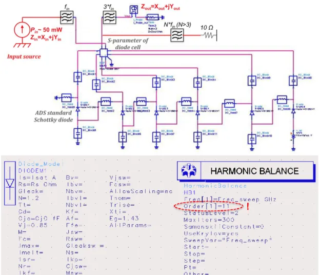
ADS is a powerful electronic design software system. It can offer complete design integration to designers of products such as cellular and portable phones, pagers, wireless networks, and radar and satellite communications systems. The Harmonic Balance simulation method has been used in this work, which is a frequency-domain analysis technique for simulating distortion in nonlinear circuits and systems. Harmonic balance simulation obtains frequency-domain voltages and currents, directly calculating the steady-state spectral content of voltages or currents in the circuit. This method allows one to determine the performance of correspondent circuit.
Figure 2.1 shows the design flow chart for the design and optimization of each circuit by using these two simulators. The three-dimensional structure was first
constructed and the numerical analysis was performed by using HFSS. Thereafter, the physical characteristics of nonlinear element and the numerical results were both implanted in ADS for optimization and determination of the circuit’s performance.
Figure 2.1: Design flow based on two simulators suite.
2.2 UMS Planar Schottky diode
The circuits designed within this work are all based on the UMS MMIC Schottky diode process; Figure 2.2 shows the photo of a single anode Schottky diode from UMS, compared to other typical planar Schottky diode process, no air-bridge to the anode is provided by this process. The epilayer doping and the epilayer length are fixed by UMS BES (Buried Epitaxial Schottky) process.
Figure 2.2: Photo of a single anode Schottky diode with 5 m anode length from UMS.
The physical structure of planar Schottky diodes with different layers is shown in Figure 2.3.
Figure 2.3: Physical structure of Schottky diode of UMS.
As only measurements of diodes (anode gate width) of 4.0 m, 4.5 m and 5.0 m were available when the study started, we used a preliminary study “Report on the Evaluation of the Capabilities of the United Monolithic Semiconductors to Produce Schottky Diodes Based Mixers in the Band 100-380GHz” [Maestrini04b] to estimate the electrical parameters of smaller diodes based on anode dimensions, doping level and edge effects.
a) ideality factor =1.2
b) zero voltage junction capacitances based on the anode dimensions, the doping level and edge effects. [Maestrini04b]:
L (um) Cj0 (fF) 1 1.9 2 3.5 3 5.1 4 6.8 5 8.4 6 10.0 7 11.6
c) Series resistance Rs [Maestrini04b]:
Anode size (um) Series resistance 1.0 11Ω (estimated) 3.0 7 Ω (estimated) 4.0 5.5 Ω (measured) 4.5 4.7 Ω (measured) 5.0 5 Ω typical (specs) Table 2.2 Series resistance dependence versus the length of anode.
2.3 30/90 GHz MMIC Frequency Tripler
Fundamental sources in W-band (75-110GHz) are the key components for various applications including atmospheric remote sensing, radar system and radio astronomy. Many types of multipliers can be used in this frequency region, including active multipliers using transistors and wave-guide varactor diode multipliers. We chose the latter solution in particular. A 6-anode Schottky diode balanced tripler was designed and fabricated. The design of the 90GHz balanced tripler is based on [Maestrini05a]. The tripler uses the so-called open-loop configuration that allows more than two diodes to be easily implanted on chip, increasing the power handling capabilities of the frequency multiplier. This section describes the design method, the simulation results and the experimental results.
2.3.1 30/90GHz Tripler Design
2.3.1.1 Tripler topology
Frequency triplers are complex circuit to design; simultaneous impedance matching has to be achieved in three frequency bands (input frequency, idler frequency and output frequency).
A set of general relations between the real powers at all mixing frequencies in a nonlinear capacitor have been developed by Manley and Rowe [Manley56]. The Manley-Rowe relations are valid for any nonlinear capacitor driven by one or two signals having no commensurate frequencies. They have been applied to parametric amplifiers and up converters as well as to varactor frequency multipliers, and

![Figure 1.2: The Earth’s atmospheric transmission observed from the ground of Paris with 10 mm of perceptible water vapour above the ground (adapted from [Pardo08])](https://thumb-eu.123doks.com/thumbv2/123doknet/14717615.569242/18.892.170.724.105.505/figure-earth-atmospheric-transmission-observed-ground-perceptible-adapted.webp)