HAL Id: hal-01243219
https://hal.inria.fr/hal-01243219
Submitted on 14 Dec 2015
HAL is a multi-disciplinary open access
archive for the deposit and dissemination of
sci-entific research documents, whether they are
pub-lished or not. The documents may come from
teaching and research institutions in France or
abroad, or from public or private research centers.
L’archive ouverte pluridisciplinaire HAL, est
destinée au dépôt et à la diffusion de documents
scientifiques de niveau recherche, publiés ou non,
émanant des établissements d’enseignement et de
recherche français ou étrangers, des laboratoires
publics ou privés.
A Multi-View Co-Modeling and Co-Simulation
Framework for Heterogeneous Embedded Systems
Amani Khecharem, Robert de Simone
To cite this version:
Amani Khecharem, Robert de Simone. A Multi-View Co-Modeling and Co-Simulation Framework
for Heterogeneous Embedded Systems. eSAME 2015 - Embedded software and micro-electronics
conference, eSAME, Nov 2015, Sophia Antipolis, France. �hal-01243219�
Abstract:
Embedded and Cyber-Physical systems pose new demands on modeling and simulation aspects. To the architectural and functional representation of (discrete/cyber) execution platform and running application, one must also associate extra-functional representations for the (possibly continuous) physical environment, as well as power and thermal modeling (for monitoring) of the platform itself. Multi-view modeling, using techniques from Model-Driven Engineering, is a powerful conceptual tool to combine the many aspects of CPS representation. In a first part we shall demonstrate how it can be applied to the case of performance/power/thermal aspects added to an embedded platform model. This work was conducted as part of the ANR HOPE project, also labeled as project from the CIM PACA Design Platform. In a second part, we shall consider how to use emerging standard for co-simulation interface, namely FMU-FMI (first developed in the Modelica community), to bridge the step from co-modeling to co-simulation, and also apply multi-physic co-simulation to the case of various physical view of a same component, while it was until now meant to model distinct component interacting in a larger system, each with its ad-hoc modeling principles. This approach could be used to link in practice several tools found in the CIM PACA Design Platform portfolio.I. INTRODUCTION
Embedded systems are subjected to strong constraints on their non-functional properties, such as heat dissipation, energy consumption, safety and time performance. These properties are modeled and analyzed by experts of specific domains. Each expert has its own dedicated models, domain-specific languages and tools to describe the system model from their point of view. However these models are strongly connected and behavior in one expert model may heavily impact the other expert models. In order to manage the structural and behavioral consistency among various experts models of a single system, architects propose to represent them in views [3]. To this goal, views maintain their consistency by using
correspondences, a syntax and semantic association between
the experts domain models. Model Driven Engineering (MDE) [1] allows experts to define specific domain models. These models are expressed by an explicit language known as Domain-Specific Modeling Language (DSML) [2]. The design of a DSML involves the definition of a meta-model, which contains a syntax and structural semantics.
Our Multi View Approach proposed in this paper is a DSML that expresses the structure and behavior of a system through views. This language provides a framework where experts design their domains, abstracting their concepts to build a specific point of view of the system. We introduce the multi view modeling approach we propose in section II. Then, we detail in section III each of the view domain model as well as the inter-view associations by applying a BIG.Little paradigm example. Finally, we give some conclusions in Section IV.
II. ACO-MODELING AND CO-SIMULATION FRAMEWORK
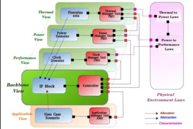
We apply the multi-view modeling to predefine rules and elements that can describe and coordinate different views of a system. More precisely, based on a system backbone, our approach allows defining specific views that are focused on the control of its non-functional properties. Hence, experts from various domains can build a system from their own point of view (time performance, power, temperature, etc.) while maintaining the system consistency by specifying the relationships with the other points of view.
Fig. 1. MULTI-VIEW APPROACH OVERVIEW
To do so, we use MDE to define the syntax of the multi-view system model. MDE is a software design technique where the main artifact is model. A model is built based on a language that gives thenecessary expressivity to represent the elements of a specific domain. This language is described through a
meta-model. A meta-model expresses the concepts and
relationships to build a model by using and conforming to a
eSAME 2015 Conference
A Multi-View Co-Modeling and Co-Simulation
Framework for Heterogeneous Embedded Systems
Amani Khecharem
(1), Robert De Simone
(1)Domain-Specific Modeling Language DSML. DSML proposes to define one dedicated meta-model for each specific domain. In our work, we use the Ecore Modeling Framework (EMF) [4] features to specify our MDE infrastructure. We involve
Ecore representations for our meta-models and Sirius [5]
syntax to create our models.
In the context of power and thermal aware modeling, the system is specialized in five views, as in Fig. 1: a base view called Architecture View, Application View, Performance View, Power View and Thermal view. Each view is split in two Subviews: a StructuralSubView and a BehavioralSubView. The first sub view is composed of subViewElements. It describes, with a component-based approach, the variables and configurations whose value will represent the current state of operation of the controller, seen from other views (e.g. the task graph, the IP Block...). The second sub view controls and schedules the execution of the subView Elements and can also controls other views. The control of the behavioral part will be triggered by explicit events from inside the system, either user-defined or generated from variables measuring physical quantities (e.g. temperatures at the defined location points in the floorplan of the thermal view) Those physical values are themselves correlated according to physical laws, which shall form the last ingredient of our co-modeling framework: thermal view physical values may be related to power value (as a processing resource may consume more power according to its temperature), performance values may be linked to power (as computing faster means consuming more power). We depict these physical law relations on the right of Fig. 1, assuming they may in most case be of continuous nature between real physical units.
To state the relationships between views, we have determined three main types of Correspondences in our architecture description: Allocation, Abstraction and Characterization. Allocation is commonly employed to associate an action from an application to a component in the architecture. Abstraction specifies that the structural element defined in a view is used in another view to specify features that belong to this particular view. Characterization is the association between the behavior of an element from the behavioral part and an equation in the Physical laws part. A change in the element behavior causes the change of the active equation designated by the Characterization correspondence.
III. VIEWS DEFINITION
A. Architecture View
The multi-view approach is based on an architecture view, called also backbone view. This view is the logical representation of the system under development. In the domain of System on Chip (SoC) design, it defines the main view of the Intellectual Property (IP) Blocks diagrams and interconnects. This view presents the reference of objects on which other views shall be “hooked” for their structural
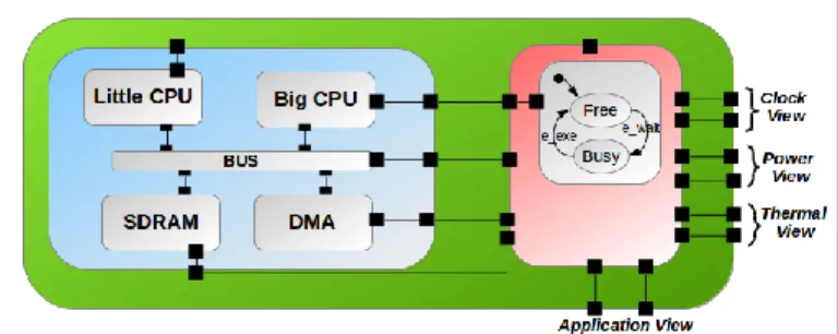
Fig. 2. ARCHITECTURE VIEW OF THE MULTI VIEW MODEL
definitions. Thereby, in this view, the non-functional properties are not defined, they are specified in dedicated views with regards the view under consideration. Fig. 2 presents the Architecture View of our multi-view model. We propose an example SoC [6] which illustrates abstractly the BIG.Little paradigm. The purpose here is to have as simple as possible a description involving blocks with similar functions, but various features concerning performance, power, and to allow temperature differences and alternative mapping. Structural SubView includes five components that are CPU, a little CPU, a Big CPU, a SDRAM and a DMAs connected by a BUS. Behavioral SubView owns the modes of structural components. The modes are defined in state machines (here, we show only Big CPU states). This subView synchronizes also the execution of the Power, Clock and Thermal views according to the Application View execution. We depict in Fig. 2 that Architecture View receives control events from Application View to inform that an action is executed. Therefore, behavioral SubView sends control events to other views to synchronize their execution.
B. Application View
The structural application view represents an abstract task
graph, later candidate to be mapped onto the architecture. The
view also should provide the potential representation (which task and which connection could be mapped on which block for computation or communication). Optionally, the task could also enforce a clock speed on a processor backbone component for execution, and a power configuration as well, requesting the hardware resource it needs for proper execution.
Fig. 3. APPLICATION VIEW OF THE MULTI VIEW MODEL
Fig. 3 presents the Application View of our model.There are two actions. Each action behavior is represented by a state machine, defined in the Behavioral part that contains two states: Execute, when the action is in execution, and Stop, when it finishes or is interrupted. Behavioral SubView commands the execution of the actions. Once an action is
executed, Architcture View is notified to coordinate its components and to notify the other views.
C. Power View
The Power view specifies the elements that intend to supply power and to control power features of system components defined in the Backbone view. To model the structure of the power view, we inspired by the concepts defined in the IEEE-1801 and CPF [7] languages. The power structural subview defines a (discrete) number of power
domains PDs, each encompassing some IP Blocks from the
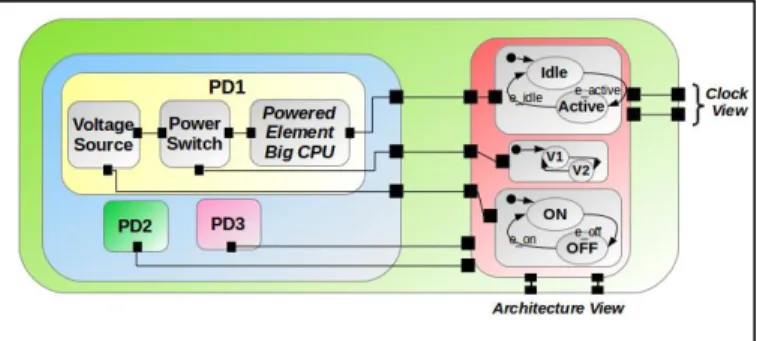
backbone architecture views. PDs can also switch in between a number of admissible power states (off, idle, standby, active...). The behavioral power subview, will describe how to select and switch between these allowable PDs, according to inputs from other views. Fig. 4 presents the Power View of our multi view model. The Structural SubView defines three PDs. They encompass respectively big CPU, LITTLE CPU and (DMA, SDRAM, BUS).Each PD owns a voltage source and power switch to control the current flow. In Fig. 4, we detail only PD1. Each element in the structural part expresses its behavior by a state machine in the behavioral part.
Fig. 4. POWERVIEW OF THE MULTI VIEW MODEL
The powered element Big CPU owns a power behavior whose modes are: Idle, to express that CPU is consuming static power, and Active, to describe that CPU is consuming dynamic power. Voltage Source behavior contains two states: V1 and V2. Each state represents a specific voltage level that is defined in the Physical Law part. The power Switch behavior is expressed by three states that represent the powering on (state ON) and the cutting off (state OFF) of the current from voltage Source to the CPU powered Element. Behavioral SubView receives control events from Architecture View in order to coordinate the power elements behavior.
D. Performance View
The performance view specifies elements that provide and control clock signals. This view is primarily based on clock
domains CD. Each CD encompass a number of blocks from
the backbone architecture view of which they form a partition. In addition, the performance view shall define a (discrete) number of admissible clock speed for every such clock domain. Next to the structural subview, the behavioral subview shall represent an abstract Clock Management Unit CMU, whose purpose is to select and switch between the clock
speeds values (by DVFS according to various inputs from various views). Similarly to PD, we define in the structural subview three CDs which encompass respectively big CPU, LITTLE CPU and (DMA, SDRAM, BUS). In CD, we have the clocked elements abstracted from the architecture view, a clock source and a clock switch. Each of these elements owns a state machine in the Behavioral SubView which receives events from the Architcture View to synchronize its states.
E. Thermal View
The Thermal View describes the domain specified by thermal experts to represent thermal features of the Backbone View elements. Precisely, the structural thermal subview describes an abstract floorplan representations with topology rectangles mapped onto IP blocks from the backbone architecture views. In addition, the structural thermal view should provide the neighboured relation between rectangles, and the laws of temperature diffusion across them (which is continuous, not discrete). In our multi view model, we encompass the big CPU in a thermal domain, similarly for LITTLE CPU and (SRAM, DRAM, BUS). Each thermal domain has thermal elements abstracted from the architecture view. Also, each thermal element has a state machine in the Behavioral subView to control the thermal Behavior. In our case, Big CPU has two states: HIGH, to represent that the CPU temperature rises to its limit, and LOW, to express that the temperature is in a typical operation temperature. Each state is characterized by an equation defined in Physical Part. When the temperature exceed a predefined threshold, Thermal Behavioral SubView sent an event to the behavioral SubView of the Power View to change the behavior of the CPU.
F. Physical Environment Laws
As already mentioned, the physical laws are often of continuous nature, being expressed as ordinary partial differential equations. Modeling environments such as
Modelica or SysML parametric allow this type of
representation (and so does Systemc_AMS in some restricted way). But because there are several such laws being involved, the setting is one of multi-physics co-modeling. Of course, when attempting to simulate or even analyze the behavior of the global system, one is generally required to discretize those laws into difference equations, and the adequate time scaling for discretization steps becomes an enormous issue for applied mathematics and general simulation theory, to maintain realistic and correct dynamics. In practice, in the case of physical relations linking power consumption and time performance, the design of electronic systems-on-chip uses more radical discretization approaches: a finite number of so-called Operating Performance Points (OPP) is defined, which specifies imperatively the legible combinations of clock frequency and power voltage. Those values must of course be in line with physics, but this check is usually supposed to be valid by prior inspection of these definitions. The OPP values allow to enrich the system behavior abilities with the possibility to switch directly from one OPP to another,
on demand from the backbone (firmware) Controller. On the other hand, the laws linking power consumption to temperature do not allow such a discretization scheme, as the law are not linear, and integration through time must be iterated. Here the question is of when should actual events be generated, of discrete nature, to report hotspots back to the backbone Controller ( or report it went back to reasonable), so that proper actions can be taken, such as turning down the clock frequency and the power voltage, or migrating the runnings threads to a different core (or both).
G. Inter-View correspondances
To maintain consistency and to state the relationships between views, we define our model three types of correspondence: Allocation, Abstraction and Characterization. Allocation
Correspondence consists in computing the exact (run-time or
compile-time) mapping between application tasks and backbone architecture resources, under the current configuration in terms of processing resource availability, remaining battery-level energy availability, and current heat at specific chip dye spots. This can be made arbitrarily complex algorithmically, as some effect of a thermal- power aware Operating System. Here certainly more or less sophisticated SystemC operational models could be devised. In our case, and for our current goal aiming more at the preliminary definition of an integrated multi-view co-modeling framework than a realistic co-simulation environment, we shall assume that task mapping is user- provided (as a static, off-line assignment function to backbone architecture resources. Abstraction
Correspondence specifies that a source structural Element is a
representation of a target structural Element between two structural views of different views. We note that big CPU in Fig. 2 is abstracted in the Power view in Fig. 4 to specify the power properties and the power behavior that can be occurred. Characterization is the association between the behavior of a structural element and an equation defined in the Physical laws part. For instance, Idle state shown in Fig. 4 is associate to an Idle, to the static power equation defined in the physical view. Similarly, v1 and v2 are defined.
IV. CONNECTIONS TO ANALYSIS AND SIMULATION TOOLS
The purpose of described framework is to provide an integrated environment in which the various relevant aspects of an embedded platforms are specified, each in its most natural and most abstract fashion, but with common namings and explicit links between the distinct views. The framework can then allow to synthetize simulation or analysis models, by aggregating model components. Simulation models in this area are usually running SystemC code, but this is not mandatory for analysis tools (here we think mainly of tools for model-level optimal allocation of application task graphs onto backbone SoC block diagrams, an approach known as platform-based design, abstracting the operational effect of OS scheduler processing). Inside the ANR HOPE project [8], we collaborate with the LEAT UMR laboratory, which focuses on generating SystemC code for the power and clock manager
policy [11], with Synopsys which provides with its Platform Architect a joint modeling environment for applications and architectures but aims mainly at (power-aware) simulation [ref website], not mapping optimization, and with DoceaPower (whose AcePlorer provides thermal simulation modeling) [9].
V. CONCLUSION
We have described the main features of an environment for co- modeling of the various views relevant to SoC-based design of embedded platforms. The purpose was to define a way by which all these distinct views could be related, without getting into the intricate details of simulation code models. The field of multi-physics co-simulation has recently witnessed renewal of interest, with the FMU/FMI standard interface between plural simulation engines [10], but it addresses only the case where distinct models correspond to distinct components or subsystems. The fact that those models are actually views of the same component object, which therefore have to rely on shared support elements, adds a dimension that we tried to address here in the specific case of SoC hw/sw co-design. ACKNOWLEDGEMENT
This work is partially supported by the ANR INS Projects HOPE (ANR-12-INSE- 0003).
REFERENCES
[1] MDE, «Model driven engineering,» 2007. [En ligne]. Available: http://planetmde.org.
[2] « Proceedings of the 14th Workshop on Domain-Specific Modeling,» Portland, Oregon, USA, 2014. [3] «ISO/IEC/IEEE Systems and software engineering --
Architecture description,» pp. 1-46, 2010.
[4] «Eclipse Modeling Framework,» [En ligne]. Available: http://www.eclipse.org/modeling/emf.
[5] «Sirius,» [En ligne]. Available: http://eclipse.org/sirius. [6] P. Greenhalgh, «Big.little processing with arm
cortex-a15 and cortex-a7,» 2011.
[7] Accelera, «Unified power format 1.0,» [En ligne]. Available: http://www.accellera.org/activities/p1801. [8] «Projet ANR HOPE,» [En ligne]. Available:
http://anr-hope.unice.fr/.
[9] «Aceplorer,» [En ligne]. Available: http://www.doceapower.com/aceplorer.
[10] «FMI [Tools],» [En ligne]. Available: https://www.fmi-standard.org/tools.
[11] H. Affes, M. Auguin, F. Verdier, A. Pégatoquet, «Methodology for inserting Clock-Management strategies in Transaction-Level Models of System-on-Chips,» Forum on specification & Design Languages, 2015.
![[PDF] Cours complet d ADO.NET methodes et pratique | Formation informatique](data:image/gif;base64,R0lGODlhAQABAIAAAP///wAAACH5BAEAAAAALAAAAAABAAEAAAICRAEAOw==)