HAL Id: cea-00930885
https://hal-cea.archives-ouvertes.fr/cea-00930885
Submitted on 24 Sep 2019
HAL is a multi-disciplinary open access
archive for the deposit and dissemination of
sci-entific research documents, whether they are
pub-lished or not. The documents may come from
teaching and research institutions in France or
abroad, or from public or private research centers.
L’archive ouverte pluridisciplinaire HAL, est
destinée au dépôt et à la diffusion de documents
scientifiques de niveau recherche, publiés ou non,
émanant des établissements d’enseignement et de
recherche français ou étrangers, des laboratoires
publics ou privés.
The determination of the structure of Saturn’s F ring by
nearby moonlets
Carl D. Murray, Kevin Beurle, Nicholas J. Cooper, Michael W. Evans, Gareth
Williams, Sébastien Charnoz
To cite this version:
Carl D. Murray, Kevin Beurle, Nicholas J. Cooper, Michael W. Evans, Gareth Williams, et al.. The
determination of the structure of Saturn’s F ring by nearby moonlets. Nature, Nature Publishing
Group, 2008, 453 (7196), pp.739-744. �10.1038/nature06999�. �cea-00930885�
ARTICLES
The determination of the structure of
Saturn’s F ring by nearby moonlets
Carl D. Murray
1, Kevin Beurle
1, Nicholas J. Cooper
1, Michael W. Evans
1, Gareth A. Williams
1& Se
´bastien Charnoz
2Saturn’s narrow F ring exhibits several unusual features that vary on timescales of hours to years. These include transient clumps, a central core surrounded by a multistranded structure and a regular series of longitudinal channels associated with Prometheus, one of the ring’s two ‘shepherding’ satellites. Several smaller moonlets and clumps have been detected in the ring’s immediate vicinity, and a population of embedded objects has been inferred. Here we report direct evidence of moonlets embedded in the ring’s bright core, and show that most of the F ring’s morphology results from the continual gravitational and collisional effects of small satellites, often combined with the perturbing effect of Prometheus. The F-ring region is perhaps the only location in the Solar System where large-scale collisional processes are occurring on an almost daily basis.
Saturn’s F ring, which lies 3,400 km beyond the edge of the main ring system, has presented many unusual aspects and associated dynami-cal phenomena since its discovery by Pioneer 11 (ref. 1). Subsequent imaging by the Voyager spacecraft2,3 showed a narrow ring with multiple components and a twisted, braid-like appearance, contain-ing clumps and radial discontinuities. Voyager radio science4,5and photopolarimeter6 occultation data suggested a core ,1 km wide surrounded by an envelope 50 km wide. Surprisingly, despite the tendency for narrow rings to spread owing to collisions, and the fact that it should be significantly perturbed by its shepherding satellites, Prometheus and Pandora, the F ring is well approximated (residuals ,5 km) by a narrow, uniformly precessing ring of material7.
Early imaging by the Cassini spacecraft8 confirmed the multi-stranded nature of the F ring and displayed streamers and associated channels of ring material gravitationally affected by Prometheus as predicted by numerical models9. Additional observations and mod-elling showed10how the Prometheus streamer–channel cycles and their shearing cause characteristic regular radial and longitudinal variations in the F ring every 14.7-h orbital period. However, the discovery that the apparent multiple strands of the F ring had the structure of a kinematic spiral11was the first evidence that additional objects were involved in producing some of the F ring’s more unusual features.
Two possible explanations were suggested11for the formation of the spiral structures detected in mosaics of the F ring obtained in November 2004, April 2005 and May 2005. The first involved ring material being gravitationally scattered during the close approach of an object with the mass of Prometheus. However, no such object has been observed and Prometheus itself does not enter the ring’s core. The second explanation proposed that particles were pushed out of the ring when a small object passed through it. Additional objects (S/2004 S 3, S/2004 S 4 and S/2004 S 6 with estimated diameters ,5 km) have been detected by Cassini8,12in the vicinity of the F ring, and one of them, S/2004 S 6, was suggested as a possible impactor because of the corres-pondence between its F-ring crossing points and the location of the spirals11. It had been independently suggested13,14that collisions could generate some of the bright clumps in the F ring, but the impactors were thought to be ,10-cm-sized interplanetary meteoroids. The detection of 13 opaque or nearly-opaque objects during stellar occulta-tion experiments using the Cassini Ultraviolet Imaging Spectrograph
and Visual and Infrared Mapping Spectrometer15suggests the exist-ence of objects with diameters ranging from 27 m to 9 km lying within ,10 km of a core that is ,40 km wide; at least one of these objects is opaque enough to be a moonlet rather than a temporary clump of material. The Voyager charged-particle data had already provided evidence16that a 2,000-km-wide moonlet belt surrounded the F ring, and this led to interpretations of the bright clumps as products of the disruptive collisions of loosely bound parent bodies17,18.
All the evidence suggests that the F-ring region is a unique dynami-cal environment in which gravitational perturbations combine with physical collisions to alter the F ring’s appearance dramatically on several timescales. However, the actual mechanisms and objects that change the ring have remained unknown. Here we report on the analysis of a series of images obtained by the Cassini Imaging Science Subsystem19in 2006 and 2007 (see Supplementary Table 1). These show clear evidence for collisional events, the creation and evolution of associated ‘jets’ of material, the gravitational signatures of ,10-km-diameter satellites embedded in the core, the perturbing effects of smaller objects, and direct observations of a narrow (radial width ,1 km) ring component and associated objects.
Colliding objects
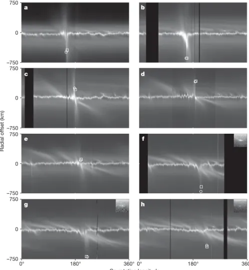
Figure 1 illustrates how the morphology of the F ring changed between 2006 December 23 and 2007 May 5. The mosaics show a region of disturbance in the core that advances from a co-rotating longitude of l 5 150u (Fig. 1a) to one of l 5 226u (Fig. 1h) 133 days later. Furthermore, the disturbance is associated with a sequence of outward or inward extensions of material which we term ‘jets’; these are initially radial but their slope (defined as the angle made with the tangential direction) decreases with time. Note that the individual jets always remain on one side of the core; they therefore represent a distribution in the semi-major axis (a . aF for outward jets and
a , aFfor inward jets, where aF5140,223.7 km is the length of the
semi-major axis of the F ring’s core7), rather than resulting from various eccentricities and longitudes of periapse, as the latter would give rise to jets that oscillated about the core. The observed extent of major jets in the semi-major axis is ,500 km; if this separation were due to gravitational scattering, it would imply a body of diameter ,120 km, which would have been easily detected (see also
Supple-1Astronomy Unit, Queen Mary, University of London, Mile End Road, London E1 4NS, UK.2C. E. de Saclay, Universite
mentary Videos 1 and 2). An alternative and more compelling explanation is that jets (and hence spirals that form from them) are caused by physical collisions11.
Material with a semi-major axis of aF1 Da would be expected to
drift with respect to the core in such a way that after a time Dt its longitudinal drift relative to its initial position would be Dl 5 2(3/2) (n/a)DaDt, where n 5 581.964u per day is the mean motion of material in the core. Therefore, keplerian shear causes the slope of an initially radial jet to be g 5 2(2/3)(a/n)/Dt after a time Dt: it is independent of Da. Consequently, under certain assumptions, the gradient of a jet gives the time at which it was formed. After sufficient time, a radial jet will evolve into a spiral; indeed, the upper halves of the images in Fig. 1a–d display spiral structures exterior to the core, presumably arising from previous events.
It has been suggested11that S/2004 S 6 is a candidate for the object causing the collisional formation of the spiral structures observed by Cassini in mosaics taken in 2004 and 2005. The open circles in Fig. 1
show the predicted locations of S/2004 S 6 based on a new numerical fit to detections from 2004 October to 2005 June (see Supplementary Table 2). Another object, F07090QB, was detected and tracked in the 2007 March, April and May sequences (Fig. 1f–h), and its separately calculated orbital elements bear a striking resemblance to those of S/2004 S 6 (see Supplementary Table 2). The predicted and actual locations of F07090QB appear as open squares in Fig. 1a–e and Fig. 1f–h, respectively. We believe that this object is either S/2004 S 6 or some fragment of it, perhaps perturbed by encounters with material in the core. A more detailed analysis of these orbits will be presented elsewhere. However, the predicted or actual longitude of each object is clearly associated with the progress of the disturbed region, which is consistent with the tabulated differences in mean motion between the disturbing agents and the F-ring core given in Supplementary Table 2. We note that by early 2007 the difference in the longitudes of periapse between the orbits of S/2004 S 6 and the F-ring core was ,159u and is currently increasing at a rate of 1.6u y21;
Co-rotating longitude a b c d e f g h 0° 180° 360°0° 180° 360° 0 750 –750 0 Radial offset (km) 750 –750 0 750 –750 0 750 –750
Figure 1|Sequence of 3606mosaics of the F ring showing evidence for a
series of collisional events between December 2006 and May 2007.In each sequence the mosaic is constructed by re-projecting individual images from Cassini’s narrow-angle camera into a frame in which the horizontal axis is the longitude at the same epoch (12:00UTCon 2007 January 1) and the vertical axis is the orbital radius, r, relative to the adopted orbit of the F ring7. Black
areas indicate lack of longitudinal coverage and all projections are onto the equatorial plane. In each mosaic the circle marks the predicted location of S/2004 S 6 using the orbital elements listed in Supplementary Table 2. The square marks either the predicted (a–e) or actual (f–h) location of the new object using the orbital elements listed in Supplementary Table 2. The inserts in the upper right-hand corners off–hare enhanced, re-oriented 30 3 30-pixel crops of representative raw images showing the objects F07090QB, F07108QA and F07125QB, respectively (see Supplementary Table 2).a, Image
observation ISS_036RF_FMOVIE001_VIMS, consisting of 127 images obtained 2006 December 23–24.b, Image observation
ISS_036RF_FMOVIE002_VIMS, consisting of 130 images obtained 2007 January 5–6.c, Image observation ISS_039RF_FMOVIE002_VIMS, consisting of 124 images obtained 2007 February 10–11.d, Image observation ISS_039RF_FMOVIE001_VIMS, consisting of 143 images obtained 2007 February 27.e, Image observation ISS_041RF_FMOVIE002_VIMS, consisting of 169 images obtained 2007 March 17.f, Image observation ISS_041RF_FMOVIE001_VIMS, consisting of 107 images obtained 2007 March 31.g, Image observation ISS_043RF_FMOVIE001_VIMS, consisting of 94 images obtained 2007 April 18.h, Image observation
ISS_044RF_FMOVIE001_VIMS, consisting of 137 images obtained 2007 May 5. Further information about the observations is given in Supplementary Table 1.
a typical encounter velocity with the core is ,30 m s21, in agreement with the estimated collisional velocity11.
Figure 2 shows a comparison between an enlarged version of Fig. 1g and the results of a numerical simulation of jets evolved from initial radial distributions. The observed features in Fig. 2a that correspond to our modelled jets O1, O2, O3, I1, I2, I3and I6(Fig. 2b) are consistent
with collisions between the F-ring core (or objects orbiting close to it) and S/2004 S 6. However, the smaller jet pairs, O4and I4and O5and
I5, have different characteristics and locations that are inconsistent
with collisions with S/2004 S 6; these jets may be attributed to colli-sions with additional objects. Furthermore, Fig. 2a shows three smal-ler jets with shallow gradients, and an associated bright feature, just above the core at co-rotating longitudes 250u, 295u and 335u; these can also be seen in Fig. 1, moving from right to left. All seem to be associated with objects with semi-major axes ,50 km greater than that of the F ring (see below).
If every close approach between S/2004 S 6 and the core were to lead to a collision, we would expect ,200 jets to be detectable in Fig. 1.
However, Figs 1 and 2a demonstrate that the core is clearly non-uniform in nature; without detailed knowledge of its structure and time variation, as well as the orbits of all nearby objects, the outcome of any given encounter cannot be predicted. After a sufficient time, differential precession causes the gradients of the jets with respect to the core to undergo variations on orbital timescales. However, if the core has sufficient mass, then secular perturbations20may induce the jet material to maintain approximate apse alignment with the core21. Consequently, detailed observations of the formation and evolution of jets may constrain the F ring’s mass. Clearly the orbit of S/2004 S 6 is also subject to the combined secular effects of Prometheus and any mass contained within the F ring22,23(see Supplementary Figs 2 and 3). This may help to explain why the mosaic seen in Fig. 2a closely resembles those seen two years previously (see Supplementary Fig. 1). Embedded objects
The existence of sheared jets of material produced by collisions between objects and the F-ring core has an unexpected consequence: it provides tracer material that allows us to detect the gravitational (or
Co-rotating longitude Radial offset (km) a b O1 I1 I2 I3 I6 I4 I5 I1 I2 I3 I6 I4 I5 O2 O3 O5 O4 O1 O2 O3 O5 O4 600 400 200 –200 –400 –600 0 600 400 200 –200 –400 –600 0 0° 50° 100° 150° 200° 250° 300° 350°
Figure 2|Comparison of a re-projected mosaic with the results of a numerical simulation of jet formation and evolution. a, Re-projected F-ring mosaic derived from observation ISS_043RF_FMOVIE001_VIMS (see Fig. 1g).b, Results of a numerical simulation of jets evolved to the date of the mosaic, 2007 April 18. In each case the data are shown in the standard co-rotating longitude system used in Fig. 1. For the simulation, outward jets of particles were created on 2006 December 18 (O1, co-rotating longitude
l 5 137u), 2007 January 24 (O2, l 5 168u), March 15 (O3, l 5 176u), March
16 (O4, l 5 30u) and March 30 (O5, l 5 230u), and inward jets on 2007
February 6 (I1, l 5 171u), March 7 (I2, l 5 194u), March 22 (I3, l 5 199u),
March 27 (I4, l 5 35u), April 1 (I5, l 5 240u) and April 11 (I6, l 5 210u).
Between 2,000 and 8,000 particles were used to simulate individual events. The particles in each jet were given gaussian distributions in a, e and v relative to the F-ring core model, with standard deviations in Da of either 75 km for large jets or 35 km for smaller jets (half-gaussian distributions with positive values for outward jets and negative for inward jets), in De of 5 3 1025and in Dv of 0.5u. The initial longitude was set to the value at which the jet was created. The particles were allowed to precess under the effects of Saturn’s gravitational harmonics J2, J4and J6and were assumed to orbit at a
mean motion determined by their initial semi-major axes. Their resulting radial locations with respect to the F-ring core and associated co-rotating longitudes are plotted. Note that the formation times and initial longitudes inbwere deliberately chosen to match the features ina; consequently, the timing should be considered as representative rather than exact.
345.57°
Relative radius (km)
Relative radius (km)
Radius – 139,910 (km) Relative radius (km)
165° Co-rotating longitude a b c d e f 80 –80 290 –160 290 –160 290 –160 290 –160 255° 261° 255° 261° 171° 150° 156° 346.57° –0.4° –0.2° 0° 0.2° 0.4° 0 80 –80
Co-rotating longitude Relative longitude
Figure 3|Evidence for embedded satellites on eccentric orbits near the core of the F ring. a, Re-projected 6u section of the F-ring mosaic derived
from image N1538169712, obtained 2006 September 28 at 20:50UTC, showing the existence of a fan associated with the bright clump in the core.
b, The same 6u longitudinal range as ina, but for the image N1538870080, obtained 2006 October 6 at 23:23UTC.c, Fans in a 6u re-projected section of image N1552819237, obtained 2007 March 17 at 10:07UTC.d, Fans in a 6u
re-projected section of image N1557039476, obtained 2007 May 5 at 06:24UTC.
e, 1u re-projected section of image N1537876778, obtained 2006 September 25 at 11:28UTC,showing evidence of a fan.f, Numerical simulation of the gravitational effect of a satellite (radius ,5 km, density 0.4 g cm23,
De 5 1.8 3 1024) embedded at the inner edge of a 50-km-wide F ring
composed of test particles; note that the scale is the same as ine. See also Supplementary Video 3 and Supplementary Fig. 4.
even collisional) signature of embedded satellites. Figure 3a shows an example of a feature consisting of a sequence of sheared channels with a common point of intersection; we refer to this as a ‘fan’. In this case the fan is visible in jet material lying exterior to the F-ring core, in an image taken before the sequences shown in Fig. 1. The channels point to a bright section of the ring with a shallow-sloped, outward, sheared jet going off to the left and a broad jet of material at the upper right. When the same region was viewed 8.1 days later (Fig. 3b), the main structures are still visible but, although there is no fan, dark channels are present in the F ring. Smaller fans are visible in Fig. 3c (a section from Fig. 1e) and Fig. 3d (a section from Fig. 1h), on the same scale as Fig. 3a, b. In Fig. 3d the diagonal features are streamers–channels associated with the previous passage of Prometheus, and the left-hand feature has a fan above it; note the second, smaller fan located between the two streamer–channel features.
Fans are produced by the gravitational effect of an embedded satellite on an orbit that has a non-zero relative eccentricity with respect to the adjacent material. If the relative eccentricity is zero (that is, the satellite has the same orbital eccentricity and periapse as the F ring), then the satellite produces a stationary pattern on the ring material that approaches it. This is identical to the mechanism that is known to generate the propeller features detected in Saturn’s A ring24. If the perturbing satellite has a semi-major axis at the inner edge of a ring of material, only the upper half of a propeller is pro-duced. According to our numerical models, once a relative eccen-tricity is introduced, the satellite’s movement along the ring causes a fan to be produced, with the process continuing as long as material is available to be perturbed. Furthermore, the models demonstrate that the fan goes through a cycle, appearing and disappearing on an orbital timescale, thereby explaining Fig. 3a, b.
Co-rotating longitude 0º –200 –200 200 200 0 0 360º 270º 180º 90º a b c d e f g h i Radial offset (km)
Figure 4|Dynamical structures on a variety of scales in the F ring. a, Comparison of two 360u mosaics of the F ring; the upper and lower mosaics are respectively derived from sequence
ISS_029RI_AZSCNLOPH001_PRIME, obtained 2006 September 25 between 11:18 and 21:07UTC(consisting of 269 non-overlapping images), and sequence ISS_029RF_FMOVIE001_VIMS, obtained 2006 September 28–29 between 20:32 and 10:17UTC(consisting of 93 overlapping images). Each mosaic is constructed from re-projected images covering a 400-km radial range centred on the calculated radius of the F ring’s core and with a co-rotating longitude, l, shifted to a common epoch (12:00UTC, 2007 January 1, as in Fig. 1). We note that the pointing of images in the upper mosaic for l = 100u is only approximate, owing to a lack of stars in the original images. The highest resolution in the upper mosaics is ,1 km per pixel in both the radial and longitudinal directions. The extended radial feature at l 5 26u in the lower mosaic is associated with an object that has also been detected in the upper mosaic.b–d, Enlarged sections of the mosaics inashowing the regions with 138u # l # 158u (b), 220u # l # 232u (c) and
316u # l # 326u (d); all sections are shown on a common scale. The corresponding inertial longitudes covered are 136u , l1,138u,
264u , l2,271u (b); 139u , l1,141u, 263u , l2,270u (c); and
166u , l1,172u, 265u , l2,273u (d), where the subscripts ‘1’ and ‘2’
denote the upper and lower mosaics, respectively.e–g, Enlarged sections of the mosaics inb, showing the respective regions with 138.97u # l # 139.12u (139,950 km # r # 140,050 km), derived from image N1537900950; 152.32u # l # 152.72u (139,940 km # r # 140,040 km), image
N1537899083; and 154.99u # l # 155.19u (139,950 km # r # 140,050 km), image N1537898708.h, Enlarged section of the mosaic inc, showing the region with 230.27u # l # 230.47u (139,950 km # r # 140,030 km), image N1537888059; note the ,1-km-wide linear feature (indicated by the arrows) below the bright component and the 2–3 embedded objects in it (within the circle).i, Enlarged section of the upper mosaic indshowing the region with 324.94u # l # 325.09u (139,950 km # r # 140,050 km), image
N1537878429. We note that the scales ine–iare the same. See Supplementary Figs 5–9 for higher resolution versions ofe–h.
As a representative example of the mechanism, Fig. 3e, f directly compares a fan image to a frame from a numerical simulation of a 50-km-wide ring perturbed by a embedded satellite of ,5 km radius on an eccentric orbit. In our simulations, the maximum longitudinal width of the channels that make up a fan is ,10RH, where RH5
a(m/3)1/3is the radius of the satellite’s Hill sphere, m being the ratio of the satellite’s mass to that of the planet. Given that the widest channel in Fig. 3e is ,100 km wide, this would imply that it is caused by a satellite of radius ,7 km, assuming it has a density comparable to that of Prometheus; this is in good agreement with the value used in the numerical simulation. A similar analysis would suggest that the object responsible for the fan visible in Fig. 3a has a radius of ,35 km; however, the presence of two or three dark bands at this location in Fig. 3b suggests that multiple objects may be responsible. The calcu-lated radii for the objects causing the fans seen in Fig. 3c, d are correspondingly smaller.
Figure 4a shows two mosaics of the region within 200 km of the F-ring core, using re-projected images from 2006 September. The Prometheus channel signature is evident in the lower mosaic for l , 81u across the whole radial region (see also the patterns at l , 75u in Fig. 2a), as are various jets. The sheared channel10patterns are a familiar feature of the F-ring region. However, there are several hundred additional, localized distortions in the F-ring core, examples of which can be seen in Fig. 4b–d. Our numerical models suggest that the effect of keplerian shear would make the channels undetectable within ,100u (or ,20 days) of a Prometheus conjunction, yet Fig. 4a–d shows that the core still retains a ‘memory’ of the last encounter. These localized distortions are time variable; for example, Fig. 4b displays a region of the core covering the same range of co-rotating longitude but in which the inertial longitude differs by ,130u between the two mosaics. We note the two small sections of the ring that point downwards in the upper mosaic and upwards in the lower mosaic. This reflective symmetry is apparent throughout Fig. 4b and, to a lesser extent, in Fig. 4c, d; the phenomenon was first noted in pre-orbit insertion images (see fig. 8c, d of ref. 8) and is indicative of ring material with a small, induced eccentricity and/or periapse relative to the core. There is a tendency for the distortions always to point in the same direction, suggestive of some coherent perturbation similar to the streamer–channel phenomenon produced by Prometheus.
Any given location in the F-ring core has a conjunction with Prometheus every 67.65 days, but the resulting maximum perturba-tion to the core depends on the relative alignment of the two orbits; because of differential precession this follows a ,19-year cycle with the next anti-alignment due in November 2009 (ref. 25). The maxi-mum absolute values of the perturbation in a at alignment, at the orientation when the periapses differ by 90u and at anti-alignment are ,0.5 km, 4 km and 19 km, respectively. The corresponding changes in eccentricity, e, and longitude of periapse, v, are 2, 6 and 13 3 1025, and 0.5u, 1.5u and 4u, respectively. Although the resulting distortions to a ring of test particles shear away, the same would not be true for the orbits of small satellites at the locations of Prometheus conjunc-tions. We conclude that the apparent memory of the core region is caused by Prometheus perturbing masses that lie in or close to the F-ring core, or perhaps core material itself if it is sufficiently massive. Once the orbital elements of these objects are excited, only the self-gravity of the ring and/or collisions can dampen them. Consequently they will, in turn, perturb surrounding ring material or collisional debris, and leave a gravitational signature (see Supplementary Video 4). Figure 4e–i presents selected regions of the high-resolution mosaic on a common scale. Although not always easy to interpret without temporal coverage, each image shows evidence for the existence of small (diameter ,1 km) objects in the F-ring region. Such objects may have associated dust envelopes hindering direct imaging of their surfaces. A common feature of Fig. 4e–g is that the location of each presumed object is correlated with a corresponding feature in the bright core, implying a dynamical connection. The downwards-pointing features in the jet in the upper right-hand region of Fig. 4i
are not seen in the core below, showing that the perturbation is localized; this demonstrates that such perturbed objects can exist at least 50 km from the core. This is the feature seen at l 5 250u in Fig. 2a (see above).
A narrow ring component
In images from the high-resolution observation ISS_029RI_ AZSCNLOPH001_PRIME (upper mosaics in Fig. 4) we have identified a non-continuous, narrow (,1-km-radial-width) ring component located ,15–50 km radially inward from the F-ring core in 45 images with 90u , l , 270u, a range that includes the highest resolution images; in each case the phase angle is ,90u. Eight of these images show evidence of embedded objects (diameter ,1 km) assoc-iated with the narrow component. For example, Fig. 4h contains two or three embedded objects. This and additional images showing the narrow component are shown in Supplementary Figs 9 and 10. A preliminary fit to detections of this component strongly supports the suggestion that it has an orbit that is closely approximated (root-mean-square residuals ,1.34 pixels) by the orbital solution7for the F ring’s core derived from occultation data; in fact, it constitutes a better fit than that based on Cassini observations of the F-ring core. We note that all the re-projected images in Figs 1, 2 and 4 calculate radius with respect to the same orbital model of the core7, and all clearly show deviations of ,50 km. The discovery of such a narrow component would be consistent with the Voyager radio science4,5and photopolarimeter6occultation data but inconsistent with the broad feature present in the data from the Cassini Ultraviolet Imaging Spectrograph and Visual and Infrared Mapping Spectrometer15; it is probable that the latter instruments are detecting the bright F-ring core (width ,50 km) visible in all the Cassini images. Discussion
The existence of a population of moonlets colliding with the F-ring core on a regular basis makes this region unique in the Solar System as a location where the effects of on-going collisions at ,30 m s21 can be studied in situ. Direct observations will serve
to constrain realistic collisional modelling and lead to an improved understanding of the role of such processes in a variety of locations and epochs.
We attribute the ability of the F ring to retain a memory of previous conjunctions with Prometheus to the existence of perturbed, ,1-km-diameter objects associated with the core; larger objects on more eccentric orbits produce the fan structures we have identified in the Cassini images. Therefore, Prometheus plays two roles in perturbing the F ring: its direct perturbations imprint the streamer–channel structures across the whole region as it passes through every 67.65 days10, whereas the same perturbations excite embedded objects that proceed to exert their own gravitational effect on surrounding mate-rial. A probable consequence is that Prometheus itself must be con-tinually struck by material from this region. Future high-resolution imaging of the moon could reveal the effects of recent, direct colli-sions, perhaps in the form of an asymmetry between Prometheus’s leading and trailing hemispheres.
It is difficult to understand how the observed ,1-km-wide ring component seen in some of the highest resolution images can survive in such a chaotic environment. Nonetheless, the evidence suggests not only that it does, but also that it even maintains enough integrity to precess uniformly; the only obvious mechanisms to prevent its destruction are self-gravity and collisions. For this reason, the mass of the F ring perhaps resides in this narrow component rather than the broad, bright, dusty26core seen in every image. This would imply that the narrow component be gravitationally unstable, thereby pro-viding a natural place for moonlet formation. A combination of additional high-resolution imaging and detailed numerical mod-elling (including the effects of collisions and self-gravity) will be necessary if progress is to be made in this area.
A more general question is how were such a ring and its retinue of objects formed. One possibility is that the system is young (,106 years old) and the result of the collisional disruption of a moon by an impact event. This could explain the relatively large dispersion of its constituent objects in contrast to the comparative regularity of Saturn’s main ring system adjacent to it. The F ring’s location also means that its structure could be the result of a continual battle between accretion and disruption17on a variety of scales.
Received 14 February; accepted 7 April 2008.
1. Gehrels, T. et al. Imaging photopolarimeter on Pioneer Saturn. Science207,
434–439 (1980).
2. Smith, B. A. et al. Encounter with Saturn: Voyager 1 imaging science results.
Science212, 163–191 (1981).
3. Smith, B. A. et al. A new look at the Saturn system: The Voyager 2 images. Science
215, 504–537 (1982).
4. Tyler, G. L., Marouf, E. A., Simpson, R. A., Zebker, H. A. & Eshelman, V. R. The
microwave opacity of Saturn’s rings at wavelengths of 3.6 and 13cm from Voyager
1 radio occultations. Icarus54, 160–188 (1983).
5. Marouf, E. A., Tyler, G. L. & Rosen, P. M. Profiling Saturn’s rings by radio
occultation. Icarus68, 120–166 (1986).
6. Lane, A. L. et al. Photopolarimetry from Voyager 2: Preliminary results on Saturn,
Titan and the rings. Science215, 537–543 (1982).
7. Bosh, A. S., Olkin, C. B., French, R. G. & Nicholson, P. D. Saturn’s F ring: Kinematics
and particle sizes from stellar occultation studies. Icarus157, 57–75 (2002).
8. Porco, C. C. et al. Cassini imaging science: Initial results on Saturn’s rings and small
satellites. Science307, 1226–1236 (2005).
9. Giuliatti Winter, S. M., Murray, C. D. & Gordon, M. Perturbations to Saturn’s F ring
strands at their closest approach to Prometheus. Planet. Space Sci.48, 817–827
(2000).
10. Murray, C. D. et al. How Prometheus creates structure in Saturn’s F ring. Nature 437, 1326–1329 (2005).
11. Charnoz, S. et al. Cassini discovers a kinematic spiral ring around Saturn. Science
310, 1300–1304 (2005).
12. Porco, C. C. Satellites and rings of Saturn. IAU Circ.8432 (2004).
13. Showalter, M. R. Detection of centimeter-sized meteoroid impact events in
Saturn’s F ring. Science282, 1099–1102 (1998).
14. Showalter, M. R. Disentangling Saturn’s F ring. I. Clump orbits and lifetimes. Icarus 171, 356–371 (2004).
15. Esposito, L. W., Meinke, B. K., Colwell, J. E., Nicholson, P. D. & Hedman, M. M.
Moonlets and clumps in Saturn’s F ring. Icarus194, 278–289 (2008).
16. Cuzzi, J. N. & Burns, J. A. Charged particle depletion surrounding Saturn’s F ring:
Evidence for a moonlet belt? Icarus74, 284–324 (1988).
17. Barbara, J. M. & Esposito, L. W. Moonlet collisions and the effects of tidally
modified accretion in Saturn’s F ring. Icarus160, 161–171 (2002).
18. Poulet, F., Sicardy, B., Nicholson, P. D., Karkoschka, E. & Caldwell, J. Saturn’s ring-plane crossing of August and November 1995: A model for the new F ring objects.
Icarus144, 135–148 (2000).
19. Porco, C. C. et al. Cassini imaging science: Instrument characteristics and
anticipated scientific investigations at Saturn. Space Sci. Rev.115, 363–497
(2004).
20. Murray, C. D. & Dermott, S. F. Solar System Dynamics Ch. 7 (Cambridge University Press, Cambridge, UK, 1999).
21. Dermott, S. F. & Murray, C. D. Origin of the eccentricity gradient and the apse
alignment of the epsilon ring of Uranus. Icarus43, 338–349 (1980).
22. Murray, C. D. et al. Saturn’s F ring and its retinue. Bull. Am. Astron. Soc.37, 3
(Annual DPS meeting), abstr. 64.05 (2005).
23. Spitale, J. N., Jacobson, R. A., Porco, C. C. & Owen, W. M. The orbits of Saturn’s small satellites derived from combined historic and Cassini imaging observations.
Astron. J.132, 692–710 (2006).
24. Tiscareno, M. S. et al. 100-metre-diameter moonlets in Saturn’s A ring from
observations of ‘propeller’ structures. Nature440, 648–650 (2006).
25. Borderies, N. & Goldreich, P. The variations in eccentricity and apse
precession rate of a narrow ring perturbed by a close satellite. Icarus53, 84–89
(1983).
26. Showalter, M. R., Pollack, J. B., Ockert, M. E., Doyle, L. R. & Dalton, J. B. A
photometric study of Saturn’s F ring. Icarus100, 394–411 (1992).
Supplementary Information is linked to the online version of the paper at www.nature.com/nature.
Acknowledgements C.D.M., K.B., N.J.C., M.W.E. and G.A.W. are grateful to the UK Science and Technology Facilities Council for financial support. The success of the FMOVIE observations described in this paper is due to the invaluable assistance of M. Showalter and the Cassini VIMS team. The authors also wish to thank R. Nelson, D. McNeil, J. Burns and our other colleagues on the Cassini project for numerous discussions.
Author Contributions C.D.M. led the research, worked on image analysis and carried out the jet simulations. K.B. and M.W.E. wrote database and image analysis software, and contributed to image sequence design. Satellite and ring orbit analysis was done by N.J.C., as were the simulations of S/2004 S 6 encountering the F ring. Simulations of planar ring–satellite interactions were done by G.A.W. C.D.M., K.B., N.J.C., M.W.E., G.A.W. and S.C. all contributed to the theories discussed.
Author Information Reprints and permissions information is available at www.nature.com/reprints. Correspondence and requests for materials should be addressed to C.D.M. (c.d.murray@qmul.ac.uk).


![Risiko- & [und] Schutzfaktoren der psychischen Gesundheit humanitärer Einsatzhelfer : eine systematische Literaturübersicht](data:image/gif;base64,R0lGODlhAQABAIAAAP///wAAACH5BAEAAAAALAAAAAABAAEAAAICRAEAOw==)