HAL Id: hal-03011866
https://hal.laas.fr/hal-03011866
Submitted on 18 Nov 2020
HAL is a multi-disciplinary open access
archive for the deposit and dissemination of
sci-entific research documents, whether they are
pub-lished or not. The documents may come from
teaching and research institutions in France or
abroad, or from public or private research centers.
L’archive ouverte pluridisciplinaire HAL, est
destinée au dépôt et à la diffusion de documents
scientifiques de niveau recherche, publiés ou non,
émanant des établissements d’enseignement et de
recherche français ou étrangers, des laboratoires
publics ou privés.
Magnetophoresis Assisted Capillary Assembly of Cobalt
Nanorods: A New Source of Permanent Magnets for
MEMS
Pierre Moritz, Fabrice Mathieu, David Bourrier, Daisuke Saya, Antoine
Gonon, Liviu Nicu, Lise-Marie Lacroix, G. Viau, Thierry Leichle
To cite this version:
Pierre Moritz, Fabrice Mathieu, David Bourrier, Daisuke Saya, Antoine Gonon, et al..
Magnetophore-sis AsMagnetophore-sisted Capillary Assembly of Cobalt Nanorods: A New Source of Permanent Magnets for MEMS.
IEEE 33rd International Conference on Micro Electro Mechanical Systems (MEMS 2020), Jan 2020,
Vancouver, Canada. pp.1175-1178, �10.1109/MEMS46641.2020.9056402�. �hal-03011866�
MAGNETOPHORESIS ASSISTED CAPILLARY ASSEMBLY OF COBALT
NANORODS: A NEW SOURCE OF PERMANENT MAGNETS FOR MEMS
Pierre Moritz
1,2, Fabrice Mathieu
1, David Bourrier
1, Daisuke Saya
1, Antoine Gonon
2, Liviu Nicu
1,
Lise-Marie Lacroix
2, Guillaume Viau
2, and Thierry Leïchlé
11
LAAS-CNRS, Université de Toulouse, CNRS, Toulouse, France
2
Université de Toulouse, LPCNO, UMR 5215 INSA CNRS UPS, 135 av de Rangueil, 31077
Toulouse Cedex 4, France
ABSTRACT
This paper presents the fabrication of high-performance micro-magnets for the electromagnetic transduction of MEMS. The fabrication method relies on the use of nickel microstructures electroplated onto silicon substrates to control the capillary assembly of cobalt nanorods via magnetophoresis under an external magnetic field. The resulting sub-millimeter size permanent magnets with thicknesses of up to 150 µm produce a stray field of 30 mT at a distance of 100 µm. We demonstrate that this magnetic induction is sufficient to actuate a silicon microcantilever by means of the Lorentz force and that the MEMS resonance frequency can adequately be measured using integrated piezoresistances. This novel room-temperature synthesis approach is foreseen to facilitate the integration of high-performance magnets into MEMS.
KEYWORDS
Electromagnetic MEMS, permanent magnet, cobalt nanoparticle, capillary assembly, magnetophoresis.
INTRODUCTION
Electromagnetic MEMS used for sensing [1,2] or energy harvesting [3] call for magnetic sources such as permanent magnets (PMs). High-performance permanent magnets are desirable to enhance the MEMS actuation force or to improve the energy created by MEMS harvesters.
PMs are hard ferromagnetic materials that exhibit a stray field outside the volume without requiring other source of energy. The strength of a PM is represented by its maximal energy product (BH)max, expressing the
energy stored inside the material that can be delivered outside. The (BH)max takes into account the coercive field
Hc, i.e. the capacity of a PM to resist demagnetization, the
squareness of the hysteresis cycle and the remanent induction Br, i.e. the induction obtained without any
external field. In order to generate a stray field far from the source, the volume of the PM has to be large enough to avoid the fast decay of the magnetic induction with increasing distance.
Different techniques are currently used to obtain hard magnetic layers to be used into MEMS. Sputtering provides rare-earth PMs that achieve very high magnetic performances, with (BH)max reaching 400 kJ.m-3, but only
with limited thicknesses (few tens of microns), and thus limited generated stray fields [4,5]. The sputtering technique also requires high-temperature annealing step (> 600 °C) that prevents the facile integration of PMs within the MEMS fabrication process flow. Electroplating
of magnetic materials (e.g. CoNiMnP) is used to obtain thicker films at room temperature, but provides very low magnetic performances (< 15 kJ.m-3) [6]. A last approach consists in diluting isotropic magnetic microbeads inside a polymer [7]. This technique provide thick PMs (100 µm < t < 500 µm) that exhibit moderate magnetic performances (< 30 kJ.m-3) due to the random orientation of the easy axis of the magnetic particles and their low volume fraction.
Therefore, there is a need for methods to fabricate > 100 µm thick PMs with hard magnetic properties (> 50 kJ.m-3) that offer a high degree of integration into a MEMS process flow, i.e. compatible with chemicals routinely used in microelectronics and low temperature.
Previous studies have shown that chemically synthesized highly crystalline Co nanorods (NRs) aligned under an external magnetic field and assembled by capillary forces provide very high (BH)max [8,9]. We have
characterized the stray field generated by such nanostructured materials and highlighted their MEMS actuation performances up to a distance of a few hundreds of micrometers [10]. However, in this previous study, the magnetic material was assembled on a large area without possibilities to pattern the PMs.
Here, we demonstrate that assisting the capillary assembly of Co NRs by magnetophoresis using patterned ferromagnetic structures, Co NRs-based permanent magnets of thickness up to 150 µm can be synthesized at precise locations with controlled shapes and dimensions.
RESULTS AND DISCUSSION
Nanorods
synthesis
and
micro-magnet
fabrication
Cobalt nanorods are synthesized via a polyol process previously reported in [11]. It consists in mixing a precursor of anhydrous cobalt (II) laurate Co(C12H23O2)2
in a basic solution of 1,2 butanediol in the presence of sodium hydroxide and ruthenium chloride and heating the mixture during 20 min at 175 °C. Then, the suspension is cooled down at room temperature leading to crystalline nanorods with a length of 250 nm and a diameter of 15 nm. The excess of organic matter is removed by successive washings in absolute ethanol and chloroform. Finally, Co NRs are dispersed in 300 µL of anisole at a cobalt concentration of 2.8 mol.L-1.
In order to direct the assembly of Co NRs by magnetophoresis, we used 150 µm thick, 500x100 µm2 footprint nickel blocks electroplated on a Si chip through a photoresist mask. We successively deposit 8 times 10 µL of the colloidal suspension (Figure 1 a-b), while applying a 1 T external magnetic field. As can be seen in
figure 1 c-d, the Co NRs are attracted to the Ni blocks. Upon drying, the capillary forces compact the particles, resulting in a dense Co NRs assembly whose thickness and geometry are set by the size and spacing of the Ni blocks (figure 1 e-f).
Figure 1: Successive steps for PM fabrication (schematic views and corresponding photographs, scale bar=500 μm). (a-b) Drop casting of concentrated Co NRs suspension; (c-d) NRs alignment under an external magnetic field and attraction by magnetophoresis; (e-f) dried assembly.
Theoretical considerations
The external field applied during the Co NRs deposition magnetizes the Ni blocks to 480 kA/m saturation magnetization, thus creating local magnetic field gradients in the vicinity of the Ni blocks. These gradients are source of a magnetophoretic force acting on the each Co NR, as expressed by:
(1)
With , the magnetic moment of a NR and , the magnetic induction. Upon application of a magnetic field in the x-direction, the Co NRs align themselves in that direction and the magnetophoretic force becomes:
(2)
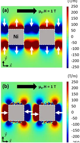
The magnetic field gradient along the x,y,z directions was mapped using Comsol Multiphysics under an applied magnetic field of 1 T to estimate the magnitude of the attractive and repulsive forces around the Ni blocks. The magnetic field gradients along the y-direction is represented in figure 2 a. We observe large attractive zones with gradient magnitudes higher than 250 T/m in between the Ni blocks showing that particles present in these areas are attracted to the center of the blocks interspaces. We also notice a repulsive region, located on the sides of the Ni blocks that induces a particle-free,
depletion zone. The magnetic field gradients along the x-direction are displayed in figure 2 b. The simulations depict large attractive zones between the two Ni blocks that cause the particles to stick to the surface of the Ni blocks.
Figure 2: Magnetic field gradient along the y (a) and x (b) directions around two Ni blocks in an external magnetic field of 1 T applied along x. The white arrows represent the direction of the magnetophoretic forces attracting the Co NRs in between the nickel structures.
Structural and magnetic properties of the created
micromagnets
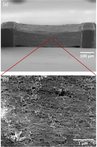
The micro-magnets obtained after drying and capillary assembly consist of two 150 µm thick, 100 µm long and 500 µm wide nickel blocks with a gap of 500 µm entirely filled with a dense assembly of Co NRs (figure 3 a). The SEM image provided in figure 3 b show that the particles display a preferential direction of alignment, corresponding to that of the applied magnetic field. This Co NR alignment provides a strong magnetic anisotropy to the material.
The fabricated PMs were then characterized using a Quantum Design Physical Property Measurement System (PPMS) with the Vibrating Sample Magnetometer (VSM) configuration. Hysteresis measurements were carried out by applying magnetic field ranging from -3 to 3 T. Figure 4 presents the hysteresis cycle of a PM at 300 K. The coercive field reaches a value of 200 kA/m and the remanence induction equals 0.3 T. This value is lower than the performances previously reported [8-10] due to the presence of the Ni blocks that exhibit a very low
coercive field, and to the use of longer Co NRs (250 nm) that tend to intertwine, which decreases the volume fraction of Co at 22 % (compared to 36 % previously obtained). Finally, the maximum energy product is estimated to be 14 kJ/m3.
Figure 3: (a) SEM image of a fabricated permanent magnet consisting of Co NRs assembled in between 100 μm long, 500 μm wide and 150 μm thick electroplated nickel structures. (b) SEM close-up view of the assembly showing a preferential alignment direction.
Figure 4: Hysteresis cycle of a Ni/Co NRs permanent magnet measured at 300 K.
MEMS actuation with Ni/Co NRs magnets
For the MEMS actuation proof of concept, we used a MEMS device consisting of two silicon microcantilevers [2]. A metal line is patterned on each cantilever so as to induce a Lorentz force when injecting a current while the fabricated micromagnet is placed in front of the cantilevers (figure 5 a). One of the cantilevers is free-standing and is actuated by the produced electromagnetic force, while the second one is fixed to the substrate and used as an electrical reference. Implanted piezoresistances are integrated at the clamped-end of each cantilever, where the stress caused by the bending is maximal, in order to measure the MEMS actuation. The mechanical response of the free-standing cantilever was measured by means of a home-built network analyzer.
Figure 5: (a) Optical photograph showing a Ni/Co NRs permanent magnet placed in the vicinity of a silicon
cantilever for electromagnetic actuation. (b) Resonance peaks obtained by placing the magnet at various distances from the MEMS. (c) MEMS amplitude of vibration at resonance and simulated magnetic induction as a function of the magnet to MEMS distance.
For measurement purpose, an alternating current of 30 mA was injected in the actuation electrodes and the piezoresistors were polarized at 1 V. The magnet was placed at a specific distance of the end of the free-standing cantilever and the actuation current frequency was swept so as to measure the MEMS resonance frequency. Figure 5 b shows the resonance plots recorded for different MEMS to magnet distances.
The maximum of cantilever vibration amplitude at resonance is reported in figure 5 c as a function of MEMS-magnet distance. It is important to note that we still clearly observe the MEMS resonance even when the magnet is placed a few hundreds of micrometers away from the cantilever. The magnetic induction generated by the Ni/Co NRs/Ni micro-magnet was simulated with
Comsol Multiphysics (using the hysteresis loops data) and
is reported in figure 5 c. We observe that the experimental measurements and the simulated induction decays in a similar manner with increasing MEMS-magnet distance, highlighting that the MEMS device is only actuated by electromagnetic force. The fitting results indicate that the magnetic induction reaches a value of 30 mT at a distance of 100 µm.
CONCLUSION
In this work, we present the fabrication of Co-based high-performance magnets for MEMS. Our magnet fabrication process relies on a bottom-up approach, where Co NRs are assembled into a dense material by combining capillary forces and magnetophoresis. This method of structuration leads to permanent magnets patterned at precise location, with well-defined geometries and thicknesses up to 150 µm. The assembled magnets exhibit a (BH)max of 14 kJ/m3, providing a stray field of 30 mT at
100 µm and 14 mT at 200 µm. We have experimentally demonstrated that these values are large enough to enable the electromagnetic actuation of a silicon cantilever at distances of a few hundreds of micrometers. Since the method proposed here is a low-temperature process, it should be particularly suited for the direct monolithic integration of thick and high-performance permanent magnets into microelectronics and microsystems processes.
ACKNOWLEDGEMENTS
This work was supported by the University of Toulouse via an APR program (2016) and partly supported by the French RENATECH Network. Authors are grateful to N. Dempsey, S. Cayez, C. Crouzet, F. Chouzenoux and X. Dollat for their help in this study.
REFERENCES
[1] M.-T. Boudjiet et al., “Geometry optimization of uncoated silicon microcantilever-based gas density sensors”, Sens. Actuator B-Chem., vol. 208, p. 600, 2015.
[2] M. Manrique-Juarez et al., “Microelectromechanical systems integrating molecular spin crossover actuators”, Appl. Phys. Lett., vol. 109, no 6, 2016 [3] S. Roy, D. Mallick, and K. Paul, “MEMS-Based
Vibrational Energy Harvesting and Conversion
Employing Micro-/Nano-Magnetics,” IEEE
Transactions on Magnetics, pp. 1–15, 2019
[4] N. M. Dempsey, A. Walther, F. May, D. Givord, K. Khlopkov, and O. Gutfleisch, “High performance hard magnetic NdFeB thick films for integration into micro-electro-mechanical systems”, Applied Physics
Letters, vol. 90, no. 9, p. 092509, 2007.
[5] A. Walther, C. Marcoux, B. Desloges, R. Grechishkin, D. Givord, and N. M. Dempsey, “Micro-patterning of NdFeB and SmCo magnet films for integration into micro-electro-mechanical-systems”, J. Magn. Magn. Mater., vol. 321, no. 6, pp. 590–594, 2009.
[6] M. Han, Z. Li, X. Sun, and H. Zhang, “Analysis of an in-plane electromagnetic energy harvester with integrated magnet array,” Sensors and Actuators A:
Physical, vol. 219, pp. 38–46, 2014.
[7] N. Jackson, F. J. Pedrosa, A. Bollero, A. Mathewson, and O. Z. Olszewski, “Integration of Thick-Film Permanent Magnets for MEMS Applications”,
Journal of Microelectromechanical Systems, vol. 25,
no. 4, pp. 716–724, 2016.
[8] E. Anagnostopoulou, B. Grindi, L.-M. Lacroix, F. Ott, I. Panagiotopoulos, and G. Viau, “Dense arrays of cobalt nanorods as rare-earth free permanent magnets,” Nanoscale, vol. 8, no. 7, pp. 4020–4029, 2016.
[9] K. Gandha, K. Elkins, N. Poudyal, X. Liu, J. P. Liu, High energy product developed from cobalt nanowires, Sci. Rep. vol. 4, 5345 (2014).
[10] P. Moritz, F. Mathieu, D. Bourrier, D. Saya, T. Blon, K. Hasselbach, R. Kramer, L Nicu, L.-M. Lacroix, G. Viau, and T. Leïchlé, Tech. Digest Transducers, pp. 1748-1751, 2019.
[11] M. Pousthomis, E. Anagnostopoulou, I. Panagiotopoulos, R. Boubekri, W. Fang, F. Ott, K. Aït Atmane, J.-Y. Piquemal, L.-M. Lacroix, G. Viau,
Nano Research vol. 8 n°7 pp. 2231-2241, 2015.