HAL Id: hal-00830069
https://hal.inria.fr/hal-00830069
Submitted on 4 Jun 2013
HAL is a multi-disciplinary open access
archive for the deposit and dissemination of
sci-entific research documents, whether they are
pub-lished or not. The documents may come from
teaching and research institutions in France or
abroad, or from public or private research centers.
L’archive ouverte pluridisciplinaire HAL, est
destinée au dépôt et à la diffusion de documents
scientifiques de niveau recherche, publiés ou non,
émanant des établissements d’enseignement et de
recherche français ou étrangers, des laboratoires
publics ou privés.
Realistic and Efficient Rendering
Frédéric Boudon, Alexandre Meyer, Christophe Godin
To cite this version:
Frédéric Boudon, Alexandre Meyer, Christophe Godin. Survey on Computer Representations of Trees
for Realistic and Efficient Rendering. [Research Report] 2301, LIRIS UMR CNRS 5205. 2006.
�hal-00830069�
A Survey of Computer Representations of Trees for
Realistic and Efficient Rendering
Fr´ed´eric Boudon
Alexandre Meyer
Christophe Godin
Abstract— This paper gives an overview of computer graphics
representations of trees commonly used for the rendering of complex scene of vegetation. Looking for the right compromise between realism and efficiency has lead researchers to consider various types of geometrical plant models with different types of complexity. To achieve realist plant model, a complex structure of plant with full details is generally considered. In contrast, to promote efficiency, other approaches summarize plant geometry with few primitives allowing rapid rendering. Finally, to find a good compromise, structures with adaptive complexity are defined. Theses different types of representations and the ways to use them are presented, classified and discussed.
The proposed classification principles rely on the type of struc-tural details used in the plants representations. Characterization of all these methods is completed with various additional criteria including rendering primitive type, distance validity, interactive possibilities, animation ability and lighting properties.
Index Terms— I.3.6 [Computer Graphics]: Methodology and
Techniques – Graphics data structures and data types. I.6.9 [Sim-ulation, Modeling, and Visualization]: Visualization – Visualiza-tion techniques and methodologies. Trees, Real–time, Geometrical modeling, Multiscale Representation, Image-based rendering, Point-based rendering, Shaders.
I. INTRODUCTION
Reproducing natural scenes as realistic as possible has always been a major goal of computer graphics. Over the last decades, computers and techniques have evolved to a point where highly complex scenes can be routinely created. Many urban visualization applications and games already achieve high level of realism. However, vegetation, which is an important part of natural scenes, is not always convincing. Plants, and especially trees, are extremely complex ob-jects, generally composed of numerous organs with particular arrangements in 3D space. Rendering realism therefore de-pends on particular characteristics of vegetal scenes:
• Complexity of organ shapes. At the human scale of
perception, organs like flowers, leaves, fruits, trunks and branches often have complex shapes with varying degrees of symmetry, and lots of significant details.
• Variety of organ shapes. A complex natural scene may
contain dozens to hundreds of plant species, showing an important variety of organ shapes.
• Number of organs. Plants and plant communities
com-monly contain a huge number of organs or individuals. [email protected], ISA Team, INRIA Lorraine, Nancy, France. [email protected], LIRIS Lab, Lyon, France. This paper was begun at GRAVIR Lab.
[email protected], UMR AMAP, Virtual Plants Team, INRIA-CIRAD-INRA, Montpellier, France.
• Spatial organization of organs. The spatial distribution
of plant organs obviously respects particular rules that depend on each species: branches are connected to each other, leaves are arranged along axes following various types of phyllotactic patterns and inclination angles, branches bend in particular ways and directions, etc.
• Plant aspect drastically varies with observation distance.
At close distances, a plant usually exhibits a branching system with detailed organs. At higher distances, the same plant gets homogenized due to the aggregation of many individual details: the complexity of its branching system is less visible and may completely disappear, individual leaves in the crown cannot be distinguished from one another, and the overall impression of the crown is that of a fuzzy volume with a rather regular surface boundary.
The difficulty of modeling and rendering plants reflects this natural complexity. As a consequence, computer representa-tions of plants need to be adapted to particular rendering situations. For close views, fine-grain details are required, while for distant views simple models are preferred to avoid excessive computation and aggregation artefacts. However, in many situations (during zooming operations or during a walk-through in a natural scene), intermediate models whose complexity can be adapted to their visual importance are required. These different types of models can coexist in the same application but requires different construction and vizualization techniques. However, most classical rendering optimization and simplification techniques that successfully apply on regular objects (see [LRC+02] for a review), visually
produce non-adequate results for plants due to their disparate aspect. To face this problem, researchers have developed in the last decade a wide range of techniques and strategies to efficiently model and simplify the rendering of plants.
The goal of this paper is to survey the numerous computer representations of plants and the associated modeling and rendering strategies used to represent vegetation in computer graphics. In a previous work, Mantler et al. emphasized techniques used for 3D real time rendering and proposed a classification of the approaches based on rendering primitives [MTF03]. In this work, we introduce an alternative classifica-tion based on plant representaclassifica-tion structures, and on secondary additional criteria which enables us to review a wide spectrum of rendering approaches. Note that we do consider geometrical modeling of plant organs but we do not address the problem of how plant branching structures are generated which is an important related topic (for detailed reviews see [PHHM97],
[DL05]), but which would extend too much the scope of this review. Similarly, we do not address techniques of occlusion culling, which can be used to accelerate the visualization of natural scenes (a survey of this topic can be found in [COCSD02]).
To organize the various reviewed approaches, we first classify the different types of plant representations according to their level of complexity (Section II). This classification principle is then used as a guiding canvas for the survey. The different techniques used to represent plant modules and branching systems in a detailed approach are depicted in Section III, with a special focus on plant organ design. Subse-quently, global strategies to render efficiently plant models are discussed in Section IV. Eventually, intermediate (multiscale) approaches that make an attempt to combine the advantage of both detailed and global approaches are revieewed in the two last sections : structural-based approaches in Section V and spatial-based approaches Section VI.
II. CLASSIFICATION
A. The structural criteria of plant representations
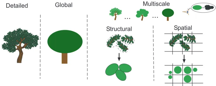
Our classification is first related to the level of details of the plant representation. Such taxonomy was already considered by Godin [God00] for discussing functional-structural models of plants. Three main axes can thus be defined (see Figure 1):
• Detailed representations.
To achieve realistic representations, plants are decom-posed into simples modules (leaves, internodes, etc.) and a geometrical model is built from their union. Such approaches aim at defining continuous geometry of branching systems and realistic geometry of leaves and barks with efficient and intuitive techniques. The possibility of representing a large amount of details make them particularly adapted for close views.
• Global representations.
By contrast, at the lowest level of complexity, plants are considered as a whole. Some works attempt to represent trees with a single or few primitives to drastically simplify vegetal scene rendering. Those representations are usually adapted for distant views.
• Multi-scale representations.
Intermediate approaches handle the whole range of viewpoint distances using representations with adap-tive complexities (levels of details LOD). Thus, the third part of our classification is dedicated to tech-niques which define several scales of representations. Such multi-scale approaches can be divided into two. A first category make use of the hierarchical structures and the repetition of similar objects in the structure to setup simplification scheme, using instantiation or organs clustering for example. A second category refers to approaches that consider multi-scale organizations based on the spatial prox-imity of the elements. Since the tree structure is not needed, these second category of approaches has the advantage of being relatively independent of the modeling process.
In addition to these structural axes, we identified several criteria that should be taken into account when reviewing vegetation representations for rendering.
B. Rendering primitive criteria
The rendering primitive has direct impact on the result, in term of realism and computational time. In the techniques pre-sented in this paper, we distinguish four rendering primitives:
• Polygon.
Computer graphics representations are commonly based on Polygon. Nevertheless, due to the huge number of resulting primitives, the rendering of forest scene is very costly and very subject to aliasing.
• Image-based.
With the cost of a single primitive, an image can rep-resent a very complex object. Image-based rendering (IBR) has become a major technique for rendering real-world scenes acquired as images, or models with very high polygon counts. A large number of image-based rendering methods addressing different kind of problems have been proposed in the last few years [ZC04]. Despite the low cost of an image, IBR introduce many limitations around diversity, lighting, and animation because of the static nature and the relatively high memory cost of an image.
• Volumetric approach and shader-based.
Trees belong to this category of objects that have no defined surfaces, since details merge with distance. An idea is to replace the indistinguishable data by a fuzzy primitive that would reproduce the same photometric behavior (reflectance model or shader) than the group of geometry it represents. The two main advantages of shader in comparison to an ex-plicit representation of details with geometry are the gain in term of computation time and the low level of aliasing. Nevertheless, shaders can be difficult to parameterize or derive.
• Point-based.
A majority of objects in naturals scenes paradoxically covers only fractions of pixels. The traditional ad-vantage of polygon-based scan-line coherence is thus lost, while resources are wasted. An interesting recent alternative is to use point-based rendering [LW85], [PZvBG00], [RL00], [MZG01]. The idea of drawing many simples points having roughly the size of a pixel can be conveniently apply to render vegetation. The number of drawn primitives can be adapted to the distance to ensure interactive frame rate. However, to build a coarse level, points are averaged and are generally made opaque to avoid sorting and blending. This makes anti-aliasing difficult and change the visual appearance to a more opaque object.
C. Additional classification criteria
• Off-line or realtime rendering. Is the presented
Multiscale
Global
Detailed
...
...
Structural
Spatial
=Fig. 1. Classification based on structural complexity: First, detailed representations are considered; then global representations which represent efficiently plants with few primitives and finally multiscale models with adaptive complexity. Multiscale models are divided into two classes: Models that are build using the plant modules hierarchy and models build using generic space organization rules.
the use of off-line rendering allow to improve realism ?
• Distance validity of the technique. What is the
distance range at which the method provide accurate results?
• Animation. Does the method allow animation of
branches, leaves? This question is mainly addressed to realtime methods.
• Lighting characteristics. Several points characterize
a lighting:
• Does the lighting take into account the
self-shadowing (branches and leaves of the tree shadow other parts of the same tree) ?
• In a forest, a tree is also shadowed externally by neighboring trees. Does the lighting compute shadows cast by other trees? Which shadow technique is used?
• Can the lighting be dynamic (for realtime ren-dering)? If yes, what are the limitations?
• Need of pre-computation. Does the method build the
representation as a pre-process? Or does the method generated the representation on the fly? This point induced an impact on many other aspects like the diversity allowed, the capacity of having a dynamic lighting and animating.
• How does the method build the representation?
Does it use a specific modeling process adapted to a particular application? Or does it convert a standard modeling method’s output? Or does the method sim-ply start from a classical polygonal representation?
• Vegetation specific or more general. Few presented
techniques are not specific to vegetation. Neverthe-less, we include them in this survey because they were mainly illustrated on vegetation.
III. DETAILED REPRESENTATIONS
Detailed representations aim at figuring the geometry of tree in the most realistic manner for close views. Trees are generally divided into trunk, branches and leaves which require different modeling and rendering techniques. Branches are generally built with a set of connected geometrical primitives on which textures representing barks can be applied. In this section, modeling techniques used to build the geometry of branches are first presented (Section III-A). Then, we discuss how more realistic rendering of branching systems can be achieved by using bark textures on branches (Section III-B) and detailed representations of leaves (Section III-C).
A. Branching systems
In the design of realistic trunk and branches representations, the challenge is to create continuous models from a discrete set of geometrical primitives. The main difficulty is thus to define an accurate representation of the branch junctions. Various solutions have been proposed in the literature.
1) Pioneering approaches: The simplest step in the quest
for realism of branching structures is the representation of branch segments as 3D cylinders. To minimize memory cost, De Reffye et al. [dREF+88] use a library of symbols (such
as polygonal cylinders) that are reused in different positions, with various dimensions and orientations, and which represent different instances of the same module (internode, growth unit, segment, etc.). Position and orientation of two successive mod-ules can be defined relatively using turtle geometry [PL90]: to draw new organ, commands are passed to a LOGO-style turtle that process them in the continuity of the previous drawn organs. Kawaguchi [Kaw82] propose circular polyhedron to represent continuously the geometry of the slices of branching pattern (see Figure 2).
Unfortunately, these techniques do not properly capture the geometry of branch junctions, since some gaps or
discon-tinuities between elements may appear. Several subsequent solutions have been proposed to address this problem.
Fig. 2. Left: Branching point geometry with circular polyhedron according to Kawaguchi [Kaw82]. Right: Example of branching structure.
2) Cone–Sphere: Max [Max90] introduced the cone–sphere
primitive to model branches. A cone–sphere consists of two spheres with a cone tangent to the two spheres and lying between them (see Figure 3). The outer surface of an elbow is formed by a piece of sphere resulting in a smooth junction of surfaces. But at the inner side of the elbow, the two cones intersect directly, leading to discontinuity of the tangents. A blending method is introduced to improve this based on a simple linear interpolation scheme. While cone–spheres suffice as an efficient representation of individual limbs, they offer no help in the blending and texturing at branching points. Differ-ent extensions of this approach with implicit formulation have been subsequently proposed [HB96], [Mar03], [GMW04a].
Fig. 3. Cone-Spheres used to model branches.
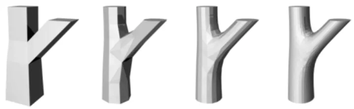
3) Generalized cylinders: To improve realism of branches
and branching points, Bloomenthal [Blo85] introduced gener-alized cylinders. His approach starts from a skeleton with a position associated with each nodes. To obtain continuity of the first and second derivatives at each node, the skeleton is built from the cubic spline interpolation of each set of n edges (n+ 1 nodes) forming a branch.
The geometry of each branch is then built with a generalized cylinder, obtained by sweeping a planar generating curve, de-termining the branch’s cross section, along the skeletal spline curve. The specific difficulty of modeling realistic branching points is handled by connecting several generalized cylinders using several parametric surfaces forming a ”saddle” as shown in Figure 4.
To build the mesh of the generalized cylinder surface, a certain number of sections are evaluated along the skeleton and are connected. Even if not considered in this work, this parametric model additionally allows different degrees
Fig. 4. Representation of the branching points with a ”saddle” surface, built by crafting several parametric surfaces. On the right, texture parametrization [Blo85].
of polygonization and thus offers a basic multi-resolution scheme. Figure 5 illustrates the visual quality of the result.
Fig. 5. The mighty maple [Blo85].
4) Implicit surfaces: Bloomenthal also introduced implicit
surfaces [Blo95] as a general framework to fit surfaces of branching structures. An implicit surface S is defined as the set of points P = (x, y, z) at which the value of a field function F(x, y, z) is equal to 0.
Implicit surfaces are an intuitive framework for modeling smooth blending of branching structures in computer graphics. As for generalized cylinders, an underlying skeleton may be used. Each skeletal primitive si contribute to F with a field
function fi which is decreasing with the distance to this
element.
The general equation of an implicit surface is thus defined as:
S= {P = (x, y, z) ∈ R3
, F(P ) =X
i
fi(P ) = 0} (1)
Each skeletal component is then represented using an im-plicit surface primitive, which have the inherent ability to blend smoothly with each other. In contrast to other methods, implicit surfaces process uniformly all branching structures regardless of their complexity.
However, the way each fi varies affects the blend so that
side effect of implicit surfaces is bulging, an unnatural-looking increase in girth where two or more branches are blending together (see Figure 6). To avoid this, different types of field functions have been proposed.
Fig. 6. Bulge when two line segments with coincident end points are blended [GMW04a].
First, Bloomenthal and Wyvill in [BW90] define distance
surfaces to obtain branches of constant radius at the joint.
Using distance surfaces, fi are defined as decreasing C1
continuous functions G of the distance to si (defined as the
distance to the closest point on si):
fi(P ) = G(d(P, si)) (2)
The choice of functions fi with local support limits the
influence of each skeletal component, thus providing local con-trol of the shape and minimizing computations. Hart [HB96] generalized the distance surface method to the blending of branches of different radius. Ferley et al. [FCA97] proposed a general solution based on the local thickening of the skeleton near a joint using Bzier triangles as extra skeletal elements to prevent the creases on the corresponding distance surface. This solution is however not convenient to apply texture.
To avoid bulging, convolution surfaces were also introduced [BS91] and defined their field functions as:
fi(P ) =
Z
si
e−kP −Xk2/2dX (3) Convolution surfaces based on skeletal line segments are bulge free for non-ramiform structures, but do exhibit bulging for ramiform structures. Using a polygonal skeletal structure with convolution removes bulging in ramiform structures, but cannot produce circular cross sections [GMW04a]. In general, convolution surfaces impose an increase in both computational and implementation complexity. Jin et al. [JFP01] use convolu-tion surfaces with polynomial weight distribuconvolu-tions to represent trees and other ramiform structures.
These works aim at producing representations which are globally smooth. Galbraith et al. [GMW04a], [GMW04b] generalize implicit representations of branching system with smooth and non-smooth blending at the joints, to take into account the branch bark ridges or branch collar of a tree. For smooth blending of branches without bulging, skeletal primitives are simply shortened to avoid interaction between fields. The non-smooth blending at the branching points are obtained using precise contact modeling [Can98] which consist of deforming implicit surfaces interpenetrating each other. In the interpenetration region, a deformation term is introduced in the field function to simulate the compression of the two surfaces due to their contact. This creates a first contact surface in the interpenetration region. At the same
time, dilating fields are applied in a propagation region defined around the interpenetration region (see Figure 7). These terms create local object dilation that appears around the contact surface. These deformations yield C1 continuous surfaces.
Eventually to create scars where organs have been lost, some negative potential fields can also be used and result in an indentation into the surface.
Fig. 7. On the left, precise contact modeling regions. On the right, bulging modeled with PCM on high level branching situation. From [GMW04a].
The various implicit formalisms presented in this section demonstrate the intuitiveness of such approach to model precise geometry of branches. Unfortunately implicit surfaces are computationally expensive due to complex polygonization schemes [BBB+97]. Galbraith et al. [GMW04a] report 60
seconds to render the poplar model shown in Figure 8 with OpenGL and one hour for ray trace.
Fig. 8. Implicit representation of a poplar tree with smooth and non smooth blending [GMW04a].
5) Subdivision surfaces: An alternative method to produce
by recursively refining an initial coarse surface. Tobler et al. in [TMW02] explored subdivision surfaces for the representation of branching structures and coupled them with a surface growing mechanism. Their system use generalized subdivision scheme where vertex refinement rules can be different at each subdivision step. The rule based mesh growing system is an extension of Parametric L-systems [PL90] where each parameterized symbol represent a face of the mesh. Using both of these mechanisms in combination, the authors demonstrate that a great variety of complex object can be easily modeled and compactly represented. Additionally, their modeling tech-nique is multi-resolution. The authors suggest then to extend it to an on–the–fly generation system that can then provide realistic and interactive rendering in the spirit of methods described Section V-A. However, the creation of the initial subdivision mesh for arbitrarily complex branching structures was identified as a difficult issue. A formal approach of such a rewriting system for mesh refinement and growth has been proposed in [SPS03] and was recently used in the context of modeling leaves growth [RFL+05].
Related techniques using subdivision were used by Aitken
et al. [AP03] in cinema industry to design and animate plants.
Fig. 9. Subdivision surfaces with mesh subdivision of a branching structure. From [TMW02].
B. Bark textures
Works on realistic bark textures fall into two categories : first, static dressing which add fine details to the branch geometry using alternative representations such as textures and, second, mechanical simulations which generate the bark geometry using different physically based formalisms. Related works are presented in this section.
In both cases, particular attention must be paid to surface parametrization, which is necessary to map textures on geo-metric models. Tiling homogeneity of textures elements on organ surface can be noticeably affected due to important diameter variations along a branch and to branching junctions, which may cause unwanted distortions and discontinuities in the bark texture.
1) Static dressing: A pioneering work in this area was
done by Bloomenthal [Blo85] who use bump mapping to render fine details of the bark geometry. The bump map is computed according to an X ray scan of an actual bark plaster face. The map gives a texture’s tile that is repeated along the branches. In order that the texture repeats seamlessly, the top and bottom rows must be identical, as must be the left and right columns. This is accomplished by overlapping opposite edges of the map which blurs the boundary connection. Surface parametrization is derived from generalized cylinders and
ramiform surfaces at the junctions (see Section III-A.3 and Figure 4). These parametrization schemes proved to yield reasonable texture coordinates despite residual continuity and distortion problems.
Different solutions to the problem of texture continuity at the joints, based on implicit modeling, have been introduced by Hart in a series of works. In a first method [Har97], the texture of a branch is smoothly blended by interpolation with the texture of the bearing branches at the joint (see Figure 10, left). In this case, the texture is simply generated with a fractal noise function, and stretched along the skeleton axis. Hart and Baker [HB96] also introduce the use of particle flow along branches to compute texture coordinates, with special case of merging and collapsing of particle at the joints (see Figure 10, right). Volumetric textures are then applied on each particle, converted into a polygon. It can be noted that defining such texture elements for various types of bark would be particularly uneasy.
Fig. 10. Texture continuity at branching points. Left: Blending of the two textures of branches in the yellow region. From [Har97]. Right: Flow particle on branches to compute texture coordinates. From [HB96].
To improve realism, displacement mapping for bark texture are introduced by Wang et al. [WWT+03] on a simple branch.
This technique allows to move each points of a surface in a given direction according to a height map, providing better relief impression than bump mapping. This function is implemented in recent graphic cards to achieve real time rendering. Wang et al. provided construction techniques of displacement maps from bark photography [WWL+03] and
view-dependent visualization with shading and self-shading [WWT+03]. Maritaud [Mar03] used such displacement maps
with implicit surfaces and simple parametrization of branching (See Figure 11).
2) Simulation: For the generation of realistic bark
tex-ture, most works, such as the one proposed by Federl and Prusinkiewicz [FP96], rely on mass–spring networks mapped onto the tree surface, where the springs break beyond a constraint threshold. Hirota used a bi-layered mass-spring network [HKK98], extending to bark their paper on cracks [HTK98]. Both methods provide textures with small scale cracks, but cannot represent open fractures since depth of cracks is not taken into account. Moreover, they require a huge number of springs to get interesting results, as details are only created by the simulation.
Fig. 11. Top: Displacement maps for bark. From [WWT+03]. Bottom:
Displacement maps applied on branching structure. From [Mar03]
a simplified physical based approach. They propose a method of bark generation which produces either geometry or texture and handle only fracture-based bark. Given that a tree grows mostly on its circumference, they consider independent circu-lar strips of bark perpendicucircu-lar to the axis of the tree. Each strip are modeled as a one–dimensional circular system of two alternating types of springs, one representing the material, the other representing the fracture. The fractures are initiated inside a strip when one of the material springs was elongated beyond its threshold. The crack are modeled by splitting this material spring and inserting a fracture spring. This semi-empirical model runs in interactive time, and allows automatic or influenced bark generation with parameters that are intuitive for the artist/designer.
Continuity problems at the joins and variation of diameter can be resolved accurately with simulated barks. Lefebvre and Neyret take this into account in their system : subsequent texture strips of different widths and lengths can be coher-ently generated and generated cracks propagate on only one particular strip of a branching pattern.
Fig. 12. Computer generated barks [LN02].
An alternative solution to mass-spring network is proposed by Federl and Prusinkiewicz [FP04] who introduced a method based on solid mechanics combined with finite element method. In this system, a bi-layered surface is considered : the top layer, representing phloem that consist of dead conductive
tissues for downward circulation of the sieve, is expanded by the radial growth of the bottom layer, representing cambium inside the trunk. The surface layer is first discretized into prisms and a stress tensor is computed at each node. If the stress at a node exceeds a threshold, a fracture is initiated and extended according to the nodal stress tensor. Their method incorporates several acceleration scheme including local mesh refinement and local multi-resolution calculation of nodal stress. Accurate results require between 60 and 150 thousand elements and two hours of simulation instead of eight without acceleration schemes, showing viability of finite element method for fracture patterns. However, interactive design or rendering is difficult to achieve for a complete tree.
C. Leaves
Most of plant geometry related works suppose little variabil-ity of leaves shapes within the same tree to simplify foliage rendering. A few leaf representations are thus built with simple textured polygons and are instantiated in various part of the plant structure. For instance, Bloomenthal [Blo85] build maple leaves from digitized photographs. The resulting texture is mapped onto a tree-polygon structure (see Figure 13). The structure is hinged along dashed lines; the degree of hinging depends on the strength of an hypothetical wind.
Fig. 13. Left: Digitized maple leaf textured on a tree-polygon structure. Right: Different configurations of the leaf model with various degree of hinging [Blo85].
More elaborated representations use multi-resolution ap-proaches to display foliage of tree. These methods (presented in detail in Sections V and VI) provide realistic representations of foliage. However, individual leaves generally have poor visual quality. Several works explore modeling techniques to achieve large variety of realistic leaf mockups.
When the shape of the leaf is more complex (curled, non-planar, etc.), complex leaves shapes can be modeled using spline patches [PL90]. Such approach is suitable for animation: the control points are positioned at the endpoints of the structure and evolve over time.
Sweep surfaces also provide a useful technique for modeling leaves [LD99], [PMKL01]. In the simplest case, a planar generating curve, which determines the organ’s cross section, is swept along a carrier path and producing an extrusion (see Figure 14). The generating curve may be closed, as is typically the case of stems, or open, as for thin leaves. Furthermore, it can be scaled according to a profile curve and may change shape while being swept.
Fig. 14. Leaves created with sweep surfaces. The surfaces are generated with L-systems by sweeping a generating open curve along an axis representing the leaf skeleton. During the sweeping, a scaling function is applied to the generating curve to follow the variation of the leaf’s width [PMKL01].
These previous works are adapted to achieve high quality of non-branched leaf geometry. However, lobed leaves with branching patterns are difficult to build.
Hammel et al. proposed a modeling method for 2D models of leaves defined from a branching skeleton [HPW92]. A margin is build around the skeleton with an implicit contour (a one-dimensional counterpart of implicit surfaces). Branching skeleton is specified using L-systems while the implicit field functions of the contour is defined for each point according to its distance to the closest point of a skeletal element. The field function may vary along a skeletal segment in order to achieve a large variety of contour.
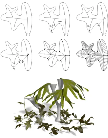
M¨undermann et al. [MMP03] extend the sweep method for lobed leaves defined from a branching skeleton. Their modeling process starts with a 2D silhouette of a leaf, which can be scanned or defined interactively using a curve edi-tor. The silhouette’s skeleton is then defined interactively or computed using a 2D Vorono¨ı diagram of the silhouette, and is represented as interconnected sticky splines [vO96] that preserve topological relationship during subsequent manipu-lation. The leaf surface is constructed by sweeping a cross-section between the skeleton and the silhouette. For this, the end and branching points of the skeleton are connected in a clockwise order to their closest points on the silhouette, forming segments of leaf. The segments are then subdivided into quadrilaterals (see Figure 15). So that, leaf texture can be subsequently applied.
The planar leaf model obtained in this way can be deformed in 3D space by functions that control its turning, bending and twisting along the axes of the skeleton. With such method, visually important aspects of leaf appearance can be captured and controlled interactively, allowing the design of a large variety of leaves (see Figure 15). It also gives a very good starting point for animation. It can be noted that the good visual quality of these models requires an important number of polygons that can become critical for rendering a big leafy tree, or a forest. In a next step of realism, Runions
et al. [RFL+05] proposed recently a class of biologically-motivated algorithms for generating leaf venation patterns (See Figure 16). Their algorithms simulate the development of veins by taking into account the hormone distribution process during leaf growth.
Realistic images of leaves requires a sophisticated shapes
Fig. 15. Construction of a sweep surface for lobed leaves [MMP03]. Left: Starting from a silhouette and a skeleton of a leaf, end and branching points of the skeleton are examined in a clockwise manner and connected to the silhouette. The resulting leaf segment are subdivided into quadrilateral. Right: A close-up scene of leaf models individually deformed from scanned images.
Fig. 16. Left: Wang et al. [WWD+05] introduced a parametric model
that describes leaves in terms of spatially-variant BRDFs and BTDFs and obtain realistic leaves images in realtime helped by graphics hardware. Right: Runions et al. [RFL+05] proposed recently a biologically-based simulation
for generating leaf venation patterns.
but also accurate appearance model and lighting computation. Thus, Wang et al. [WWD+05] describe leaf appearance in terms of a few parametric bidirectional reflectance distribution functions (BRDF1) and bidirectional transmittance distribu-tion funcdistribu-tions (BTDF2). These spatially-variant BRDFs and
BTDFs are compactly stored in a set of parameter maps, which can be loaded into graphics hardware for fast on-the-fly shading calculations. On real leaves, they measure the BRDF
1The BRDF is a function of incoming (light) direction and outgoing (view)
direction which describes how much light is reflected when light makes contact with a certain material.
2The BDTF is a function which describes how much light is crossing a
and BTDF which incorporate subsurface scattering inside leaf tissues and rough surface scattering on leaf surfaces. Their graphics hardware based algorithm extends the Pre-computed Radiance Transfer (PRT) approach to all-frequency lighting for leaves. In particular, it handles the combined illumination effects due to low frequency environment light and high-frequency sunlight by decomposing the local incident radiance of sunlight into direct and indirect components. The direct component, which contains most of the high frequencies, is evaluated on-the-fly using pre-computed light-visibility con-volution data.
IV. GLOBAL REPRESENTATIONS
Many of the current interactive applications such as virtual reality environments or computer games take place in outdoor scenes. Trees and plants are an essential part of these scenes. As shown in the previous section, detailed tree model are formed by such a vast number of primitives that real-time visualization of scenes with trees seems impossible on such bases. To alleviate this difficulty, simple global tree representa-tion, mainly based on images, have been developed to provide efficient rendering at distant views.
A. Billboard
Billboards are the most common tool for realtime rendering of forests. Thanks to their low cost, they are still considered the best choice in many recent industrial simulators. They are used in two different ways: classical billboards are small images that always face the camera (possibly with an axis constrained to be vertical) while cross billboards consist of two to four regular textured quads crossing each other. The first method shows no parallax when the camera moves, which is acceptable only in the case of objects symmetric around a vertical axis and grazing view angles. Moreover, a tree slightly behind another is likely to pop in front at a given angle. For this reason, billboard-based forests are usually sparse. The second method shows artifacts whenever one of the quads is seen at a grazing angle. In addition to the poor visual quality, billboards requires a pre-computation step of the plant images. Additionally, illumination is stored on the image leading to difficulties for dynamic lighting. For the same reason, animation of branches of leaves is not possible. Moreover, there is no simple Level-0f-Detail (LOD) scheme to gather individual billboards.
(a) (b) (c)
(d) (e)
Fig. 17. (a) billboards. (b) cross billboard. (c) 3-cross billboard. (d) 4-cross billboard. (e) billboard slices to represent crown foliage [Jak00].
B. Quadric Surfaces
Early global methods which do not have parallax problems induced by image based representation such as billboards was
proposed by Gardner in [Gar84]. His approach use textured quadric surfaces, like ellipsoids, bounded by an arbitrary number of planes to represent natural objects such as tree crowns. The global shape of the plant is then represented with a simple volumetric object with low cost while the irregularity of the density of foliage is still represented with procedural textures, applied to the surfaces. Various results with impressionist aspect are obtained as shown in Figure 18. However, due to its historical context, this work did not examine real time and animation rendering. Additionally, the textures seem difficult to parameterize to achieve more realistic results.
Fig. 18. Textured quadric surfaces [Gar84].
C. Basic Slicing
An other global solutions which gives some volume to the tree was proposed by Jakulin in [Jak00]. He extended the cross billboard representation to render the crown and combines it with traditional polygonal geometry rendering for the trunk and limbs of a tree. Indeed, the crown foliage is rendered using multiple parallel layers (slices) in the three orthogonal directions (see Figure 17.e). The group of slices for a specific view direction is called a slicing. During preprocessing, several sets of these slices are created from various view points. For each slicing, the primitives (i.e. individual leaves) are assigned to the closest slice. Each slice is then rendered to an individual texture. During rendering, the two slicings that are closest to the actual view direction are rendered simultaneously with correct transparency and blending.
The goal of this algorithm was to accommodate architec-tural walk-through and driving simulations. Therefore, viewing trees directly from above or below the tree is not supported. All slices are perpendicular to the ground plane, and blending between two sets provides sufficient coverage of the foliage. Notice that Section VI-A.2 presents related technique but with the benefic of levels of details and arbitrary viewpoints.
D. Extended billboard with depth and shading information
An other billboard-inspired technique is the one proposed by Qin et al. in [QNTN03] with the goal of fast rendering photo-realistic images of trees under various kinds of daylight. Their approach is to convert a 3D model of tree in a representation they named quasi-3D tree. A quasi-3D tree is a combination of 2D buffers which store geometrical and shading information of tree surfaces, i.e. their color (classic billboard), normal vectors, relative depth, and shadowing of direct sunlight and skylight.
In addition to these set of 2D buffers which are used to repre-sent the tree perpendicularly to the ground plane as billboard enriched with depth information, they store horizontal mask images for casting shadows (see Figure 19).
The shadows of direct sunlight and skylight are processed in two steps: self-shadow and external-shadow. Self-shadow, which is the most important shading information and the most time-consuming task, is examined in preprocess for different viewing directions, colors and positions of the sun. These different directions are chosen by the user to limit the amount of data to store (see Section V-B.3 describing [MNP01] for an automated version of this sampling). External-shadows, which depend on the circumstances, are constructed during the rendering process. The shadows, including umbrae and penumbrae, are examined by employing several shadow maps (named Sun-Shadow Buffers in the article) since light sources are the sun and the sky.
Using a two-step shadowing algorithm, this method can create high quality forest scenes illuminated by both sunlight and skylight at a low computation cost (few minutes on a Pentium III at 800Mhz). It can generate both umbrae and penumbrae on a tree casted by other trees and any other objects such as buildings or clouds. Transparency, specular reflection and inter-reflection of leaves, which influence the delicate shading effects of trees, can also be simulated with verisimilitude. Nevertheless, the drawback of billboards will be visible in animations when walking around a tree, walking through or over-viewing at a forest. Thus, they suggest to compute images viewed from multiple directions similarly to techniques presented in Sections V-B.2 and V-B.3.
+
Fig. 19. Top: 2D tree buffers with geometrical and shading information + horizontal mask images for casting shadows resulting in a rendered quasi-3D tree. Bottom: a resulting landscape. From [QNTN03].
TOWARDMULTISCALEREPRESENTATION
As one can see in previous sections, accurate modeling of plants and trees requires large number of primitives. A typical outdoor scene contains many plants and trees, each of them made of hundreds of thousands of primitives. Even with modern graphics rendering algorithm (using hardware acceleration or not), the rendering time of this large number
of primitives will not be acceptable. Moreover, the majority of objects in such scenes often cover only a few, or even a fraction of pixels on the screen, thus leading to use expansive anti-aliasing in the rendering. In contrast, global simplification method propose simple representation with a fixed level of details that look unrealistic at close view. To reduce the amount of rendered primitives representing a tree according to its visual importance without loosing realism, some multi-resolution or multiscale representations have to be setup.
Classical multi-resolution methods to reduce the number of polygons of an object using geometry-based simplification exist [HG97], [Hop98]. These methods, however, fail to cap-ture the nacap-ture of plants and trees. They tend to aggregate polygons from different leaves or different branches resulting in a smaller tree with a shape visually different from the original one. Moreover, this process also alters the lighting behavior of the tree, inducing non realistic popping artefacts. Several solutions dedicated to vegetation have been explored using various alternative graphic primitives. The structure of the tree play an important role on the possible simplification. Its multiscale hierarchy of components (generally defined by the branching order) define intuitively several levels of abstraction that can be used for simplification. Repetitive patterns of components can also be used to reduce the number of geometrical primitives to compute. The use of this type of structuring lead to a first category of multi-scale techniques presented in the next section. More generic methods build hierarchy of primitives by regrouping or merging them accord-ing to their spatial proximity. These methods are presented on Section VI.
V. MULTISCALE REPRESENTATIONS BASED ON PLANT STRUCTURE
As shown in Figure 20, tree structure is naturally hierarchi-cal. Thus, it is natural that many techniques based their hierar-chical representations (LOD) on it. This section describes this family of rendering techniques with a progression going from realtime and low memory consuming techniques to off-line and high level of realism.
Fig. 20. Trees structure is naturally hierarchical. Trees are composed of a trunk and main branches, which group small branches together. Boughs are made of leaves or needles; and leaves, needles, boughs, branches resemble each other. These properties allow many modeling simplifications.
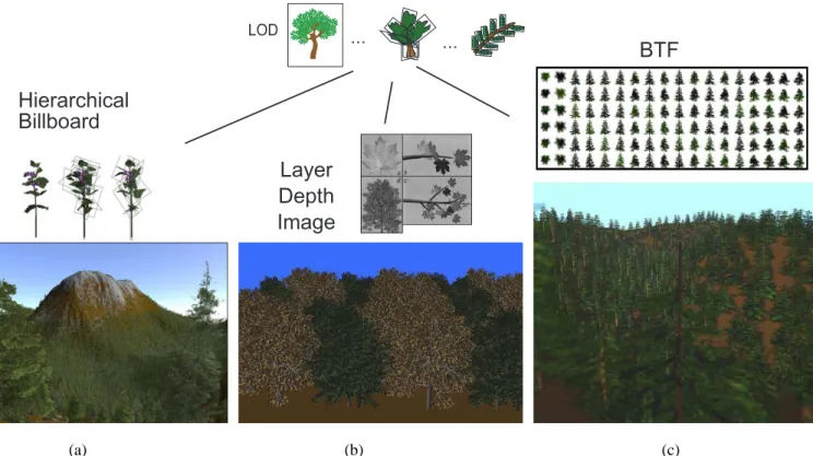
BTF
Layer
Depth
Image
Hierarchical
Billboard
... ... LOD (a) (b) (c)Fig. 21. The three main IBR families of LOD-scheme based on the structural nature of trees. At coarse level, the whole tree is represented by an IB primitive. At detailed level, each leaves is represented by an IB primitive. And at intermediate level, various branches are represented by IB primitives. The IB primitive can either be (a) billboard [BCF+05], (b) layered depth image [MDK99] or (c) either bidirectional texture [MNP01].
A. On the fly procedural generation
A natural way to build a multi-resolution representation is to include the simplification methods directly in the modeling process. Lluch et al. [LCV03] developed such an approach which they call procedural multi-resolution. They build pro-cedural models based on parametric L-systems that reflect a tree visual structure at different levels of resolution. They start from a parametric string representing a tree and generate a new string with embedded multi-resolution information. The algorithm is based on a metric that quantifies the relevance of the branches of a tree. This approach allows the generation of various trees in a forest, but the data storage is still an important issue.
If the generation process is fast enough to be done in realtime, an interesting idea is then to do it on the fly only when needed, avoiding so storage issue. It allows thus the rendering of incredibly complex and detailed scenes. This idea was first apply to terrain by fractal based modeling process. Perbet et al. [PC01], [GPR+03] generate and animate blades
of grass on-the-fly and only where the camera is looking. They use three levels of detail. Geometry and animation data related to grass are deleted once the camera is gone. Digiacomo et al. [GCF01] extend the idea to the animation and the interaction with trees: procedural method handles most of the trees efficiently, and physically-based method allows user interaction. Similar idea has been implemented in the commercial software [BD].
B. Image-based Representations
The good properties of an image to represent very complex objects with one single primitive can be used it in the case of trees. Various optimizations try to solve classical IBR issues (memory cost, static illumination, lack of relief, etc.). The use of the plant hierarchy to define several levels of IBR allows to bypass the issue of the fixed level of details of images. Figure 21 summarizes the three main existing approaches.
1) Hierarchical billboards or simplified textured trees: An
extension to the billboard approach presented in Section IV-A is to build a simplified tree with a few dozen to a few hundred polygons approximating the foliage distribution (see Figure 21.a) [BCF+05], [CCDH05], [IDV02], [BD]. A
hier-archy of LOD is built going from a simple billboard to trees with hundred polygons. Behrendt et al. built billboards of a tree by clustering elements of a same level in the hierarchy.
The first issue is the brutal transition from one level to another leading to popping effect. To decrease this phenomena, [IDV02] performs a per pixel transition: when the camera get further some pixels from fine polygons disappear by trans-parency and some others appear on a rough polygon. Thus, the number of polygons to render decreases. The second issue of this kind of approach is the static lighting encoded on images which can be tackle by storing a normal for each pixel and computing the shading during the rendering with a fragment program (per-pixel lighting). Note that this remains a coarse approximation. Simple animation of branches is possible only for near LOD. As results from [IDV02], [BCF+05] show a
of trees, in realtime and with dynamic lighting on NVidia GeforceFX graphics processor.
2) Hierarchical precomputed multi-Layer Z-buffers: Flat
images as billboards suffer from lack of relief. IBR techniques based on depth try to improve this [CW93]. Z-buffer images are pre-computed from different fixed viewing positions in order to reproject them and produce an image from a new viewpoint. Max et al. in [MO95], [Max96], [MDK99] derived this idea to tree. Z-buffer images are pre-computed for twigs and branches at various levels in the hierarchical structure of a tree (see Figure 21.b), and adaptively combined depending on the position of the new viewpoint. The pre-computed images contain multiple Z levels to avoid missing pixels in the recon-struction, subpixel masks for anti-aliasing, and colors/normals for shading after reprojection. If a subobject is too close to the viewpoint, the polygons of the original model are rendered. In [MDK99], they use the graphics hardware to perform the reprojection faster. As a result, they compute scenes like the one shown in Figure 21 which count ten millions of polygons in several minutes on SGI Onyx, InfiniteReality. The pre-computed data occupy around ten megabytes of texture memory.
3) Hierarchical bidirectional texture function: An other
way to limit the flatness effect of billboards is to fade nearest pre-computed views (see Figure 21.c) as described in [PCD+97] for any kind of objects. The set of pre-computed
views taken from various light direction is called Bidirectional Textures (BT) related to the Bidirectional Textures Function (BTF). This alpha blending between textures introduces a ghosting artifact and transparency variation (duplicated fea-tures) which show up when one moves around a tree: blending two half-faded textures is not equivalent to a single opaque texture. This can be limited by pre-computing a large set of views. Relying on even more images would correspond to bidirectional textures [SBLD03] and light-fields [LH96], [SGHS98]. But the huge amount of image data may not fit in the graphics memory.
Meyer et al. in [MNP01] apply this idea to trees which is well suited for instantiation and then limits the memory issue. Their data structure consists of a hierarchy of BT linked to a hierarchy of visibility cube-maps (6 shadow maps forming a cube surrounding an object) to compute the shadow. An example of hierarchy for a given tree can be a small branch plus its leaves (or needles), a larger branch, and the entire tree. A BT provides a billboard image of a shaded object (small branch, large branch or tree) for each pair of view and light directions. A BT is associated for each level of the hierarchy. The illumination reaching each tree elements is evaluated using the corresponding visibility cube-map. On SGI Onyx 2000, they achieve 7 to 20 fps fly-through of a scene with thousands trees with dynamic shading, self-shadowing and shadowing. The main drawback of their method is the amount of pre-computed data which lead to massively use instantiation and limit the diversity of trees.
C. Point and line based
In recent years, it has been shown in [MZG01], [RL00], [PZvBG00] that point-based rendering is a very efficient
means for the rendering of any complex geometry, idea supported by the efficient capacity of the hardware to treat it. This approach is based on the observation that in increasingly complex scenes triangles become smaller than a single pixel. In this case, triangle based scan-line rendering wastes time in superfluous sub-pixel computation. In opposite, points merge easily. The degree of detail can thus be fluently adapted by adding or removing single points.
1) Particle Systems: The forest model of Reeves et
al. [RB85] was probably a source of inspiration for many
works there after, especially on point-based representation. They primarily emphasized the forest environment instead of concentrating on the structural detail of individual plants. In addition, they focused more on the visual results than the specific details of actual botanical data. Results are very impressive at this time (see Figure 22.b), even if computing times were about several hours.
Their stochastic modeling approach, called particle systems, builds complex pictures from sets of simple, volume-filling primitives. The particle systems processes the trees in the data base serially; it generates a complete model for each tree and then renders the model. Starting with the main trunk, the algorithm constructs the tree by recursively generating sub-branches. The data structure for the model is a tree in which each node describes a branch segment. The structure is parsed and particles are drown into the frame buffer for each branch. In addition, they describe approximate and sto-chastic algorithms for shading. Probability of a particle to be shadowed or highlighted depends on its position in the crown. Highlights occur where the tree’s branches or leaves are exposed directly to sunlight i.e. close to the outer edge of the tree in the direction of the sun. For self-shadowing, the ambient and diffuse component drops off exponentially as d -the distance into the tree from the light source- increases as shown in Figure 22.a.
2) Realtime techniques: Later and as a natural evolution
of Reeves model, Weber et al. [WP95] and Deussen et al. in [DCSD02] present two models to render in real-time trees with a combination of polygons and points/lines representation. They also introduce the idea that best performance can be achieved if the plants are not uniformly simplified: hidden parts can be coarser than visible parts.
To be able to render a large number of trees, the rendering algorithm can progressively reinterpret the geometry of the tree: branches meshes as lines and leaf polygons as points. The geometry (polygons, points and lines) is stored in vertex arrays on the GPU. At far distance, some individual branches and leaves will simply disappear altogether in the Weber et
al. approach. This could lead to important visual artefacts.
Thus, Deussen et al. merge disappearing elements in larger primitives (points or lines) to better convey the shape in distant views. To select which part of the trees has to disappear, Weber
et al. use an automatic criteria on the size whereas Deussen et al. ask the user to make the selection during the modeling
process.
[DCSD02] showed scenes representing several tens of mil-lion of polygons rendered at interactive frame rate, with a NVidia Geforce3 graphics processor like the one presented in
(a)
(b)
(c)
(d)
(e)
d
Fig. 22. Techniques where LOD are based on the structural nature of trees and where the rendering primitive is the point and line. Early [RB85] introduced
(b) a particle-based rendering technique associated with (a) a stochastic shadowing where the portion of received light is function of the distance to the hull.
With distance (c) [WP95] and (d)(e) [DCSD02] progressively re-interpret the tree: branches meshes as lines and leaf polygons as points.
Figure 22. The detail can also be increased automatically for high resolution images. To improve realism, these approaches allows to implement a wind effect by moving the trees elements during the rendering. And shadowing within the trees can be produced using a standard shadow map technique [RSC87].
D. Illumination based
Beside the rendering primitive type, computer graphics researchers works on illumination model. An interesting idea is to replace the indistinguishable data by a fuzzy primitive that would reproduce the same photometric behavior of the geometry it represents. This idea is used in many generic computer graphics models for surface or volume [Bli77], [Bli78], [Bli82]. In the specific case of trees, geometric details like needles or leaves are so small that they usually cannot be seen except for the nearest trees. Thus, it is a well suited case to develop shaders. Moreover, photo-realistic images can be obtained by a global illumination simulation. Thus, some works search to perform this heavy simulation to trees scenes.
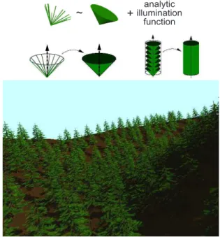
1) Shaders of needles branches: Meyer and Neyret in
[MN00] proposed primitives and shaders at several scales for the particular case of the pine-tree or fir-tree as shown in Figure 23. Depending on the distance, the primitive they consider is either the needle (level 1), the cone (level 2), or the bough (level 3). They computed an analytical formula representing the global reflectance and opacity at each of those levels, including the internal shadows. They use several approximation and optimization to simplify and compute the formula. The analytical properties of this set of three shaders allow to represent at various scales the cumulated effects of the smaller scales, without sampling them. In particular, it includes the internal shadows, and takes the visibility into account.
They implemented this model in a cone-tracer which reduce drastically the number of traced ray: direct rays and shadow rays. As results, images of hundred fir-trees were computed in around 10 minutes on SGI Onyx2, which was ten time faster than the classical ray-tracer Rayshade. The major issue of this approach is the difficulty to extend it to other family because of the pre-condition of strong a priori knowledge on the matter distribution which is not available for many object.
~ illuminationanalytic function
+
Fig. 23. [MN00] proposes three levels of analytical shaders in order to represented complex geometric structure such as branches of pine-trees. The analytical aspect allows fast computation without sampling and low aliasing in a cone-tracer renderer.
2) Global illumination: Radiosity is a global illumination
methods. Each polygon has radiative properties and contributes to illumination of all other polygons of the scene. Thus, the basic resolution quadratically depends of the number of considered elements, and is particulary expensive in memory and computation time. To limit this cost, techniques build hier-archical clusters replacing a group of geometric objects with a simple shape with equivalent radiative properties [Sil95]. The exchange of energy between each pair of elements are computed at the high level of the hierarchy. This method allows to adapt the complexity of the system to resolve: the choice of the depth in the hierarchy at which the system is resolved is a compromise between precision of the solution and computation time. However, such methods are limited in scene size because of the super linear amount of memory they
require in terms of the number of input polygons.
Various techniques exists to automatically build the clus-ters hierarchy from polygonal representations. The main one consists of decomposing the space into an octree, recursively defined as voxels of variable sizes [Sil95]. The sizes of the voxels are defined to fit the local irregularity of the shapes. Soler et al. in [SSBR03] take advantage of the structuring and the self-similarity of the plants, to propose another de-composition of the space that minimize the number of cluster and allows instantiation. The clusters are used to replace the branching systems at the different levels of hierarchy in the plant structure. The same cluster, used as reference for different parts of the plant model, contains reflectance and transmittance functions simulating the energy resulting of interaction of the real geometry with lights from all directions. Such functions are costly to handle, both in term of computa-tion times and storage. However, use of those meta-objects is especially useful in case of high degree of self-similarity in the model like in plants. With instantiation, gains on memory and computation time are important on their examples compared to classical hierarchical radiosity.
VI. MULTISCALE REPRESENTATIONS BASED ON RULES: SPATIAL PROXIMITY AND VISIBILITY
LOD construction based on the structure of trees has the main advantage to allow simplification on less important parts. Nevertheless, it implies strong coordination with the modeling process which can be tricky. We review in this section tech-niques basing LOD construction on arbitrary rules which have the main advantage to be disconnected from the modeling. Those techniques allow unstructured input like polygon soup and then build a hierarchy independent of the tree one. Rules on spatial proximity or on visibility are developed. We present techniques based on two well known data structure, octree in Section VI-A and BSP in Section VI-B. In Section VI-C, we give an overview of two techniques based on distance between objects and on visibility. As a consequence, structured-based LOD techniques are often linked to a specific modeling process whereas techniques based on rules converting any kind of input are more practical.
A. Octree and slicing
Octree data structure can be coupled with various rendering primitives as illustrated in Figure 24.
1) Ray-traced volumetric texture: Volumetric textures
ap-proach introduced by Kajiya et al. [KK89] to represent fur, consists of mapping a 3D layer on a surface using a 3D data set as texture pattern. This is especially adapted to a layer of continuous vegetation covering a landscape as well as many other objects like fur, organic 3D textures, etc. The key idea is to represent the 3D material by a cubic reference volume, to be mapped onto a surface (like a thick skin). The copies of the reference volume, named texels, are fitted upon the surface and are deformed in order to stick to each other. The reference volume is a 3D arrays of voxels. Each voxel encode the local geometry by specifying an opacity, a frame
and the reflectance function. The rendering is done by ray-tracing, which becomes a volumetric ray-tracing when a texel is crossed. Whereas illumination function of Kajiya is specific to fur, Neyret in [Ney95], [Ney96], [Ney98] propose a generic one which allowed him to render nice images of forest as the one shown in Figure 24. Ray tracing rendering took only several minutes on SGI Indy. Notice that representing the small data by a reflectance model is related to the shader approach presented in a structural scheme Section V-D.1.
2) Real-Time volumetric texture by slicing: The ray-traced
volumetric approach inspired real-time technique [MN98], [LPFH01]. To rely on hardware acceleration the volume is rendered using textured slices. This has nice properties: the parallax is perfect because the generated fragments are really 3D (i.e., at their proper depth), and the filtering is smoothly managed by the texture hardware. Few polygons (64 in [MN98]) are required for a portion of material. On the other hand, the slicing must be adapted to the viewpoint otherwise one could see between the slices at grazing angles. Moreover, the needed amount of texture memory limits the number of slices and leads thus to a repetitive aspect of the global scene. Decaudin et al. in [DN04] specifically adapt it to forest. Their approach is based on repeated instances of patterns with a prism shape (called texcell): a base triangle on the ground vertically extruded. They use two different kinds of texcell. A simple one (regular texcell) where slices are parallel to the ground which gives good quality and efficiency for most location except for grazing view angle. The other one, the silhouette texcells (more expensive) are sliced parallel to the screen and used near the landscape silhouette. Their texcells store a small part of forest (tens of trees) as a 3D texture on the graphic board. They filter it non-linearly by adapting the number of slices to the distance (LOD). They also define an aperiodic mapping of the texcells in the spirit of [NC99] by creating several edge-matching patterns. Their results show complex terrains with several tens of thousand trees at interactive frame rate. In [FPF04], they present a per pixel shading approach to allow dynamic lighting. Notice, that [BCF+05] use a similar approach for their far LOD.
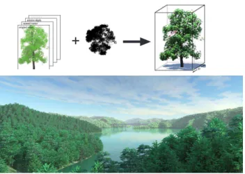
3) Volumetric image-based representation reconstructed from photographs : Still in the grid approach family, Reche et al. [RMD04] tackled the challenging problem of
reconstruct-ing and renderreconstruct-ing a tree from photographs. Thus, on each cell of a recursive grid, they estimate an opacity value and a set of textures from the calibrated pictures. On the recursive grid, the opacity of the cells are computed by an optimization process: cells opacity must match the alpha-mattes (cumulative opacity at the pixels) extracted from the photographs. In each cell, this opacity value is associated to a set of textures extracted from photographs (one texture from each view), which is used as a view-dependent texture during the rendering. Each grid cell is rendered as an alpha blended billboard attached to his center. Basically, each billboard is a view-dependent texture with transparency. Indeed, billboard is textured by the blend (multi-texturing) of the two textures corresponding to the two closest cameras. For the rendering of the whole tree, the algorithm traverse the cells back-to-front, and render the billboard for each cell.
Primitive in each voxel
=
small billboard
(built from photos)
Rendering by slice
Primitive in each voxel
=
point
Primitive in each voxel
=
opacity +
reflectance function
1 slice = 1 mipmapped
textured polygon
Rendering at voxel level
(a) (b) (c) (d)
Fig. 24. Most techniques basing LOD construction on arbitrary rules use the spatial proximity to regroup primitives. Thus, octree is a well-suited data structure. On each voxel the rendering primitive differs: (a) shaders [Ney98], (b) point [DVS03] and (c) billboard [RMD04]. In (d), by considering stack of plan in the octree, [DN04] renders a portion of forest with a stack of textured polygon.
As result, the volumetric tree structure allows interactive rendering of realistic 3D trees. Nevertheless, two limitations can be mentioned. First, the method is efficient only on trees with relatively sparse foliage since photographs of such trees typically have single pixels containing the blended projection of numerous leaves/branches and background. It is difficult to capture inside parts of dense trees. Second, it is very difficult to capture the top of the trees which is important in landscape rendering with flying movement.
4) Volumetric point-based representation: Stamminger et al. in [DVS03] introduced the sequential point trees data
structure which is basically an octree where each cell is a point. In a point-based rendering scheme, this spatial based approach is related to the structural one presented in Section V-C. Their algorithm is not specific to trees but they mainly illustrate it with an outdoor scene including trees. It begins with a set of uniformly distributed point samples on the object (like in [SD01]), which are inserted into an octree to form a point hierarchy. Position and normal values of the children are averaged to obtain the values for the inner nodes. An inner node in the hierarchy represents the union of all its children, so the diameter monotonically increases when going up the hierarchy. The originality of the paper is that the hierarchical rendering traversal of this data structure is replaced by smart sequentialized process on the graphics processor, while the CPU remains available for other tasks. Their result shows a scene with various models including around tens of complex trees. Close views run at interactive frame rate with an ATI Radeon 9700.
B. Binary space partitioning
Marshall and Fussel in [MFI97] propose a multiresolution rendering system that compiled a given botanical description of a plant into a hierarchal volume approximation based on irregular tetrahedra. This is used in an adaptive volume refinement which creates a binary space partitioning (BSP) tree. The partitioning of the space with tetrahedra allows a more adaptive subdivision method than is possible with octrees. Their system is designed for rendering very large collections of randomly parameterized plants.
The procedural volumetric plant model used can be de-veloped at various levels of details and memory usage. The generation of actual geometry for any subvolume can be delayed until it is needed. This drastically reduces memory consumption and initialization time, as the binary tree does not need to be built fully (idea related to Section V-A). This compilation process begins with a full tetrahedral volume as a first approximation to an object, which is then further refined recursively as needed to accommodate individual tree modules. During rendering, explicit polygon are generated for objects that are close to the viewer, while for objects hidden or further away, the bounding tetrahedra are rendered with shading properties approximating their contents as groups of microsurfaces. Result can be seen in Figure 25 on the right. To compute it, software implementation needs several minutes of computation on SPARC Center 2000E. A shading is computed on each vertices.
![Fig. 2. Left: Branching point geometry with circular polyhedron according to Kawaguchi [Kaw82]](https://thumb-eu.123doks.com/thumbv2/123doknet/13502340.415281/5.918.510.803.77.251/left-branching-point-geometry-circular-polyhedron-according-kawaguchi.webp)
![Fig. 8. Implicit representation of a poplar tree with smooth and non smooth blending [GMW04a].](https://thumb-eu.123doks.com/thumbv2/123doknet/13502340.415281/6.918.509.797.644.1029/fig-implicit-representation-poplar-tree-smooth-smooth-blending.webp)
![Fig. 11. Top: Displacement maps for bark. From [WWT + 03]. Bottom:](https://thumb-eu.123doks.com/thumbv2/123doknet/13502340.415281/8.918.120.403.76.466/fig-displacement-maps-bark-wwt.webp)
![Fig. 18. Textured quadric surfaces [Gar84].](https://thumb-eu.123doks.com/thumbv2/123doknet/13502340.415281/10.918.78.440.886.979/fig-textured-quadric-surfaces-gar.webp)