HAL Id: hal-01652212
https://hal.archives-ouvertes.fr/hal-01652212
Submitted on 30 Nov 2017HAL is a multi-disciplinary open access archive for the deposit and dissemination of sci-entific research documents, whether they are pub-lished or not. The documents may come from teaching and research institutions in France or abroad, or from public or private research centers.
L’archive ouverte pluridisciplinaire HAL, est destinée au dépôt et à la diffusion de documents scientifiques de niveau recherche, publiés ou non, émanant des établissements d’enseignement et de recherche français ou étrangers, des laboratoires publics ou privés.
A hybrid system for battery thermal management for
electric vehicles
Lucia Ianniciello, Pascal Henry Biwole, Patrick Achard
To cite this version:
Lucia Ianniciello, Pascal Henry Biwole, Patrick Achard. A hybrid system for battery thermal manage-ment for electric vehicles. European Battery, Hybrid and Fuel Cell Electric Vehicle Congress , Mar 2017, Genève, Switzerland. �hal-01652212�
European Battery, Hybrid and Fuel Cell Electric Vehicle Congress
Geneva, 14
th- 16
thMarch 2017
A HYBRID SYSTEM FOR BATTERY THERMAL
MANAGEMENT FOR ELECTRIC VEHICLES
Lucia Ianniciello
1**, Pascal Henry Biwolé
1,2, Patrick Achard
11
MINES ParisTech, PSL Research University PERSEE – Center for Processes, Renewable Energies and Energy Systems, CS 10207, F-06904 Sophia Antipolis, France
2
Université Côte d’Azur, J-A Dieudonné Laboratory, UMR CNRS 6621, 06108 Nice, France
Abstract
Electric cars are limited by the performances of Li-ion batteries. Usually, air or coolant circulation systems are employed as battery thermal management systems. The disadvantages of those systems are their complex implementation, their cost and the phantom electric load. Phase change materials (PCMs), represent a promising solution to achieve passive thermal management. The challenge of this solution is to quickly release the thermal energy stored in the PCMs. A solution proposed is the incorporation of an additional system to discharge the PCM. This hybrid system is presented in this paper.
Keywords: thermal management system; phase change materials; latent heat storage; semi-passive system.
Nomenclature
Symbols:
B0 phase change function
B1 smoothed phase change function Cp specific heat, J.kg-1.K-1
dPCM PCM thickness, m
D smoothed Delta Dirac function e intercells gap, m
g gravitational constant, m.s-2
h forced convection coefficient, W.m-2.K-1 k thermal conductivity, W.m-1.K-1
LF latent heat of fusion, J.kg-1 m mass, kg
P pressure, Pa
Qbattery heat generated in the cell, J t time (h) T temperature, K Tm melting temperature, K T0 initial temperature, K u speed, m/s Greek letters:
β coefficient of thermal expansion, K-1 ΔT temperature difference, K
µ dynamic viscosity, Pa.s ρ volumic mass, kg.m-3 Subscript / Exponent: liquid liquid phase max maximal solid solid phase sol solidification air air
1 Introduction
The market development of electric cars is viewed as a key asset to deal with global warming and to decrease car pollution [1]. The performances of the car and specifically of the battery system are currently limited compared to the internal combustion engine car. Electrochemical batteries are expensive and have a lower autonomy and a shorter lifespan. In
addition, the time needed to recharge a battery is longer than to fill up at the gas pump.
The most promising battery for electric vehicles application is the Li-ion battery as it is the one that can permit a larger capacity, a greater autonomy and a longer lifespan [2]. Lithium ion batteries can overheat during charge or discharge when the intensity or the ambient temperatures are too high. Inside a battery pack, there can be a non-uniform temperature distribution. This can result in a
localized deterioration and will eventually lead to a general deterioration of the entire pack. Therefore, in the case of Li-ion batteries it is important to keep the temperature under a given value and to have a uniform temperature field [3]. The optimal temperature range is between 15 and 35°C. If the temperature goes under 15°C, there is a diminution of the battery capacity and of its performances. If the temperature goes over 35°C, there will be irreversible reactions which will lead to a diminution of the battery lifespan. Battery thermal management, as air or coolant circulation systems, is necessary for this type of batteries [3]. The main issues with these systems are their complex implementation, their cost, their lack of reliability and most of all, the fact that they constantly use electricity to ensure the thermal management of the battery even when the car is parked.
Latent heat thermal energy storage (LHTES) through the use of phase change materials (PCMs), represents a way to achieve passive thermal management. PCMs could be cheaper and easier to operate. They can ensure a better autonomy and a better lifespan of the battery by ensuring the battery temperature stays in the desired optimal range [4]. Several studies ([4], [5], [6], [7]) have been conducted on the integration of PCMs to ensure the thermal management of Li-ion batteries. One of the key issues raised by those studies is the difficulty to release the thermal energy stored in the PCMs before the application of the next thermal load [8]. A solution to this problem is often the use of hybrid heat sinks incorporating an additional system to discharge the PCM [9].
load [8]. A solution to this problem is often the use of hybrid heat sinks incorporating an additional coolant used to discharge the PCM [9] This paper presents the evaluation of such a hybrid thermal management system. The system is composed of a PCM to cope with the thermal load and a forced air circulation which starts
when the PCM is entirely melted. The first section of this paper introduces the objectives of our work. The second section details the methodology and the case study we have chosen. The third section presents the results. Last, the fourth section discusses the results.
2 Objectives
The performances of a battery can be significantly improved if the battery temperature is maintained in a specific range. In fact, when the battery is kept between 15°C and 35°C the lifespan is longer and the autonomy experiences a minor decrease (Figure 1). The aim of the study is to assess if this semi passive thermal management system can maintain the battery below 25°C for one or multiple cycles. Therefore, the capacity of the system to crystallize the PCMs after a thermal load is estimated.
3 Methodology and case study
Models representing three prismatic battery cells surrounded by a layer of PCM and forced air cooling have been developed. The thermoconvective transfers have been numerically resolved by transient studies using quadratic finite elements.
The size of a battery cell is: 147.8 mm x 91 mm x 26.8 mm.
The thermal load applied to the battery cells represents a WLTP (Worldwide harmonized Light vehicles Test Procedure) cycle followed by the equivalent discharge associated with 10 min driving on a highway. The total amount of heat generated to be extracted by this cycle is 15 kJ. One cycle lasts 2500 s (41 min 40 s). If there is no thermal management system, the temperature of one cell at the end of the cycle would be 40°C, if the initial temperature is 20°C.
Figure 2: Thermal load and air speed
The PCM considered is based on fatty acids and is produced from plants. Its phase change temperature from solid to liquid is 21.5°C. The quantity of the PCM needed is 65 g for one cell, as calculated by Equation 1. F PCM m solid PCM PCM battery m Cp T T m L Q , ( 0) (1)
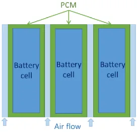
The PCM surrounds the cells as shown on Figure 2. If the PCM thickness is 2 mm the mass of the PCM would be 80 g per cell. Different thicknesses of PCM and air gap between the cells were tested to compare the battery maximal temperature and the time required to crystallize the PCM (Table 1).
The forced air circulation operates only when the PCM is entirely melted. The air inlet temperature is 20°C. The air inlet velocity is set to 5 m/s. The air circulates in forced convection all around the PCM.
Figure 2: Schematic view of the system
Table 1: Mass of the PCM corresponding to the thickness Thickness (mm) 1.0 1.5 2.0 2.5 3.0 Mass of PCM per cell (g) 39 60 80 102 124
4 Mathematical model
The model has been developed on COMSOL Multiphysics. The mathematical model can be divided in two parts: the model of the heat transfer between the battery cell, the PCM and the air and the phase change of the PCM.
4.1 Heat transfer
The conductive and convective heat transfers are considered and the radiative heat transfer is neglected. The energy equation, continuity equation and momentum equation are employed (2, 3 and 4). The convection is localized on the boundaries in contact with the air. The natural convection in air is neglected (Gr/Re²<1). The convection in the PCM is neglected, the velocity field u is equal to zero for the PCM.
Q
T
T
u
t
T
C
p
)
.(
)
.
(
(2)0
.
u
(3) u µ T T g P u u t u ² . ) ( ) . ( 0
(4)The boundaries are adiabatic except at the inlet/outlet of air. The ambient temperature is set to 20°C and the inlet air temperature is 20°C.
4.2 PCM phase change
A function, B0, is defined representing the liquid fraction of the PCM (equation 5). The function B0 is approximated by a second order differential equation B1 to ensure the second order differentiability. B1 is employed in the definition of the PCM volumic mass and thermal conductivity as shown on equation 6 and 7. A function D is defined for the expression of the heat capacity of the PCM. D is a smoothed Delta Dirac function which permits to equally distribute the latent heat around the melting point (equation 8). The heat capacity is defined with the functions B1 and D (equation 9). 0 1 2 3 4 5 0 2 4 6 8 10 12 14 0 1 2 3 S p ee d (m /s) P (W ) Time (h) Qbattery vair(m/s)
) ( , 1 ) ( ) , 2 ) ( , 0 ) ( 0 T T T T T T T T T T T T T T T T B m m m m m (5) ) ( ) ( )
(T
solid
liquid
solid B1 T
(6))
(
)
(
)
(
T
k
k
k
B
1T
k
solid
liquid
solid
(7) ) ( ) ( , )² 4 / ( ) )² 4 / ( ) ( exp( ) ( ), ( , 0 ) ( 2 T T T T T T T T T T T T T T T T D m m m m m (8) ) ( ) ( ) ( ) (T C C C B1T L DT
Cp psolid pliquid psolid F (9)
The convection in the PCM is neglected. In fact, the container of the PCM is so thin that there will be hardly a movement of the PCM.
5 Results
The model has been made for the different cells spacing and PCM thicknesses.
5.1 PCM thickness
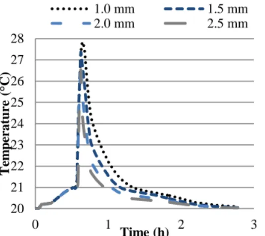
The influence of the PCM thickness has been represented on Figure 3 and 4 for a cells spacing of 2.5 mm. As expected increasing the amount of PCM makes the battery maximal temperature decrease. However it extends the time necessary to discharge the PCM.
Figure 3: Cell temperature for an inter-cells gap of 2.5 mm
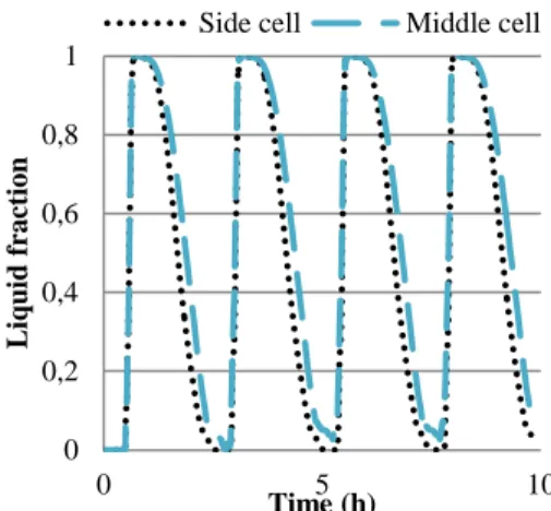
Figure 4: PCM liquid fraction for an inter-cells gap of 2.5 mm
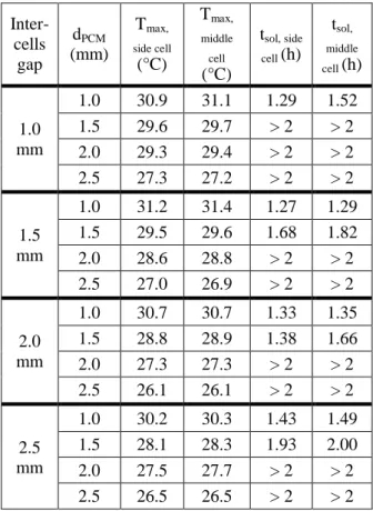
Moreover, this disposition with 3 cells shows that the middle cell’s PCM crystallization time is higher than for the side cell. The temperature of the side cell and the middle cell are quite the same. All the values of maximal cell temperature and PCM crystallization time are in Table 2.
Table 2: Results for all the cell spacing and PCM thicknesses Inter-cells gap dPCM (mm) Tmax, side cell (°C) Tmax, middle cell (°C) tsol, side cell (h) tsol, middle cell (h) 1.0 mm 1.0 30.9 31.1 1.29 1.52 1.5 29.6 29.7 > 2 > 2 2.0 29.3 29.4 > 2 > 2 2.5 27.3 27.2 > 2 > 2 1.5 mm 1.0 31.2 31.4 1.27 1.29 1.5 29.5 29.6 1.68 1.82 2.0 28.6 28.8 > 2 > 2 2.5 27.0 26.9 > 2 > 2 2.0 mm 1.0 30.7 30.7 1.33 1.35 1.5 28.8 28.9 1.38 1.66 2.0 27.3 27.3 > 2 > 2 2.5 26.1 26.1 > 2 > 2 2.5 mm 1.0 30.2 30.3 1.43 1.49 1.5 28.1 28.3 1.93 2.00 2.0 27.5 27.7 > 2 > 2 2.5 26.5 26.5 > 2 > 2
The simulations show that this system is able to keep the battery in a small temperature range for one cycle. However the time necessary to release the thermal energy stored in the PCMs is too long
20 22 24 26 28 30 32 0 1 2 3 Te m p er a tu re ( °C) Time (h) 1.0 mm 1.5 mm 2.0 mm 2.5 mm 3.0 mm 0 0,2 0,4 0,6 0,8 1 0 1 2 3 Liq u id fr a ctio n Time (h) 1.0 mm 1.5 mm 2.0 mm 2.5 mm 3.0 mm
in most of the cases. In fact, in order to keep the battery temperature low a large quantity of PCM has to be employed. The regeneration of this quantity of PCM is difficult. A compromise has to be made between the battery maximal temperature and the time required for the PCM regeneration.
5.2 Cells spacing
The cells spacing have a less remarkable influence. The comparison of the cell spacing for a given PCM thickness is shown on Figure 5 and 6. Figure 7 represents the air temperature in the ducts for the different inter-cells gap. As expected the air temperature is higher for smaller gaps.
Figure 5: Cell temperature for a PCM thickness of 1.0 mm
Figure 6: PCM liquid fraction for a PCM thickness of 1.0 mm
Figure 7: Average air temperature for a PCM thickness of 1.0 mm
5.3 Test on several cycles
A simulation was made on four cycles. The cycles were alternating thermal load and air flow. The thermal load is the same, lasting 2500 s and the air flow lasts 1 hour and 45 minutes. On Figures 8 and 9 are represented the evolution of the cell temperature and the PCM liquid fraction. The cycles can be clearly seen the cycles on the graphics. After the first cycle the cell temperature do not decrease to 20°C but to 21°C which leads to a higher temperature at the end of the second thermal load. However, the PCM can crystallize totally on the side cell and almost totally for the middle cell. Then for the three last cycles the temperature stays the same.
Figure 8: Cell temperature for 4 cycles 20 22 24 26 28 30 32 0 1 2 3 Te m p er a tu re ( °C) Time (h) 1.0 mm 1.5 mm 2.0 mm 2.5 mm 0 0,2 0,4 0,6 0,8 1 0 1 2 3 Liq u id fr a ctio n Time (h) 1.0 mm 1.5 mm 2.0 mm 2.5 mm 20 21 22 23 24 25 26 27 28 0 1 2 3 Te m p er a tu re ( °C) Time (h) 1.0 mm 1.5 mm 2.0 mm 2.5 mm 20 22 24 26 28 30 0 5 10 Te m p er a tu re ( °C) Time (h)
Figure 9: PCM liquid fraction for 4 cycles
6 Discussion
This simple system does not permit to maintain the temperature of the battery pack in the desired range thanks to the PCM for multiple loading cycles. The better temperature obtained is for the cells spacing of 2.0 mm and the PCM thickness of 2.5 mm. But the time to regenerate the PCM is too long. The problem of the PCM regeneration is caused by the low surface exchange given by this system between the PCM and the air. In order to solve this issue a solution is to increase the heat exchange surfaces. This way there will be a better thermal transfer between the PCM and the air. The geometry has to be improved in order to get a more efficient system.
The configuration one can choose is the one with a cell spacing of 2.0 mm and a PCM thickness of 1.5 mm. With this configuration the maximal cell temperature is around 29°C for one cycle and the time to solidify the PCM is around 1 h and 30 min.
7 Conclusion
This system permits to decrease considerably the battery maximal temperature. However, the temperature stays too high according to our specifications. We could add more PCM but then the PCM regeneration time would be too long. A solution could be to increase the heat transfer surface between the PCM and the air. Another solution would be to enhance the PCM and the air thermal conductivities.
References
[1] E. Ferrero, S. Alessandrini, and A. Balanzino,
“Impact of the electric vehicles on the air pollution from a highway,” Applied Energy, vol. 169, pp. 450–459, May 2016.
[2] R. K. S. Al-Hallaj, “Passive thermal management
using phase change material (PCM) for EV and HEV Li- ion batteries,” p. 5 pp., 2005.
[3] T. Zhang, C. Gao, Q. Gao, G. Wang, M. Liu, Y.
Guo, C. Xiao, and Y. Y. Yan, “Status and development of electric vehicle integrated thermal management from BTM to HVAC,”
Applied Thermal Engineering, vol. 88, pp. 398–
409, Sep. 2015.
[4] S. A. Khateeb, M. M. Farid, J. R. Selman, and S.
Al-Hallaj, “Design and simulation of a lithium-ion battery with a phase change material thermal management system for an electric scooter,”
Journal of Power Sources, vol. 128, no. 2, pp.
292–307, Apr. 2004.
[5] C.-V. Hémery, F. Pra, J.-F. Robin, and P. Marty,
“Experimental performances of a battery thermal management system using a phase change material,” Journal of Power Sources, vol. 270, pp. 349–358, Dec. 2014.
[6] Z. Ling, J. Chen, X. Fang, Z. Zhang, T. Xu, X.
Gao, and S. Wang, “Experimental and numerical investigation of the application of phase change materials in a simulative power batteries thermal management system,” Applied Energy, vol. 121, pp. 104–113, May 2014.
[7] A. Babapoor, M. Azizi, and G. Karimi, “Thermal
management of a Li-ion battery using carbon
fiber-PCM composites,” Applied Thermal
Engineering, vol. 82, pp. 281–290, May 2015.
[8] A. Mills and S. Al-Hallaj, “Simulation of passive
thermal management system for lithium-ion battery packs,” Journal of Power Sources, vol. 141, no. 2, pp. 307–315, Mar. 2005.
[9] Z. Ling, F. Wang, X. Fang, X. Gao, and Z.
Zhang, “A hybrid thermal management system for lithium ion batteries combining phase change materials with forced-air cooling,” Applied
Energy, vol. 148, pp. 403–409, Jun. 2015.
[10] Ahmad Pesaran, “Tools for Designing Thermal Management of Batteries In Electric Drive Vehicles,” Pasadena, CA, 04-Feb-2013.
Authors
Lucia Ianniciello graduated from ENSIACET (Ecole Nationale Supérieure des Ingénieurs en Arts
Chimiques et Technologiques) in chemical
engineering in 2014. Since April 2015, she is a Ph.D. candidate in the center PERSEE (Center for Processes, Renewable Energies and Energy Systems) in Sophia Antipolis in France. The subject of the thesis is the dynamic study of a battery thermoregulated by phase change materials for the EVs. The thesis is supervised by Patrick Achard and Pascal Henry Biwolé.
Pascal Henry Biwolé graduated from the Special Military Academy of St-Cyr Coëtquidan in 2002. He holds a PhD degree in Civil Engineering obtained in 2009 in the French National Institute of Applied 0 0,2 0,4 0,6 0,8 1 0 5 10 Liq u id fr a ctio n Time (h)
Sciences of Lyon, and a research directorship habilitation from the University of Nice Sophia Antipolis obtained in 2016. He is currently associate professor at the University of Nice Sophia Antipolis and research associate at Mines ParisTech, Center for Processes, Renewable Energies and Energy Systems. He is the director of the Smart Buildings Department of the Engineering School of the University of Nice Sophia Antipolis since 2012.
Patrick Achard has an engineer diploma (Arts &
Métiers ParisTech, Paris 1977) with a specialization in materials. He holds a Phd in energetic (Mines ParisTech, Sophia Antipolis 1986) and obtained an Habilitation in Energetics (INPG, Grenoble,1995). He founded the research group EM&P (Energetics, Materials and Processes) in 1990 and led it until 2010. He is presently a Research Director within PERSEE. He contributed as an editor to the European Passive Solar Handbook (1997) and to the Handbook of Aerogels (Springer, 2011)). He is author of 45 publications, is cited as an inventor in 14 patents, and has directed 25 Phd students.
![Figure 1: Battery power curves in charge and discharge depending on the temperature [10]](https://thumb-eu.123doks.com/thumbv2/123doknet/13527733.417584/3.892.249.659.912.1088/figure-battery-power-curves-charge-discharge-depending-temperature.webp)