HAL Id: hal-02529078
https://hal.archives-ouvertes.fr/hal-02529078
Submitted on 2 Apr 2020
HAL is a multi-disciplinary open access
archive for the deposit and dissemination of
sci-entific research documents, whether they are
pub-lished or not. The documents may come from
teaching and research institutions in France or
abroad, or from public or private research centers.
L’archive ouverte pluridisciplinaire HAL, est
destinée au dépôt et à la diffusion de documents
scientifiques de niveau recherche, publiés ou non,
émanant des établissements d’enseignement et de
recherche français ou étrangers, des laboratoires
publics ou privés.
Dynamic path planning for percutaneous procedures in
the abdomen during free breathing
Danial Pour Arab, Sandrine Voros, Caroline Essert
To cite this version:
Danial Pour Arab, Sandrine Voros, Caroline Essert. Dynamic path planning for percutaneous
proce-dures in the abdomen during free breathing. International Journal of Computer Assisted Radiology
and Surgery, Springer Verlag, In press. �hal-02529078�
(will be inserted by the editor)
Dynamic path planning for percutaneous procedures
in the abdomen during free breathing
Danial Pour Arab · Sandrine Voros · Caroline Essert
Received: date / Accepted: date
Abstract
Purpose Percutaneous procedures are increasingly used for the treatment of tu-mors in abdominal structures. Most of the time, these procedures are planned based on static preoperative images, and do not take into account any motions, while breathing control is not always applicable. In this paper, we present a method to automatically adjust the planned path in real time according to the breathing. Methods First, an estimation of the organs motions during breathing is per-formed during an observation phase. Then we propose an approach named Real Time Intelligent Trajectory (RTIT) that consists in finding the most appropriate moments to push the needle along the initially planned path, based on the motions and the distance to surrounding organs. We also propose a second approach called Real Time Straight Trajectory (RTST) that examines sixteen scenarios of needle insertion at constant speed, starting at eight different moments of the breathing cycle with two different speeds.
Results We evaluated our methods on six 3D models of abdominal structures built using image datasets and a real-time simulation of breathing movements. We measured the deviation from the initial path, the target positioning error, and the distance of the actual path to risky structures. The path proposed by RTIT approach is compared to the best path proposed by RTST.
Conclusions We show that the RTIT approach is relevant and adapted to breath-ing movements. The modification of the path remains minimal while collisions with obstacles are avoided. This study on simulations constitutes a first step towards intelligent robotic insertion under real-time image guidance.
Keywords Intraoperative path planning · Percutaneous procedure · Ablation therapy
D. Pour Arab · C. Essert
ICube Laboratory, Universit´e de Strasbourg / CNRS, Strasbourg, France E-mail: [email protected], [email protected]
S. Voros
TIMC-IMAG Laboratory, Grenoble, France E-mail: [email protected]
1 Introduction
Image-guided percutaneous procedures such as radiofrequency ablation (RFA), microwave ablation (MWA) and cryoablation are increasingly used for the treat-ment of certain tumors in the lung, liver, kidney and bone, as well as other body organs. During this treatment, a needle is guided into the tumor through the skin, in order to destroy it by applying extreme heat or cold [1, 2]. The advantages of percutaneous ablation versus resection include a precise targeting of the tumor, minimal damage to healthy tissue, and a short patient’s recovery [3].
Due to the complexity of the vascular structure in liver, when the tumor is in a deep position or near a critical organ, it is essential to prepare the intervention in advance to choose a safe and efficient path. The surgeon must often assess the spatial relationship between the tumor and its surrounding structures by observ-ing 2D images repeatedly and mentally reconstructobserv-ing the 3D structures, which is a difficult task and often leads to imprecise planning. Therefore, the ablation therapy is difficult to perform and sometimes leads to complications if the nee-dle is inaccurately inserted, such as hemorrhage, under-coverage of the tumor, or damages to other organs [4]. The task is even more difficult when we consider that the patient is breathing during the intervention. In this case, the insertion of the needle has to be monitored during the intervention to make sure that there is no deviation in the path and no critical anatomical structure in the trajectory. In this kind of context, computer-assisted modeling and simulation can be extremely use-ful to help surgeons to decide on reasonable preoperative surgery plans, monitor the needle insertion in real time and optimize treatment outcomes.
Bale et al. [5] and Engstrand et al. [6] proposed a CT-guided stereotactic navi-gation system and a high frequency jet ventilation in order to minimize movement of the liver and achieve an accurate needle placement. The target locations and the appropriate needle trajectory were identified manually on the navigation system. However, such methods of breathing control are not always applicable.
The efficiency of percutaneous interventions is strongly dependent on the accu-racy of needle targeting to achieve at least 5mm ablative margin in all surrounding directions of the tumor [7]. The planning task consists in choosing the insertion point, finding the optimal path that reaches the target point and avoids colli-sions with anatomical obstacles. Then the surgeon has to manage the movement of organs induced by breathing and steer the needle in real-time.
In the past 15 years, several research groups have investigated computer as-sistance to trajectory planning for such interventions [8–13]. Most of these works focused on the optimization of the needle path in order to satisfy a number of place-ment constraints. For instance, the avoidance of certain surrounding anatomical structures that must not be damaged by the needle during the insertion, or the inclusion of a portion of healthy liver in the trajectory for a better cauterization. The approach proposed by Seitel [10] allows to find the best compromise between multiple clinical criteria. The optimization is computed on polygonal surfaces of patient models, and uses the concept of Pareto front to browse between the best compromises. Schumann [11] has investigated a fast automatic trajectory proposal based on segmentation masks. Another work implemented by Stoll [13] and de-rived from radiotherapy planning methods combines automatic and interactive planning. Since 2003, our group has proposed an approach [8, 9, 14] of preoper-ative planning based on a geometric solver using the Nelder Mead optimization
algorithm to automatically find a trajectory (insertion point, angle and depth) op-timizing an ellipsoid representing the ablation volume. Nevertheless, all the above mentioned works assume that both the tissues and needle are static, which is a sig-nificant oversimplification given the highly deformable environment and currently used needles. An extension of the preoperative planning to deformable environ-ments has been proposed by Hamz´e [15], but it is restricted to deformations due to the insertion of the needle, and does not take into account the breathing of the patient.
Finally, various research groups have proposed approaches to help the surgeon update the path during the insertion. Li [16] introduced a discrete path planning algorithm for flexible needles insertion into anatomical soft tissues. Shahriari et al. [17] developed a steering algorithm that introduces minimal tissue damage by controlling the needle curvature. Vrooijink [18] and Patil [19] used a closed-loop motion planning. Bernardes et al. [20] developed a specific path planner based on the Rapidly-Exploring Random Tree (RRT) approach and used explicit geometry to obtain feasible trajectories that respect the needle nonholonomic constraints.
In the context of the planning of needle trajectory in the body, the first task is to find the best insertion point and direction, and the second task is to follow the advance of the needle and correct the initial trajectory in real-time if it deviated from the intended path, for example due to breathing. In this paper, we propose a process in two steps to help the surgeon achieving these tasks. After first sug-gesting an optimal trajectory in static conditions, our approach suggests updates of the path in real time to account for breathing motion. This work focuses on the dynamic path planning algorithm. To validate our algorithms, we use synthetic models that simulate the breathing in 3D. We do not focus on approaches to de-tect or segment the needle in real time on ultrasound images, nor concentrate our efforts on an extreme realism when reproducing the breathing, that are both out of the scope of this paper. The final objective will be to adapt it in the future to a real-time image-based monitoring of the needle and organs positions [21].
This paper is organized as follows. Section 2 details the basis of our work and the proposed approaches. First, the initial static trajectory is computed using the first part of the work of Hamz´e et al. [15], that we recall briefly in Section 2.1. Secondly, we describe in Section 2.2 the simple breathing simulation that we integrated. Then we introduce in Section 2.3 a novel approach named Real Time Intelligent Trajectory (RTIT) that corrects and initial trajectory in a dynamic environment. A second approach named Real Time Straight Trajectory (RTST) is detailed in Section 3. It consists in simulating constant speed insertions at different moments of the breathing cycle, and will serve as a reference. In Section 5, the obtained results are presented and discussed, before concluding in Section 6.
2 Methods
2.1 Static preoperative planning
First, let us recall briefly in this section the first part of the approach that was previously developed by Hamz´e et al. [15] to calculate an optimal preoperative trajectory in a three-dimensional (3D) environment.
In static condition, where both the tissues and needle are assumed to be static, the trajectory is considered as a straight 3D line from an entry point to a target, that has to satisfy three placement constraints: 1) maximize the distance between the path and the vessels, 2) maximize the distance between the path and the ribs, 3) minimize the volume of ablation to preserve a maximum of healthy tissue while ensuring a complete coverage of the target by the resulting effect. The vessels, ribs, targeted structure, and skin are 3D surface models represented by triangles and obtained by segmentation and reconstruction of preoperative images, and are considered as constants. The trajectory is the variable to find. The constraints are represented as three cost functions that are combined into a single aggregative cost function using a weighted sum, and then optimized using the Nelder-Mead iterative optimization algorithm. The result of this method is a straight optimal trajectory represented by (xSopt, vSopt), where xSopt is the coordinates of the
insertion point and vSopt is the direction of the trajectory to the target. This
static solution will be used as an initial setting for our dynamic algorithms. For more detail about the static planning, we refer the reader to [15].
2.2 Breathing simulation
In order to reproduce the intervention conditions and simulate the motions of the organs and the deviations of the needle due to breathing, we used a simplified model of breathing cycles. In this work, we do not seek the best possible real-ism, but only to have an approaching environment in terms of complexity of the anatomy and motions to test our dynamic re-planning algorithms. We chose to apply a regular and cyclic movement to the different organs, which had to move relative to each other in a coherent way. Ideally, this model should not be specific to a patient, in order to be applicable to different patient models. We also decided to apply a different movement according to the type of organ. The ribs and skin are modeled with an outward/inward cyclic motion, while the liver, tumor and vessels have a slightly more complex motion, mostly upward/downward with a small component of outward/inward motion as well, to follow the ribs and the skin:
– movements applied to the skin and ribs: for each point P (Px, Py, Pz) of
the 3D surface of these organs we compute its position P0(Px0, P 0 y, P
0
z) at the
next time step:
P0= P.−→T ∗ sin(t)
where t represents the time step,−→T (Tx, Ty, Tz) is the translation vector.
– movements applied to the liver, tumor and vessels: for each point P of these organs we have:
Px0 = Px∗ Tx∗ sin(t) ∗ (−0.1)
Py0= Py∗ Ty∗ sin(t) ∗ 0.1
The multiplication constants of second type of movements are used to adjust or reduce the intensity of the translation on the X, Y and Z axes, and to change their direction compared to the first type of movement. They could be modified according to patient breathing modality.
To evaluate our trajectory planning methods in a more realistic setup, we introduced perturbations in the cyclic motion to break its uniformity by generating a random speed for each cycle step. We added a random delay between 0 and 100 ms for computing the next coordinate of the organs (computing P0 from P for all organs points). This interval was chosen empirically to ensure a non-uniform breathing motion.
In the approach detailed below, we do not use the formulas of our simulation as an input. The simulation is performed completely separately from the trajectory planning. We consider that the motion is unknown and has to be discovered and monitored by the planning algorithm.
2.3 Real Time Intelligent Trajectory (RTIT)
The general idea of our approach is to monitor in real time the points that enter a dangerous zone around the needle, to be able to avoid them during needle steering. Ideally, all points from the obstacles meshes should be monitored at all times, but to keep the computations in real time, some simplifications are made. The overall process is to first mark a few points of the obstacles meshes during a preliminary phase, and then during a dynamic replanning phase the motion of those points are anticipated to avoid the obstacles. The structure of the proposed RTIT method consists of three steps: 1) a preprocessing and risk observation step that detects and marks the points of each critical organ that could be found too close to the initial needle path during 10s of breathing process, 2) a correction and targeting step to update the initial trajectory in real-time and reach the target point.
2.3.1 Preprocessing and risk observation
The initial trajectory is line (xSopt, vSopt), that links the entry point xSopt to the
target point ptfollowing the direction given by unit vector vSopt. The distance L
between xSopt and pt corresponds to the insertion depth in static condition (see
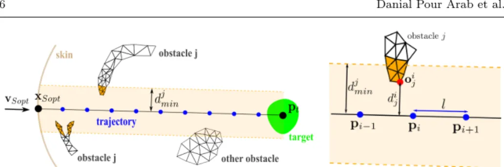
Fig.1). The trajectory is discretized into n−1 steps of length l, where n = (L/l)+1 is the number of points along the trajectory, including the entry and target points. For each organ j considered as an obstacle (in our simulation the ribs and the vessels) first we define the dangerous zone as the volume around the needle bounded by a minimum “safe” distance djmin to this obstacle. This parameter must be set by the surgeon, and can be different for each obstacle independently. For each intermediate point pi of the trajectory, we observe the proximity to
the obstacles during 10s of simulated breathing process. At each iteration of the algorithm, we search for the closest vertex oij in obstacle mesh j at its current
state of the motion. Let us denote dij the perpendicular distance of point oij to
the trajectory (see Fig.1 right). If dij < d j
min, then we consider that point o i j is
within the dangerous zone. It is marked and added to a set of risky points Rij to be
Fig. 1 Left: The initial trajectory (xSopt, vSopt), represented as a homogeneous sequence
of points, between insertion point xSopton the skin and target point ptwithin the targeted
structure (green). Two obstacles are in the vicinity of the trajectory. Obstacle j is made of two parts. The dangerous zone for obstacle j is represented in light orange, and triangles of the meshes of obstacle j that have at least one vertex in the zone are colored in dark orange. Right: An intermediate point piis represented as a blue point. Its distance to the next intermediate
point is l. Point oi
j(red) is the part of obstacle j closest to the trajectory, at a distance of dij.
is accelerated using a KD-tree algorithm [22] so that an iteration of the algorithm is fast and allows for a good coverage of all possible positions of the obstacle.
We could have chosen to select all points within the dangerous zone defined by djmin. However this could have led to a high number of points selected and a high number of calculations. Our objective being real-time computations, this simplified approach allows us to mark only a small subset of points among all the points of obstacle mesh j that are within the dangerous zone, in order to reduce the number of points to monitor later.
During the breathing simulation, the organs move as described in Section 2.2, and the coordinates of all points oij are updated accordingly. The trajectory also
moves with the rest of the anatomy, so that all points pi have moving coordinates,
and the trajectory might not be straight anymore. The initial position of each point, i.e. its position in the preoperative image, is saved and denoted in the rest of the paper respectively oij0, pi0, and pt0 for the target.
The duration of 10 s is enough to cover a few breathing cycles and be repre-sentative of the global movement.The displacement amplitude δptis the maximum
norm of projection vector of−−−→ptpt0 on vSopt. Where pt0 is the initial position of
target point and ptis moving target point recorded during the observation.
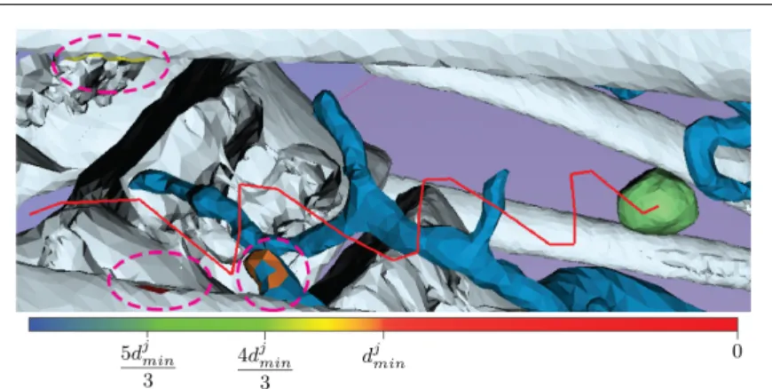
At the end of this phase, that is illustrated on Fig.1, we have a list of points to verify during next phase. For a better visualization, all the triangles that have at least one vertex belonging to Rij will be colored according to the distance between
oij and pi during the next phase. The color will be updated in real-time. (See
Fig.2).
2.3.2 Correction and targeting
In this section we propose an approach that dynamically corrects the initial tra-jectory in an optimal way.
When the risk observation is finished, the simulation of the needle insertion starts at insertion point xSopt and towards the current position of the first pi,
while the breathing simulation is still running. Between each point pi and the
Fig. 2 A trajectory (in red) after correction by method RTIT. Triangles having vertices within Rijare highlighted by pink ovals on the vessels and the ribs. They are colored according to their distance to the trajectory, and their color is updated in real time. The target is in green.
path is clear from any close obstacle, to move the needle forward. If this is not possible, the trajectory is slightly corrected by a calculated displacement vector.
To achieve this, for each obstacle j, at time t of the breathing cycle, and with the needle inserted up to intermediate point pi, if ∃ok ∈ Ri+1j such that, at its
current location, its perpendicular distance to the trajectory do < djmin. During
5s this distance is monitored until either do ≥ djmin (the obstacle is cleared) or
the 5s are over (Fig.3(a)).
The idea is to wait so that point okhas moved away from the neighbourhood
of the path. This waiting strategy is useful to avoid to modify the initial insertion direction. Let us note that even if the direction of insertion is never changed, the final path is not a straight line as the needle is steered within moving anatomical structures, as shown on Fig.2.
If this waiting strategy fails to provide a safe moment, we try to modify the direction of insertion by moving the next point pi+1. For a single point ok ∈
Ri+1j that is inside the dangerous zone which means do < djmin, we calculate a
displacement vector vkas follows :
vk=
−dk∗ di+1
kpi− o0kk
∗ ˆvo
Where vo is the vector rejection of−−−−→pi+1okfrom−−−−→pipi+1, dk= djmin− do, di+1 is
the distance between pi and pi+1, and o0kis the projection of ok on −−−−→pipi+1 (see
Fig.3(a)).
Therefore a displacement vector vi+1is calculated as the average direction of
all displacement vectors. To calculate vi+1for m risky points inside the dangerous
zone detected for pi+1 (as detailed in section 2.3.1), we use :
vi+1=
P
okvk
m (1)
For intermediate points pi+1fairly close to the target point pt, i.e. if kpi+1−
ptk < δpt+ l + (bbd/2) where bbd is the diagonal of tumor’s bounding box, and as
nearby move along with the needle and the target. So the main objective becomes to ensure an accurate targeting. If kpt−pt0k > 0, during 5s this distance is verified
with its new location until we have kpt− pt0k = 0 or this 5s are over. This waiting
strategy is useful for a better realignment of the target.
If waiting is not enough to align the target, then the displacement vector vi+1
for point pi+1is modified to redirect towards the target (see Fig.3(b)), with :
vi+1= pt− pt0 (2)
With the displacement method, the next movement of the needle is made towards an updated p0i+1that is computed by p
0
i+1= pi+1+vi+1. Fig.3 illustrates
this dynamic replanning phase.
(a) general case (b) close to target
Fig. 3 Illustration of the correction step in RTIT method: (a) in the general case, p0i+1is the
modified position of pi+1by vi+1to avoid the obstacle. For a single risky point vi+1= vk
(b) close to the target, pi+1is pt.
3 Real Time Straight Trajectory (RTST)
In order to evaluate our RTIT approach, we propose a simple method called Real Time Straight Trajectory (RTST), which will be used as a reference. This method consists in inserting the needle from insertion point xSoptwith a constant speed s
following the initial direction vSopt until the initial location of ptis reached. This
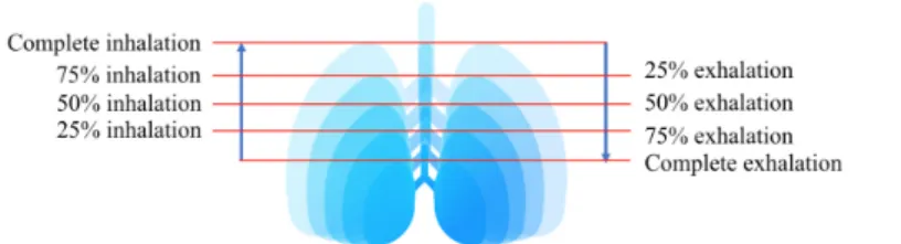
method examines 16 insertion scenarios, that combine eight different starting mo-ments (complete exhalation, 75% exhalation, 50% exhalation, 25% exhalation, 25% inhalation, 50% inhalation, 75% inhalation and complete inhalation. See Fig. 4) with two different speeds (s1 = 2.5mm/s and s2 = 5mm/s). This discretization
of the breathing was chosen empirically as we observed that discretizing more would not significantly change the results. To account for the variability of nee-dle insertion speed between surgeons, we chose these two speeds after consulting experienced surgeons. However, they would rather fit a simple scenario of robotic constant insertion.
In the next section, we define the different evaluation criteria for choosing the best scenario among these sixteen. Then we compare it to the result obtained from the RTIT approach.
Fig. 4 Illustration of the 8 starting moments for the needle insertion
4 Evaluation criteria
The objective is to find the best combination start/speed given by RTST, and then compare the trajectory produced with this combination to the path produced using RTIT. In this section, we detail the two criteria we used to choose the best combination: target positioning error (TPE), and distance of the actual path to risky structures. We also detail how we compute the deviation from the initial path, that is used as another criterion to compare with RTIT.
The TPE is defined as the distance between the final position pf of the needle
tip at the end of the insertion and pt:
TPE = kpf− ptk (3)
The distance of the actual path to risky structures and the deviation from the initial path are measured during the insertion simulation. At each time step of the simulation, the minimal distance between the needle tip and the obstacles is measured. At the end of the simulation, the distance of the actual path to risky structures is the minimum of the measured distances. This criterion helps us to evaluate the trajectory’s safety. Among the paths produced with the 16 scenarios, we first look for the one(s) with the best accuracy i.e the path(s) that has minimum TPE calculated with equation 3. If several paths have a similar accuracy, the path that has the greatest minimum distance to obstacles is selected to be compared with RTIR’s result.
At each time step, in RTIT approach, for point pi+1we also measure the norm
of its displacement vector vi+1 if there is any displacement computed with Eq. 1
and 2. This allows us to measure the maximal and average displacements that had to be performed, to quantify the degree of correction of method RTIT.
4.1 Experimental setup and input data
In order to validate our approach, an experiment was conducted on six 3D models of abdominal structures from the 3D-IRCADb database [23]. This database in-cludes several sets of segmented medical images of patients. For all patients, the anatomical structures reconstructed as 3D triangular surface meshes are provided, among which the liver, the lungs, the ribs and spine, the vascular structure, the skin, and one or several tumors. For this study, we chose a subset of six datasets from three male and three female patients with liver tumors.
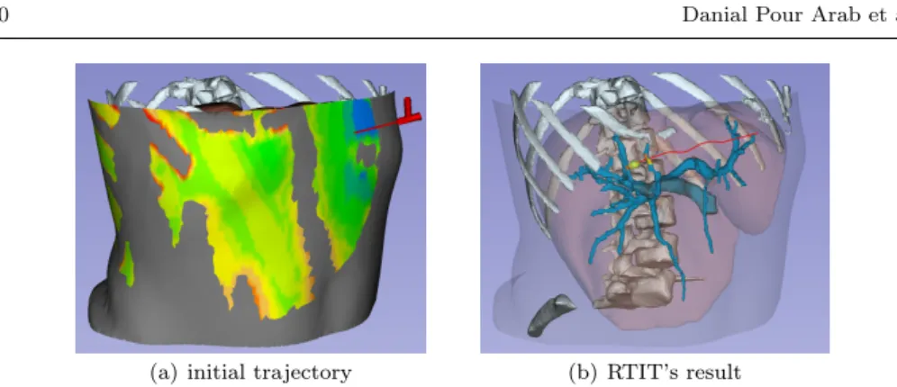
(a) initial trajectory (b) RTIT’s result
Fig. 5 (a) initial trajectory. (b) RTIT’s result after getting to the target (red). For a good visualization, some models are omitted and the liver and skin models are represented as semi-transparent.
For each patient model, a straight trajectory in static environment was com-puted by the algorithm proposed by Hamz´e et al. [15] (See Fig. 5(a)). Then the breathing simulation was activated with T = (−0.1, 0.1, −0.1).
Lin [24] proposed 5 to 10mm safe distance from vessels, therefore we set dmin = 7mm for vessels. For ribs we set dmin = 5mm after consulting
experi-enced surgeons. Length of each step (described in Section 2.3.1) typically varies from 5 to 20mm apart [25], accordingly we set l = 5mm.
Given an initial trajectory, our dynamic path planning methods were started. The RTIT’s result is illustrated in Fig. 5(b).
5 Results and discussion
Table 1 shows the TPE for the six patient models and both methods. The re-ported average TPE were respectively 0mm for RTIT and 0.725mm for the path provided by the scenario chosen as best for RTST. According to this result our RTIT approach has a significantly better targeting accuracy than RTST, showing its capacity to adapt the path to the motion of the anatomy.
Note that this result has been obtained with a breathing simulation, where recognition and tracking errors that happen during clinical applications are not taken into account.
During such an intervention, targeting accuracy is essential to realize a com-plete destruction of the tumor. To achieve this, at least 5mm ablative margin in all surrounding directions of the tumor is required [7]. Moreover the damages to the healthy tissues should remain minimal. Therefore a lower TPE means a lower risk of recurrence and minimal damage to the healthy tissues.
Table 1 TPE (in mm) for the six cases and both methods RTIT and RTST. Case # 1 2 3 4 5 6 AVG STD
RTIT 0 0 0 0 0 0 0 0
To confirm that our method RTIT decreased the risk of collision comparing to the simple RTST method, for both obstacles (ribs and vessels) and all cases we counted all points of sets Rij that remained inside the dangerous zone despite the
attempts of avoiding the obstacles. This number of points is displayed in Table 2, along with the distance of the dynamic path to risky structures for both methods RTIT and RTST. In cases #2 and #6 both methods were capable to keep a safe distance to the obstacles above dmin. In cases #3, #4 and #5, both methods
were under the threshold of dmin for the vessels. However, RTIT always found
paths above 5.78mm in average, and in 3 cases (#1, #2 and #3) it found as safe path, whereas RTST always found paths below 5.86mm in average, and in case #5 minimum distance to vessels was 2.99mm. Both methods were able to avoid the ribs, therefore in Table 2 we just summarize the distances to vessels. Overall, our RTIT shows a significant improvement to avoid the collisions compared to RTST method. This is mainly due to its path correction algorithm.
Table 2 Number of points of Ri
jthat remained below the minimal distance to the generated
dynamic path, with their minimal and average distances to the path (in mm).
Case # 1 2 3 4 5 6 RTIT # of points 0 0 5 2 1 0 Min dist - - 4.21 6.74 5.78 -AVG dist - - 5.78 6.79 5.78 -STD - - 0.95 0.07 - -RTST # of points 3 0 8 4 5 0 Min dist 4.64 - 4.34 4.35 2.99 -AVG dist 5.86 - 5.23 5.41 4.76 -STD 1.05 - 0.76 0.9 1.68
-We also summarize the maximum and average deviations from the initial path for the RTIT method in Table 3. We can observe that no deviation above 2.89mm was necessary, which remains within the range of what is physically reproducible during an intervention.
Table 3 Deviations from the initial path for the RTIT method (in mm). Case # 1 2 3 4 5 6
Max 0 0 1.66 0 2.89 0 AVG 0 0 1.62 0 2.89 0 STD - - 0.056 0 -
-In our experimental data an obstacle mesh could contain [9000,110000] points. Processing all these points takes 790 ± 223 ms. Our selection approach allows us to process only [0,3] points per intermediate point pi, reducing the process to
0.062 ± 0.022 ms.
Finally, let us note that during the breathing simulation, the points pithat the
needle has already reached follow the movement of the anatomy, to reproduce the natural insertion of the needle in the body. This is done by applying to points pi
This allows to bring more realism in this simulation. In a real environment, where the intervention is monitored in real time for instance under ultrasound guidance, the needle would have to be detected as well as the organs motions.
6 Conclusion
This study is a first step towards intelligent robotic insertion under real-time image guidance. It proposes real-time path replanning for percutaneous procedures in the abdomen during free breathing. We presented an intelligent dynamic planning approach, based on an observation of the critical structures, and an iterative wait-or-correct algorithm that anticipated the motions to keep the trajectory at a safe distance from critical structures. Our approaches provides safer and better targeted results than the na¨ıve RTST method that examines sixteen scenarios of needle insertions, while requiring minimal deviations from the initial trajectory.
This work was focused on the dynamic replanning algorithm. The algorithm was tested on six real patient cases, but with a synthetic breathing simulation. In future works, this simplified environment needs to be replaced with real-time tracking, and methods able to detect dynamically the progression of the needle during the insertion and the location and motion of the surrounding critical organs. Compliance with ethical standards
Funding: This work was partially supported by collaborative grant ECHOPT from the in-terventional imaging workpackage of the France Life Imaging (FLI) network.
Conflict of interest: The authors declare that they have no conflict of interest.
Protection of human and animal rights statement: All 3D models are retrospective and were anonymized before delivery to the researchers.
Informed consent: Informed consent was obtained from all individual participants included in the study.
References
1. Liang, P., Wang, Y.: Microwave ablation of hepatocellular carcinoma. Oncology 72(Suppl. 1), 124–131 (2007)
2. Maybody, M., Solomon, S.B.: Image-guided percutaneous cryoablation of renal tumors. Techniques in vascular and interventional radiology 10(2), 140–148 (2007)
3. Georgiades, C.S., Hong, K., Bizzell, C., Geschwind, J.F., Rodriguez, R.: Safety and efficacy of CT-guided percutaneous cryoablation for renal cell carcinoma. Journal of Vascular and Interventional Radiology 19(9), 1302–1310 (2008)
4. Maeda, M., Saeki, I., Sakaida, I., Aikata, H., Araki, Y., Ogawa, C., Kariyama, K., Nouso, K., Kitamoto, M., Kobashi, H., Sato, S., Shibata, H., Joko, K., Takaki, S., Takabatake, H., Tsutsui, A., Takaguchi, K., Tomonari, T., Nakamura, S., Nagahara, T., Hiraoka, A., Matono, T., Koda, M., Mandai, M., Mannami, T., Mitsuda, A., Moriya, T., Yabushita, K., Tani, J., Yagi, T., Yamasaki, T.: Complications after radiofrequency ablation for hepa-tocellular carcinoma: A multicenter study involving 9,411 japanese patients. Liver Cancer 9(1), 50–62 (2020)
5. Bale, R., Schullian, P., Eberle, G., Putzer, D., Zoller, H., Schneeberger, S., Manzl, C., Moser, P., Oberhuber, G.: Stereotactic radiofrequency ablation of hepatocellular carci-noma: a histopathological study in explanted livers. Hepatology 70(3), 840–850 (2019)
6. Engstrand, J., Toporek, G., Harbut, P., Jonas, E., Nilsson, H., Freedman, J.: Stereotactic CT-guided percutaneous microwave ablation of liver tumors with the use of high-frequency jet ventilation: An accuracy and procedural safety study. American Journal of Roentgenol-ogy 208(1), 193–200 (2017)
7. Mulier, S., Ni, Y., Jamart, J., Ruers, T., Marchal, G., Michel, L.: Local recurrence after hepatic radiofrequency coagulation: Multivariate meta-analysis and review of contributing factors. Annals of surgery 242(2), 158 (2005)
8. Baegert, C., Villard, C., Schreck, P., Soler, L.: Multi-criteria trajectory planning for hepatic radiofrequency ablation. In: proceedings of MICCAI’07, Springer LNCS, vol. 4791, pp. 584–592 (2007)
9. Baegert, C., Villard, C., Schreck, P., Soler, L., Gangi, A.: Trajectory optimization for the planning of percutaneous radiofrequency ablation of hepatic tumors. Computer Aided Surgery 12(2), 82–90 (2007)
10. Seitel, A., Engel, M., Sommer, C., Redeleff, B., Essert-Villard, C., Baegert, C., Fangerau, M., Fritzsche, K., Yung, K., Meinzer, H.P., Maier-Hein, L.: Computer-assisted trajectory planning for percutaneous needle insertions. Medical Physics 38(6), 3246–3260 (2011) 11. Schumann, C., Bieberstein, J., Trumm, C., Schmidt, D., Bruners, P., Niethammer, M.,
Hoffmann, R., Mahnken, A., Pereira, P., Peitgen, H.: Fast automatic path proposal com-putation for hepatic needle placement. In: SPIE Medical Imaging, vol. 7625, p. 76251J (2010)
12. M¨arz, K., Franz, A.M., Stieltjes, B., Iszatt, J., Seitel, A., Radeleff, B., Meinzer, H.P., Maier-Hein, L.: Mobile EM field generator for ultrasound guided navigated needle insertions. In: Proceedings of the 4th International Conference on Information Processing in Computer-Assisted Interventions, IPCAI’13, pp. 71–80 (2013)
13. Stoll, M., Boettger, M., Schulze, C., Hastenteufel, M.: Transfer of methods from radiother-apy planning to ablation planning with focus on uncertainties and robustness. Biomedical Engineering / Biomedizinische Technik. 57(SI-1 Track-C), 901–904 (2012)
14. Villard, C., Soler, L., Papier, N., Agnus, V., Gangi, A., Mutter, D., Marescaux, J.: RF-Sim: a treatment planning tool for radiofrequency ablation of hepatic tumors. In: proceedings of Information Visualization, pp. 561–566. IEEE Computer Society Press (2003) 15. Hamz´e, N., Peterl´ık, I., Cotin, S., Essert, C.: Preoperative trajectory planning for
per-cutaneous procedures in deformable environments. Computerized Medical Imaging and Graphics 47, 16–28 (2016)
16. Li, P., Jiang, S., Liang, D., Yang, Z., Yu, Y., Wang, W.: Modeling of path planning and needle steering with path tracking in anatomical soft tissues for minimally invasive surgery. Medical engineering & physics 41, 35–45 (2017)
17. Shahriari, N., Georgiadis, J.R., Oudkerk, M., Misra, S.: Hybrid control algorithm for flex-ible needle steering: Demonstration in phantom and human cadaver. PloS one 13(12), e0210052 (2018)
18. Vrooijink, G.J., Abayazid, M., Patil, S., Alterovitz, R., Misra, S.: Needle path planning and steering in a three-dimensional non-static environment using two-dimensional ultrasound images. The International journal of robotics research 33(10), 1361–1374 (2014) 19. Patil, S., Alterovitz, R.: Interactive motion planning for steerable needles in 3D
environ-ments with obstacles. In: 2010 3rd IEEE RAS & EMBS International Conference on Biomedical Robotics and Biomechatronics, pp. 893–899. IEEE (2010)
20. Bernardes, M., Adorno, B.V., Poignet, P., Borges, G.: Robot-assisted automatic inser-tion of steerable needles with closed-loop imaging feedback and intraoperative trajectory replanning. Mechatronics 23(6), 630–645 (2013)
21. Lapouge, G., Troccaz, J., Poignet, P.: Multi-rate unscented kalman filtering for pose and curvature estimation in 3D ultrasound-guided needle steering. Control Engineering Prac-tice 80, 116 – 124 (2018). DOI https://doi.org/10.1016/j.conengprac.2018.08.014. URL http://www.sciencedirect.com/science/article/pii/S0967066118304416
22. Zhou, K., Hou, Q., Wang, R., Guo, B.: Real-time KD-tree construction on graphics hard-ware. ACM Transactions on Graphics (TOG) 27(5), 1–11 (2008)
23. 3D-IRCADb (3D Image Reconstruction for Comparison of Algorithms Database), accessed 2019. URL http://www.ircad.fr/research/3dircadb/
24. Lin, S.M.: Recent advances in radiofrequency ablation in the treatment of hepatocellular carcinoma and metastatic liver cancers. Chang Gung Med J 32(1), 22–32 (2009) 25. Cannon, R., Ellis, S., Hayes, D., Narayanan, G., Martin, R.C.: Safety and early efficacy of
irreversible electroporation for hepatic tumors in proximity to vital structures. Journal of surgical oncology 107(5), 544–549 (2013)