HAL Id: hal-01921463
https://hal.sorbonne-universite.fr/hal-01921463
Submitted on 13 Nov 2018
HAL is a multi-disciplinary open access
archive for the deposit and dissemination of
sci-entific research documents, whether they are
pub-lished or not. The documents may come from
teaching and research institutions in France or
abroad, or from public or private research centers.
L’archive ouverte pluridisciplinaire HAL, est
destinée au dépôt et à la diffusion de documents
scientifiques de niveau recherche, publiés ou non,
émanant des établissements d’enseignement et de
recherche français ou étrangers, des laboratoires
publics ou privés.
pressure
F. Decremps, M. Fischer, A. Polian, J. Itié
To cite this version:
F. Decremps, M. Fischer, A. Polian, J. Itié. Ionic layered PbFCl-type compounds under high pressure.
Physical Review B: Condensed Matter and Materials Physics (1998-2015), American Physical Society,
1999, 59 (6), pp.4011 - 4022. �10.1103/PhysRevB.59.4011�. �hal-01921463�
Ionic layered PbFCl-type compounds under high pressure
F. Decremps,* M. Fischer, A. Polian, and J. P. Itie´
Physique des Milieux Condense´s, Universite´ Pierre et Marie Curie, B 77, 75252 Paris Cedex 05, France
M. Sieskind
CNRS, laboratoire PHASE, Boˆıte Postale 20, 67037 Strasbourg Cedex 2, France
X- ray diffraction experiments under high pressure have been carried out on BaFCl, BaFBr, and BaFI that belong to the family of layered ionic crystals with the matlockite PbFCl structure. Experiments up to 30 GPa with different pressure transmitting media and different powder proportions were undertaken to determine the anisotropic stress component contribution. The bulk and linear moduli were determined for each compound and structural phase transitions have been observed near 21 and 27 GPa for BaFCl and BaFBr, respectively. The difference in bond strength due to the layered properties of these compounds results in clear differences in compressibilities along the two principal directions, perpendicular and parallel to the C4 axis of the tetragonal
matlockite structure. The anisotropic behavior of the unit-cell parameters observed under compression is attributed to the anisotropic coordination of the highly polarizable halogen anion. This phenomenon created a large static dipole at the halogen and involves an energy contribution that seems to stabilize the layered structure. [S0163-1829(99)03206-3]
I. INTRODUCTION
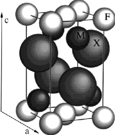
The alkaline-earth fluorohalides M FX, where M =Ca, Sr, Ba, Pb, or Eu and X=Cl, Br, or I, form an important class of materials crystallizing in the PbFCl-type tetragonal structure
P4/nmm (Fig. 1 and Table I), also called the matlockite
structure.6 When doped with rare-earth ions, these crystals possess the property of photostimulated luminescence. Therefore, they are used for technological applications like x-ray image plates detectors7 (for example, BaFBr:Eu2+) or as in situ pressure gauge for experiments with diamond anvil cells at high temperature.8,9
Some previous studies10–12 on several M FX compounds have shown that these crystals exhibit anisotropic properties, a direct consequence of their macroscopic layered character.13 Moreover, like PbI2 or CdX2 crystals, these lay- ered compounds are formed by atoms bonded by ionic-type forces, which seems to a priori be incompatible with the formation of a layerlike crystal. In conventional covalent lay- ered materials, all the bonding electrons are within the sheets so that the layers are bonded by van der Waals forces. The issue to be investigated here is physical origin that leads to the formation of ionic-layered substances.
The matlockite family M FX forms an interesting group of compounds exhibiting an anisotropic bonding scheme that depends, at ambient conditions, on the chemical nature of the
M and X atoms. They are therefore well suited to probe the
physical interatomic properties that stabilize ionic-layered structure. In the present study, a high-pressure investigation of x-ray diffraction was made on BaFX (X=Cl, Br, and I) up to 30 GPa. Moreover, to understand how the pressure affects the intrinsic anisotropic behavior of these compounds, differ- ent high-pressure experiments on the same crystal with vari- ous pressure transmitting media (and various sample powder/ pressure transmitting medium proportion) were carried out in
order to provide some insight on the deviatoric stresses or grain-grain effects.
The principal objectives of this study were
(1) to determine the pressure response of the layered
M FX crystals and to compare these results with those ob-
tained when an atom species is replaced by another one, (2) to discuss and analyze our experimental data in terms of crystal compressibilities (taking into account the deviatoric stress effects) and to compare these data with previous ex- perimental and theoretical studies on BaFCl, BaFBr, and BaFI, and (3) to determine the nature of the bonding that stabilizes the layered structure of ionic compounds.
II. EXPERIMENTAL PROCEDURE
Starting from high-purity materials, single crystals of
M FX were grown14 by slowly cooling a molten mixture of
FIG. 1. An example of the matlockite tetragonal structure
→
TABLE I. Crystal data for selected matlockite-type compounds. a and c are the lattice constants in Å, u (halogen), and u' (metal) are lattice parameters, and dAB is the distance between ion A and B.
BaFCl BaFBr BaFI SrFCl SrFBr PbFCl PbFBr PbFI (Ref. 1) (Ref. 1) (Ref. 1) (Ref. 2) (Ref. 3) (Ref. 4) (Ref. 5) (Ref. 5)
a (Å) 4.394 4.508 4.654 4.126 4.218 4.110 4.18 4.23 c (Å) 7.225 7.441 7.962 6.958 7.337 7.246 7.59 8.77 u 0.6472 0.6497 0.6522 0.6489 0.6479 0.6497 0.65 0.65 u' 0.2049 0.1911 0.1704 0.2015 0.1859 0.2058 0.195 0.167 dFF (Å) 3.106 3.187 3.290 2.917 2.982 2.906 3.18 3.36 d MF (Å) 2.649 2.665 2.693 2.494 2.511 2.539 2.56 2.58
carefully dehydrated MX2 and M F2 following the chemical reaction MX2+M F2 2 M FX. Because of their lamellar character, water is easily absorbed between the layers mak- ing them opaque. The crystals were therefore stored in a dessiccator and carefully selected to be fully transparent.
These studies were performed using a conventionnal dia- mond anvil cell driven by a membrane15 with diamond anvil culets of 500 µm in diameter. The stainless-steel gaskets were preindented to a thickness of 50 µm and drilled to a diameter of 150 µm. Fine powder of sample was loaded into the gasket hole. At pressures above 11 GPa (at room tem- perature), all pressure-transmitting media are solid and intro- duce anisotropic stress components that could mask the in- trinsic crystal anisotropy. Therefore, in order to determine the deviatoric stress contributions, we used two different
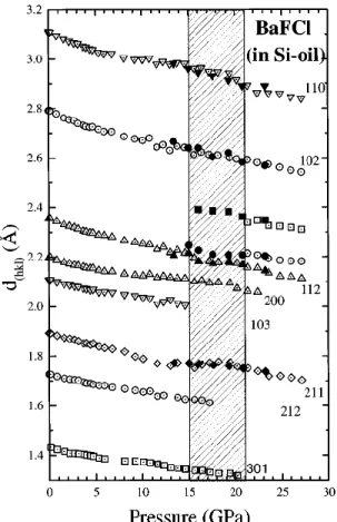
FIG. 2. Lattice spacings dhkl as a function of pressure for BaFCl
in silicone oil. At about 21 GPa, a phase transition takes place. Open (full) symbol: upstroke (downstroke) experimental data.
pressure-transmitting media (silicone oil and argon) and vari- ous powder ratios during the investigation of the BaFX struc- ture behavior. To measure the in situ pressure, the fluores- cence emission of a ruby chip16 placed into the gasket hole was systematically recorded before and after each x-ray- diffraction experiment.
The high-pressure powder x-ray-diffraction measurements were made in the energy dispersive mode with the wiggler at the DW11 station of the DCI storage ring of the LURE (Or- say, France). After energy calibration of the detector, the 20 angle was determined by collecting diffraction patterns of a copper sample placed between the diamonds. The polychro- matic x-ray beam was collimated to a 50X50-µm2 spot cen- tered on the gasket hole. Because of the high scattering power of M FX compounds, exposure times between 20 and
FIG. 3. Lattice spacings dhkl as a function of pressure for BaFBr
IONIC LAYERED PbFCl-TYPE COMPOUNDS UNDER... 4013
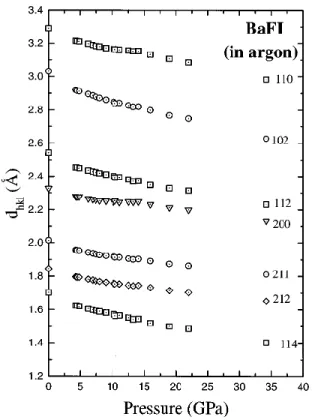
FIG. 4. Lattice spacings dhkl as a function of pressure for BaFI
in argon.
30 mn were sufficient to collect diffraction patterns with suit- able peak-to-background intensity ratios.
III. RESULTS
A. Lattice parameters and cell volume
The unit-cell parameters a and c of the tetragonal matloc- kite compounds and the volume V=a2c were calculated,
with a least-squares refinement program DICVOL,17 from the diffraction patterns. Peak positions were determined by a Gaussian fitting of the diffracted lines. For the complete set of compounds, at least seven intense diffracted lines were selected up to the maximum pressure achieved and used in the refinement (see Figs. 2–4 for BaFCl, BaFBr, and BaFI, respectively).
Variations, sometimes large, of the diffraction linewidths were observed in different runs with two different pressure- transmitting media (silicone oil and argon), even with ap- proximatively the same small powder quantity in order to minimize the grain-grain contact effects. The effects on the compression curves due to the deviatoric stresses are dis- cussed in Appendix A.
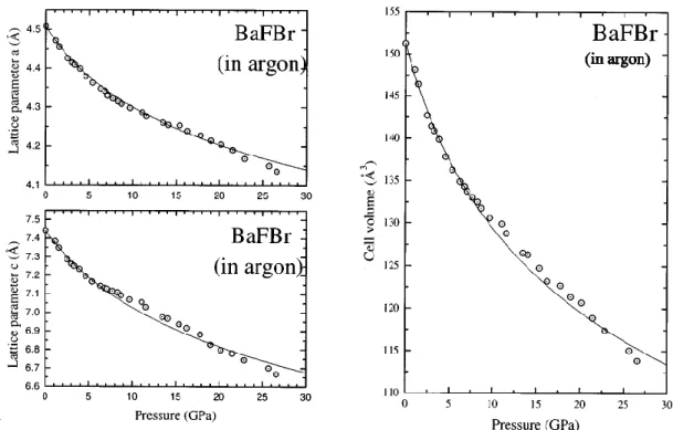
Finally, the accurate values of the unit-cell parameters a,
c, and cell volume V of BaFCl, BaFBr, and BaFI are given as
a function of pressure in Figs. 5–7 respectively.
For the three crystals studied, the normalized volume
V/V0 , where V0 is the cell volume at ambient conditions, is plotted as a function of the pressure in Fig. 8.
B. Phase transition
At 21 GPa for BaFCl and 27 GPa for BaFBr, the appear- ance of new diffraction peaks reflects the occurrence of a phase transition, in good agreement with the previous high- pressure study made by Shen et al.10 or Subramanian et al.18 These transitions are confirmed by Raman scattering ob- tained on single crystals of BaFCl, BaFBr, and BaFI using nitrogen as the pressure-transmitting medium,19 where the phase transitions were observed at 21, 27, and 55 GPa, re- spectively. Unfortunately, in the best cases, only two new lines corresponding to the d spacing of the new structure were available and the high-pressure structure could not be identified without ambiguities. Results recently published by Subramanian et al.18 allowed us to analyze our spectra above the transition pressure, with the assumption that all the peaks
FIG. 5. Room-temperature axial and volumic compressions for BaFCl as a function of pressure. The solid curves represent the Mur- naghan equation of state best fit.
FIG. 6. Room-temperature axial and volumic compressions for BaFBr as a function of pressure. The solid curves represent the Mur- naghan equation of state best fit.
come from the high-pressure phase. Our data agree with sev- eral monoclinic structures including the P21 /m one pro- posed in this paper. However, we cannot exclude a possible phase mixture above 21 GPa for BaFCl or 27 GPa for BaFBr, suggesting large kinetics effects for the phase change at ambient temperature.
Three different experiments were made on BaFBr up to about 30 GPa with different quantities of powder and
pressure-transmitting media. Because we observed the phase transition at 27 GPa in the three runs, we conclude that it is not affected by the deviatoric stresses. On the other hand, the intensity and the width of the new diffraction peaks (ob- served above 27 GPa) depend on the pressure-transmitting medium and the changes in diffraction patterns were more pronounced in silicone oil than in argon. The experiment on BaFCl in argon were only performed up to 20.2 GPa and
FIG. 7. Room-temperature axial and volumic compressions for BaFI as a function of pressure. The solid curves represent the Murnaghan equation of state best fit.
IONIC LAYERED PbFCl-TYPE COMPOUNDS UNDER... 4015
B
(
a
c
FIG. 8. Variation of the relative volume of BaFX (X=Cl, Br, and I) as a function of pressure. Notice the small difference of the compression curve for the three different compounds with different degrees of layering.
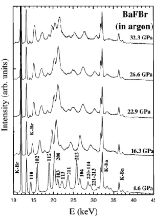
FIG. 10. Energy dispersive x-ray-diffraction spectra for BaFBr in argon at different pressures above and below the phase transition one. esc, K-Ba, and K-Br refer to the escape peaks and the fluo- rescence lines of Ba and Br, respectively. The value of the Bragg angle was 8.0375°.
therefore the phase transition in this compound is illustrated in Fig. 9 by the evolution (up to 22.5 GPa) of the diffraction spectra when silicone oil was used. Figure 10 for BaFBr in argon shows these changes up to 32.3 GPa and Table II gives the values of the new diffraction peaks position for the com- plete set of experiments.
C. Bulk and linear moduli
The isothermal volume data determined above are fitted with a Murnaghan equation of state:20
V B'
= 1+
0 0
-1/B'
P , (1)
where V0 is the cell volume at ambient conditions, B0 the bulk modulus, and B' its pressure derivative.
The pressure–lattice-parameters data, a( P) and c( P), were fitted with a similar equation of state:21
FIG. 9. Energy dispersive x-ray-diffraction spectra for BaFCl in
a = 0 c = 0 B'a 1+ a B'c 1+ c -1/B'a P -1/Bc' P , (2) , (3)
silicon oil at different pressures above and below the phase transi- tion one. esc and K-Ba refer to the escape peaks and the fluores- cence lines of Ba, respectively. The value of the Bragg angle was 7.474°.
where a0 and c0 are the room-pressure lattice parameters, Ba
and Bc the linear moduli along the direction perpendicular
and parallel to the tetragonal axis, respectively, and B'a and
B'c their pressure derivatives.
B B V
(
(
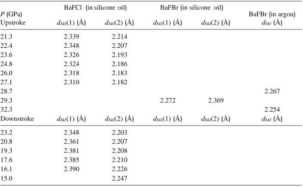
TABLE II. Interplanar distances dhkl (in Å) corresponding to the new diffraction peaks of the high-
pressure phase of BaFCl and BaFBr. For experiments with silicone oil as pressure-transmitting media, two new peaks [dhkl(1) and dhkl(2)] have been followed. P represent the pressure in GPa.
BaFCl (in silicone oil) BaFBr (in silicone oil)
From the experimental data obtained by using argon as a pressure-transmitting medium, the value of these parameters deduced for each compound are listed in Table III and the result of the best fit is plotted in Figs. 5–7.
1. BaFCl
A previous ultrasonic study of the elasticity of BaFCl single crystals under hydrostatic pressure22 yielded to B0
=44±5 GPa and B'=5.8±0.7, in excellent agreement with the present x-ray-diffraction results: B0=45±3 GPa and
B'=5.2±0.5. These results are also consistent with shell
model calculations12 B0=41.4 GPa or scaling factors:24 B0 =43.0 GPa, and in a slight agreement with LDA (local den- sity approximation) calculations:23 B0=51.6 GPa. On the other hand, our results differ significantly from those ob- tained by energy dispersive x-ray-diffraction experiments
TABLE III. Equation-of-state parameters of BaFX (X=Cl, Br, I). The calculated errors on these parameters include both volume and pressure-measurement uncertainties. ti P corresponds to the pressure range used to determine each parameter.
Compounds Authors ti P (GPa) Ba(GPa) B'a Bc(GPa) B'c B0 (GPa) B'
This worka 21 132±12 18±5 139±15 10±4 45±3 5.2±0.5
BaFCl
Shena et al. (Ref. 10)
Decrempsb et al. (Ref. 11)
Balasubramanianb et al. (Ref. 12)
21 155±10 133±13 105 17±4 237±12 131±22 195 0±1 62±6 44±5 41.4 4±1 5.8±0.7 Kalpanad et al. (Ref. 23) 51.6 4
Sieskinde et al. (Ref. 24) 131 124 43
This worka 7 135±20 19±8 109±20 15±8 42±6 6±2
BaFBr
Shena et al. (Ref. 10)
Decrempsb et al. (Ref. 11)
Kalpanad et al. (Ref. 23)
27 156±14 134±30 15±4 121±28 108±18 9±2 44±7 41±10 44.0 5±1 4 Sieskinde et al. (Ref. 24) 118 111 38.5
BaFI
This worka
Kalpanad et al. (Ref. 23)
34 150±20 22±6 70±10 11±5 36±5 41.2
6±1 4 Sieskinde et al. (Ref. 24) 100 94.5 32.8 aEnergy dispersive x-ray-diffraction experiments on powder.
bUltrasonic and/or Brillouin scattering experiments. cShell-model calculations.
dCalculations by the tight-binding linear muffin-tin-orbital method within the local-density approximation. eScaling factors (deduced from the shell-model formulas and from the physical properties of the fluoride M F
2).
P (GPa)
Upstroke dhkl(1) (Å) dhkl(2) (Å) dhkl(1) (Å) dhkl(2) (Å)
BaFBr (in argon)
dhkl(Å) 21.3 2.339 2.214 22.4 2.348 2.207 23.6 2.326 2.193 24.8 2.324 2.186 26.0 2.318 2.183 27.1 2.310 2.182 28.7 2.267 29.3 2.272 2.369 32.3 2.254 Downstroke dhkl(1) (Å) dhkl(2) (Å) dhkl(1) (Å) dhkl(2) (Å) dhkl(Å) 23.2 2.348 2.203 20.8 2.361 2.207 19.3 2.381 2.208 17.6 2.385 2.210 16.1 2.390 2.226 15.0 2.247
IONIC LAYERED PbFCl-TYPE COMPOUNDS UNDER... 4017
(
(
(
TABLE IV. Comparison between the effect of the relative vol- ume V/V0 and the X anion chemical nature on the c/a ratio.
c/a 1.715 1.655 1.645 BaFCl BaFBr V/V0 V/V0 1 1 0.93 BaFI V/V0 1 0.86 0.85
performed by Shen et al.10 using ethanol:methanol:water (16:3:1) as a pressure-transmitting medium: B0=62 ±6 GPa and B'=4±1, where the difference on the bulk modulus is larger than 30%. More specifically, the compari- son between the lattice-parameter variation c( P) (linear modulus Bc=237±12 GPa) of Shen et al.10 and our experi-
mental data (Bc=139±15 GPa, obtained using argon)
clearly reveal the effect of deviatoric stresses and/or grain- grain contact that may have strongly affected the accuracy of their results.
2. BaFBr
A first-order Murnaghan equation of state was fitted to our results up to 27 GPa (phase-transition pressure), although deviatoric stresses seem to have an effect above 7 GPa (weak shrinking of the gasket hole). Contrary to BaFCl, the present results on BaFBr (B0=42±6 GPa and B'=6±2) are con- sistent with the values of Shen et al.:10 B0=44±7 GPa and
B'=5±1. Moreover, a combined Brillouin scattering/
ultrasonic study carried out in parallel with this work11 led to
B0=42.5±5.0 GPa. Good agreement is also obtained with
the moduli given by the theory: Kalpana et al.23 (LDA method) published B0=44.0 GPa and Sieskind et al.24 (scal- ing factor) B0=38.5 GPa.
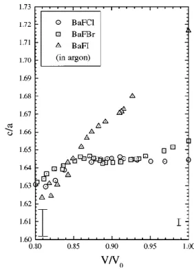
FIG. 11. Change in the ratio c/a of BaFCl (circles), BaFBr (squares), and BaFI (up triangles) with relative cell volume V/V0 ,
where V0 denotes the volume at atmospheric pressure and at room
temperature. The corresponding experiments were carried out with a small powder quantity and argon as a pressure-transmitting me- dium. The linear variation of the uncertainties on the ratio and the relative cell volume are given by the errors bars.
D. Layer character under pressure
We have also used Eqs. (2) and (3) to calculate the linear moduli and their pressure derivatives perpendicular and par- allel to the tetragonal axis (see Table III). The following inequalities demonstrate that the ratio of the linear moduli
Bc /Ba decreases with increasing X anion volume:
3. BaFI
Because of the layered nature of this crystal, we paid special attention to the experimental procedure (two samples were run instead of one as with the other two materials). The
Bc Ba BaFCl =1.0> Bc =0.80> a BaFBr Bc =0.45. a BaFI (4) values of B0=36±5 GPa and B'=6±1 were determined by
fitting a Murnaghan equation of state to the data points up to 34 GPa. No signature of a phase transition has been observed up to 34 GPa, in good agreement with the high-pressure Brillouin and Raman-scattering experiments previously performed19 (pressure transition seen at about 55 GPa). The comparison with theoretical results obtained by Kalpana
et al.23 (B0=41.2 GPa and B'=4) or Sieskind et al.24 (B0 =32.8 GPa) is good.
The uncertainty in the ratios is less than 5%. For BaFBr, because of the anomalies detected above 7 GPa, the linear moduli were determined by fitting the Murnaghan equation only between 0 and 7 GPa. As already mentioned, apart from BaFCl, these results are consistent with previous results ob- tained by x-ray-diffraction10 and ultrasonic or Brillouin- scattering techniques.11,22,25,26 On the other hand, our experi- mental results differ considerably from those calculated by Sieskind et al.,24 who report a ratio of the linear moduli
TABLE V. Selected distances, in Å, between ions in some matlockite-type compounds at ambient pres- sure.
BaFCl BaFBr BaFI SrFCl SrFBr PbFCl PbFBr PbFI (Ref. 1) (Ref. 1) (Ref. 1) (Ref. 2) (Ref. 3) (Ref. 4) (Ref. 5) (Ref. 5)
d M'X (Å) 3.282 3.403 3.582 3.104 3.221 3.089 3.18 3.36
d M"X (Å) 3.194 3.409 3.844 3.110 3.387 3.216 3.45 4.30
FIG. 12. Polyhedral representation of the matlockite structure. Contrary to the fluorine inside the M 4F tetrahedra, the halogen X is
in a nonequidistant position from the M cations that defined the pyramid corner (d M'X-=d M"X). (a and c are the crystallographic
axes.)
Bc /Ba that does not change with the chemical nature of the
ions, with a value of 0.94 for all these crystals. In fact, Sie- skind discussed this result as an instructive example of the restrictive applicability of the scaling factor, where the crys- tals M FX are considered as quasitridimensional compounds at ambient conditions.
As shown in Appendix A, the effects of the deviatoric stresses on the pressure dependence of the c/a ratio are small when argon is used as a pressure-transmitting medium. Therefore, the pressure response of the c/a ratios (illustrated in Fig. 11) describes the evolution of the intrinsic anisotropic bonding of these compounds.27 The evolution of c/a for the three compounds contrasts with the V/V0( P) curves (see Fig. 8) that are the same whatever the crystal, and therefore whatever their layer character. For BaFI, the c/a ratio strongly decreases down to V/V0=0.85 (corresponding to a
TABLE VI. Computed energy polarization of BaFX crystals. Crystals BaFCl BaFBr BaFI
Epol (kJ mol-1) 6.1 7.4 22.0
pressure of 15 GPa). A similar type of variation is observed for BaFBr where the layered/nonlayered transition is seen at
V/V0=0.93 ( P~3 GPa). Below this value, the c/a ratio
seems to be constant, revealing a strengthening of the initial weak forces along the C4 axis. On the other hand, the BaFCl
c/a ratio does not exhibit a strong pressure dependence
down to V/V0=0.85, which is consistent with its tridimen- sional character.
Below V/V0=0.85, all the three compounds appear to show a low decrease in c/a. However, because of the experi- mental error at high pressure (see error bar in Fig. 11), it is not possible to draw any reliable conclusions.
IV. COHESIVE ENERGY OF IONIC COMPOUNDS WITH LAYERED STRUCTURE
A. Polarization energy and structure stability
Table IV contains the values of the c/a ratios of BaFX as a function of the relative volume V/V0 . From this point of view, it seems to be equivalent to replace an halogen atom X by a smaller one at ambient pressure, or to decrease the cell volume (increase the pressure) on a given compound. There- fore, to understand the structural behavior under high pres- sure of an ionic lamellar matlockite compound, a study at ambient pressure of the stability of several crystals belonging to this family is a convenient substitute.
The first and basic question is to understand why some crystals of this family, e.g., BaFI, have a more anisotropic
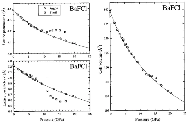
FIG. 13. Effect of two different pressure-transmitting media (silicone oil and argon) on the compression of BaFCl. A low proportion of powder was placed into the gasket hole. Circles (squares): argon (silicone oil) pressure-transmitting medium.
IONIC LAYERED PbFCl-TYPE COMPOUNDS UNDER... 4019
FIG. 14. Effect of two different pressure-transmitting media (silicone oil and argon) on the compression of BaFBr. A low proportion of powder was placed into the gasket hole. Circles (squares): argon (silicone oil) pressure-transmitting medium.
bonding scheme than a quasitridimensional crystal like BaFCl. The previous results have shown that the layered character of a matlockite M FX is linked to the size of the X halogen: an increase of the X-atom size tends to reduce the structure compactness. Because the electronic polarizability is directly proportional to the atomic size, we introduce the
polarizability œx of the X halogen anion since we expect that
it might be important in determining the equilibrium struc- ture of ionic-layered compounds.
In the classical theory of ionic crystals,28 the cohesive energy can be written as the sum of the Madelung and a repulsive energy:
FIG. 15. Effect of two different pressure-transmitting media (silicone oil and argon) on the compression of BaFI. A low proportion of powder was placed into the gasket hole. Circles (squares): argon (silicone oil) pressure-transmitting medium.
2 x
FIG. 16. BaFCl volume compression obtained with two differents pressure-transmitting media (silicone oil and argon).
Ecoh=EMad+Erep=-
NAZ2e2
R +NBR-n (5)
M F2 and MX2 : the M F2 sublattice is formed by corner- shared cation tetrahedra centered around a fluorine. The sec- ond sheet MX2 is made up of edge-shared cation pyramids where N is the number of cations in the crystal, A the Made-
lung constant, Ze the charge of the anion, R the shortest anion-cation distance, B the repulsive constant, and n a posi- tive integer number. It has been shown29 that zero-point mo- tions of nuclei and van der Waals forces produce only small contributions to the lattice energy and, hence, they are ig- nored in the discussion that follows.
For layered-ionic compounds, because of the large polar- izability of the X anion (in Debye units,30 œCl=2.96, œBr =4.16, œI=6.43), we may expect that electric dipole mo- ments play an active role in their static and dynamic properties.31,32 In order to account for this effect, a contribu- tion to the cohesive energy due to the local electric field E on the highly polarizable X anion is included in the previous model:
NAZ2e2
inside which the halogen X has an asymmetric coordination, which means that the halogen is equidistant from the four basal plane M ' cations (distances M 'X) but at a different
distance from the M " apex cation (distance M "X) (see Table
V and Fig. 12).
A simple calculation of the local electric field inside the pyramid is proposed in Appendix B. This calculus allows to determine the variation of the C parameter as a function of the halogen position around the cations pyramid. This con- stant is larger for a distorted structure (like the Ba5-I pyramid of BaFI with a large asymmetric coordination of the I an- ions) than for a quasitridimensional compound (such as BaFCl, where the quasisymmetric coordination of Cl tends to cancel the polarization energy).
A rigorous calculation using the Bertaut method33 of the total polarization energy for the three BaFX compounds has
Ecoh=E Mad+Erep+Epol=- R +NBR-n- 1 Nœ E2.
(6)
been also performed on the basis of Eq. (7). The result, which is summarized in Table VI, shows a strong depen- dence of the polarization energy with the halogen size, which In a first approximation, the local electric field E is deter-
mined by point charges of the neighboring ions around the X halogen. It leads to an energy contribution
NCZ2e2œ
x
is consistent with the simple calculation of the C parameter variation in Appendix B.
V. CONSEQUENCES OF THE X HALOGEN CHARACTERISTICS ON THE LAYERED PROPERTIES
Epol=-
R4 , (7) The large polarizability and asymmetrical coordination of where C is a dimensionless constant that depends on the
structure.
B. Application to the matlockite family
The atomic arrangement in the matlockite structure, illus- trated in Fig. 12, is obtained by stacking alternate sheets of
the X halogen atom allow us to understand the stability of ionic layered crystals.
(i) Contribution of the polarization energy to the structure
stability. The structure of ionic layered compounds is stabi-
lized by the combined effect of the halogen anisotropic co- ordination [increasing the C value in Eq. (7)] and the large polarizability that lead to large static dipoles on the anions
IONIC LAYERED PbFCl-TYPE COMPOUNDS UNDER... 4021
FIG. 17. Position of the halogen atom X in the cations pyramid.
and give an extra-energy term to the quasitridimensional lat- tice energy.
(ii) Effect of the halogen atom polarization on the com-
pressibilities. In terms of stability, the considerations above
show that the most favorable M FX crystal structure is ob- tained for an asymmetric position of highly polarizable halo- gen atoms. Hence, the distance between the halogen planes must be larger than for an isotropic coordination, leading to a layerlike structure. The weak bonds between the halogen planes increase the linear compressibility along C4 . The lin- ear compressibility perpendicular to C4 are only due to a simple steric dimension effect, in relation to a classical ionic structure.
(iii) Redistribution of the halogen coordination under
pressure. The anisotropic bonding forces between ions in
this layered structure are related to the nonequidistant posi- tion of the halogen atom around the cations. Therefore, the pressure, which affects primarily the weak bonds, may lead to a redistribution of the halogen coordination, decreasing the C-constant value of Eq. (7) down to its minima, and, hence, causing the polarization on the halogen to vanish. In this way, the pressure evolution of the BaFI c/a ratio is significant: from 0 to about 15 GPa (V/V0=0.83), the strong decrease of the ratio, compared to that of BaFCl or BaFBr, could indicate a kind of gradual layer-nonlayer transforma- tion.
VI. CONCLUSION
The observed anisotropy of layered compounds appears to be a direct consequence of the bonding-type anisotropy in- side their structures. For example, it is now well established34 that the layered covalent crystals exhibit two distinct kinds of bonding, a covalent one inside the layers with van der Waals type forces between the slabs. The situ- ation appears to be quite different for ionic-layered com- pounds such as BaFX (which may also be right for other ionic-layered compounds like PbI2 or CdX2), where only one type of force is present. A layer structure for ionic crystals with large halogen atoms (high polarizability due to the large size) appears to be the most favorable framework in terms of stability. Hence, the anisotropic position of the halogen at- oms modulate the magnitude of the Coulomb forces along
FIG. 18. Variation of the C parameter of Eq. (7) as a function of the relative halogen position in the pyramid z/R [see Eq. (B1)]. At
z/R=0, the halogen atom is at the pyramid center of mass (X0). the direction parallel to the C4 axis in order to create halogen slabs weakly bonded together. The present x-ray-diffraction experimental results allowed us to deduce and argue the as- sumptions above that give a new contribution to the under- standing of how the pressure affects condensed matter.
ACKNOWLEDGMENTS
We would like to gratefully acknowledge Michel Gauthier and Marcos Grimsditch for helpful comments and discussions. Physique des Milieux Condense´s is unite´ mixte de recherche n° 7602 of the CNRS.
APPENDIX A: HYDROSTATIC LIMITS OF SILICON OIL AS A PRESSURE-TRANSMITTING MEDIUM
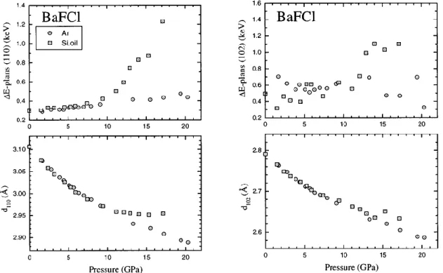
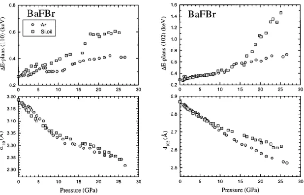
To illustrate how the pressure-transmitting media may af- fect the quality of the lattice parameters determination in BaFCl, BaFBr, and BaFI, we report in Figs. 13–15, respec- tively, the pressure-width dependence of two diffraction lines (110) and (102), involving for the first one the a( P) variation and, for the second one, the coupled a( P) and c(
P) variation. We note, starting at about 10 GPa, a strong and
gradual broadening of the diffraction lines when the ex- periment is performed with silicone oil. At the same time, a jump in the value of the lattice parameter and a broadening of the ruby line were also observed. This effect, commonly observed in high-pressure experiments (e.g., Refs. 35–37) may be ascribed to the glass transition of the pressure me- dium. On the other hand, no strong dependence with pressure of the diffraction linewidths was noted when argon was used. From 0 to 10 GPa, the lattice parameters obtained with the two different media are in good agreement. At higher pres- sure, the variation of the a and c parameters should only be discussed when the experiment was performed with argon. Surprisingly, in the whole pressure range, we noted that the shifts on these parameters due to the nonhydrostatic property of silicone oil seem to complement each other in order to give the ‘‘argon value’’ of the cell volume (illustrated in Fig.
(
016), but we cannot account for this.
We also performed experiments on BaFCl and BaFI with different quantities of powder (and with the same pressure- transmitting medium): when the gasket hole was full of pow-
For z=0(<P=<P0); E=0, which leads to <P0
=arcsin(1/4). For small z (for BaFI, the most layered com- pounds of the three studied, z~0.1 Å�R~3.6 Å), one can approximate <P to <P0 in Eq. (B1). We obtain
der, the experimental results were not reproducible, and did
(
not agree with previously published data.
APPENDIX B: SIMPLE CALCULATION OF THE LOCAL ELECTRIC-FIELD VARIATION WITH THE
E=Ze 1 ( R+z )2 -R2- 1 Rz +z2 2 z z . (B2) HALOGEN POSITION
Let M " be the apex pyramid cation, M ' the corners of the expressed as function of z: By analogy with Eq. (7), the constant C can therefore be pyramid base square, and X0 the position of the cation-
(
pyramid center of mass (M "X =M 'X =R; see Fig. 17). For
R4 1 1 2
0 0 C=
2- , (B3)
an asymmetric position X of the halogen at a distance (R +z) from the apex cation M ", the local electric field is given by 2 ( R+z ) R2- Rz +z2 2 Ze E= ( R+z )2-4 ( R cos <P Ze z )2+( R sin <P -z )2sin <P z ,
which, in the approximation of small z, leads to 25
(
z2(B1) where Ze is the charge of the anion and <P the (MX,MP)
C=
8 R . (B4) angle. The first term of Eq. (B1) corresponds to the electric
field on the halogen due to the M " cation, and, for the second term, to the electric field due to the 4M ' cations.
The evolution of C as a function of z is given in Fig. 18, showing the increase of C for an asymmetric position of the halogen atom around the cation pyramid.
*Electronic address: [email protected]
1 B. Liebich and D. Nicollin, Acta Crystallogr., Sect. B: Struct.
Crystallogr. Cryst. Chem. 33, 2970 (1977).
2 M. Sauvage, Acta Crystallogr., Sect. B: Struct. Crystallogr. Cryst.
Chem. 30, 2786 (1974).
3 H. P. Beck, J. Solid State Chem. 17, 275 (1976).
4 M. Pasero and N. Perchiazzi, Miner. Mag. 60, 833 (1996). 5 NBS Monogr. 25, Sec. 10, 26 (1972); 25, Sec. 13, 25 (1976). 6 F. Hulliger, Structural Chemistry of Layer-Type Phases (Reidel,
Dordrecht, 1975), pp. 258–264.
7 K. Tkahashi, J. Miyahara, and Y. Shibahara, Electrochem. Soc.
Interface 132, 1492 (1985).
8 Y. R. Shen, T. Gregorian, and W. B. Holzapfel, High Press. Res.
7, 73 (1992).
9 F. Datchi, PhD thesis, University of Paris, 1997.
10 Y. R. Shen, U. Englisch, L. Chudinovskikh, F. Porsch, R.
Haberkorn, H. P. Beck, and W. B. Holzapfel, J. Phys.: Condens. Matter 6, 3197 (1994).
11 F. Decremps, M. Fischer, A. Polian, and M. Sieskind, High
Temp.-High Press. 30, 235 (1998).
12 K. R. Balasubramanian, T. M. Haridasan, and N. Krishnamurthy,
Chem. Phys. Lett. 67, 530 (1979).
13 G. R. Thompson and J. Turk, Modern Physical Geology, 2nd ed.
(Saunders College, New York, 1997), p. 50.
14 M. Sieskind, M. Ayadi, and G. Zachmann, Phys. Status Solidi B
136, 489 (1986).
15 R. Letoullec, J. P. Pinceaux, and P. Loubeyre, High Press. Res. 1,
77 (1988).
16 J. D. Barnett, S. Block, and G. J. Piermarini, Rev. Sci. Instrum.
44, 1 (1973).
17 A. Boultif and D. Louer, J. Appl. Crystallogr. 24, 987 (1991). 18 N. Subramanian, N. V. Chandra Shekar, P. Ch. Sahu, Mohammad
Yousuf, and K. Govinda Rajan, Phys. Rev. B 58, R555 (1998).
19 F. Decremps, M. Fischer, A. Polian, J. C. Chervin, and M. Sies-
kind (unpublished).
20 F. Birch, J. Geophys. Res. 57, 227 (1952). 21 F. Birch, J. Geophys. Res. 83, 1257 (1978).
22 F. Decremps, M. Fischer, A. Polian, and M. Sieskind, Eur. Phys.
J. B 5, 7 (1998).
23 G. Kalpana, B. Palanivel, and I. B. Shameem Banu, Phys. Rev. B
56, 3532 (1997).
24 M. Sieskind, A. Polian, M. Fischer, and F. Decremps, J. Phys.
Chem. Solids 59, 75 (1998).
25 M. Fischer, A. Polian, and M. Sieskind, J. Phys.: Condens. Matter
6, 10 407 (1994).
26 M. Fischer, M. Sieskind, A. Polian, and A. Lahmar, J. Phys.:
Condens. Matter 5, 2749 (1993).
27 F. Decremps, M. Fischer, A. Polian, J. P. Itie´, and M. Sieskind,
Eur. Phys. J. B (to be published).
28 M. Born and K. Huang, Dynamical Theory of Crystal Lattices
(Oxford Univ., London, 1954).
29 M. Sieskind and J. Morel (unpublished).
30 J. R. Tessman and A. H. Kahn, Phys. Rev. 92, 890 (1953). 31 E. F. Bertaut, C. R. Acad. Sci., Ser. II: Mec., Phys., Chim., Sci.
Terre Univers 302, 285 (1986).
32 C. Haas, in Proceedings of the Yamada Conference IV, edited by
Y. Nishina [Physica B 105, 305 (1981).
33 E. F. Bertaut, J. Phys. (Paris) 39, 1331 (1978). 34 A. Polian, PhD thesis, University of Paris, 1981.
35 J. C. Chervin, B. Canny, J. M. Besson, and Ph. Pruzan, Rev. Sci.
Instrum. 66, 2595 (1995).
36 J. W. Otto, J. K. Vassiliou, and G. Frommeyer, Phys. Rev. B 57,
3253 (1998).
37 J. M. Le´ger, A. M. Redon, and C. Chateau, Phys. Chem. Miner.
17, 161 (1990). 0