HAL Id: hal-01335643
https://hal.archives-ouvertes.fr/hal-01335643
Submitted on 22 Jun 2016
HAL is a multi-disciplinary open access
archive for the deposit and dissemination of
sci-entific research documents, whether they are
pub-lished or not. The documents may come from
teaching and research institutions in France or
abroad, or from public or private research centers.
L’archive ouverte pluridisciplinaire HAL, est
destinée au dépôt et à la diffusion de documents
scientifiques de niveau recherche, publiés ou non,
émanant des établissements d’enseignement et de
recherche français ou étrangers, des laboratoires
publics ou privés.
Magnetic field, temperature and velocity distribution
measurements in an electromagnetic induction pump
using a small ferrite core coil system
L Goldšteins, C Biscarrat, L Buligins, Y Fautrelle, E Platacis, A Romančuks,
A Fļerovs
To cite this version:
L Goldšteins, C Biscarrat, L Buligins, Y Fautrelle, E Platacis, et al.. Magnetic field, temperature
and velocity distribution measurements in an electromagnetic induction pump using a small ferrite
core coil system. 8th International Conference on Electromagnetic Processing of Materials, Oct 2015,
Cannes, France. �hal-01335643�
Magnetic field, temperature and velocity distribution measurements in an electromagnetic
induction pump using a small ferrite core coil system.
L. Goldšteins
1, C. Biscarrat
1, L. Buligins
2, Y. Fautrelle
3, E. Platacis
4, A. Romančuks
4, A. Fļerovs
41 CEA, CADARACHE, DTN/STPC/LCIT Bat. 204, 13108 St. Paul lès Durance, France 2University of Latvia/Faculty of Physics and Mathematics, Zeļļu 8, LV-1002, Riga, Latvia 3
Grenoble INP, SIMAP/EPM Laboratory, Domaine Universitaire, 38402, St. Martin d’Héres, France
4
Institute of Physics University of Latvia, Miera 32, LV-2169, Salaspils, Latvia
Linards Goldsteins: [email protected]
Abstract
In this paper technique of local AC magnetic field, temperature and velocity measurements in the gap between electromagnetic induction pump (EMIP) channel and inductor using a single ferrite core coil is discussed.
Described method has several important advantages: high signal/noise ratio due to ferrite core, small size of a sensor, three parameter measurement, non-intrusiveness, low cost etc. However, some significant limitations should be also considered: saturation of ferrite core with relatively low fields and temperature dependence on magnetic permeability characteristic of ferrite material.
Finally, this perspective measurement method was tested in University of Latvia (UL) and implemented in measurement system of TESLA-EMP loop in Institute of Physics of University of Latvia (IPUL). Some relevant results of these experiments are presented.
Key words: Temperature, velocity, ferrite, coil, ASTRID. Introduction
AC magnetic field measurements using coils are well known since epoch of Faraday which law of induction is fundamental principle of this technique. Similar can be said about change of conductivity/resistivity of metallic wire as function of temperature, it strictly defined by properties of wire material and size.
These measurements can be done using commercially available small sized ferrite core coils. Ferrite is used to improve strength of signal, but disadvantage is non-linearity with high magnetic field (saturation) and (Curie) temperature, which must be taken into account.
EMIP is asynchronous electrical machine which uses traveling magnetic field to create EM force and motion of liquid metal. Induced magnetic field in EMIP is a function of liquid metal velocity [1], therefore magnetic field measurement contain information about the flow structure in the channel.
In the context of ASTRID (Advanced Sodium Technological Reactor for Industrial Demonstration) R&D program large scale Annular Linear Induction Pump (ALIP) called PEMDYN will be tested [2]. In support of these activities TESLA-EMP (Test and Experimental Sodium Loop for Analysis of ElectroMagnetic Pumps) facility in IPUL [3] is developed. One of the goals of these studies is to improve experimental investigation methods in EMIP.
Signal characterization of ferrite core coils
In all experiments EPCOS B82451N coils were used measuring: 7.7 mm diameter and 2.65 mm height. A set of experiments in UL were carried out to determine non-nonlinear behavior and better understand usage of such device.
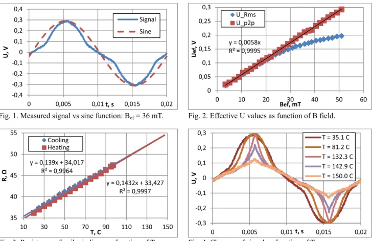
First of all, experiments showed that by using known external AC field with 50 Hz frequency, ferrite core starts to saturate with relatively low fields and gives output signal somewhat different from sine (fig. 1). This leads to nonlinear RMS signal, however, effective value calculated from peak-to-peak (maximum, minimum) keeps linearity (fig. 2), due to fact that EMF and external field are 90° shifted (Faradays’ law). In other words, at peaks of the measured signal instantaneous value of external field is 0 (no saturation of core possible) and value of amplitude is preserved (fig. 1).
Secondly, graduation of coil wire resistance as function of temperature was carried out by heating and then cooling water with immersed small coil and thermocouple which gave linear relationship (fig. 3). Then in different setup signal was analyzed with oscilloscope as function of temperature (determined by resistance) by convectively heating coil in the ceramic tube inside known external field using hot air gun. Result showed that even form of signal changes with temperature, peaks are preserved up to 130°C (fig. 4).
Fig. 1. Measured signal vs sine function: Bef = 36 mT.
Fig. 3. Resistance of coil windings as function of T.
Fig. 2. Effective U values as function of B field.
Fig. 4. Changes of signal as function of T.
Apparently the problem of linear magnetic field measurement using ferrite core coil is about finding peak-to-peak values and controlling its temperature. Since peaks become narrower with increase of both – amplitude of magnetic field and temperature, good temporal discretization is required.
Implementation in TESLA-EMP setup
In TESLA-EMP facility flat EMIPs with double sided inductors are used, which allows easier implementation of magnetic field measurements. Between inductors stainless steel cannel filled with Na was placed asymmetrically to equip lower inductor with magnetic field samplers on the Fe tooth between each two coils of the same phase (A-A, B-B etc.) (fig. 5). 18 rows of samplers were fixed on the inductor (fig. 6), in each row there were 2 samplers and each of them had 4 measurement coils soldered on PCB (fig .7). The thickness of sampler was around only 3 mm. Totally 144 measurement points gave 50x60 mm spatial resolution of the channel active part with dimensions 420x1080 mm.
Fig. 5. Schema of EMIP and sampler placement. Fig. 6. 144 point measurement realization.
Fig. 7. In-house developed sampler: L x W x H = 300 x 15 x 3 mm. -0,4 -0,3 -0,2 -0,1 0 0,1 0,2 0,3 0,4 0 0,005 0,01 0,015 0,02 U, V t, s Signal Sine y = 0,139x + 34,017 R² = 0,9964 y = 0,1432x + 33,427 R² = 0,9997 35 40 45 50 55 10 30 50 70 90 110 130 150 R, Ω T, C Cooling Heating y = 0,0058x R² = 0,9995 0 0,05 0,1 0,15 0,2 0,25 0,3 0 10 20 30 40 50 60 U ef , V Bef, mT U_Rms U_p2p -0,3 -0,2 -0,1 0 0,1 0,2 0,3 0 0,005 0,01 0,015 0,02 U, V t, s T = 35.1 C T = 81.2 C T = 132.3 C T = 142.9 C T = 150.0 C
Temperature measurement was performed by adding voltage divider on each coil using Us = 12V and R1 =
12KΩ and connected to data acquisition system, as shown in (fig. 8), working with 2KHz. EMIP was driven by 50 Hz motor generator and operation temperature of loop was on average 150°C. Cooling of measurement coils was
realized by forced air convection with 4 ventilators. Fig. 8. Circuit diagram for voltage measurements. Results
First of all, results with applied line current I = 200 [A] and flowrate Q = 3 [l/s] of magnetic field (fig. 9) and temperature (fig. 10) measurements averaged over 1s are presented, which represent global behavior of the system. It can be observed that distribution of magnetic field is rather symmetric with higher values in the side zones which correspond to transversal end effects of flat type EMIP. Temperature distribution in (fig. 10) represents ventilator cooling from the one side of the channel and it is shown that maximally it reaches 70ºC, which is acceptable.
Fig. 9. Obtained average distribution of B: Q = 3[l/s]. Fig. 10. Obtained average distribution of T: Q = 3[l/s].
Fig. 11. Temporal behavior of B: Q = 3[l/s], t = 1.40[s].
Fig. 13. Temporal behavior of B: Q = 3[l/s], t = 1.80[s].
Fig. 12. Temporal behavior of B: Q = 3[l/s], t = 1.60[s].
Fig. 14. Temporal behavior of B: Q = 3[l/s], t = 1.98[s]. Next, it is possible to analyze transient behavior of magnetic field with the time step as small as 0.02s, which corresponds to period of 50Hz frequency. It can be seen in (fig. 11- 14) that certain fluctuations of magnetic field are captured and are rather periodic. However, globally distribution of magnetic field resembles to averaged field in (fig. 9). Finally, a regime with higher flowrate Q = 25 [l/s] is presented in (fig. 15 - 18) where interesting phenomenon is observed – not only magnetic field fluctuates, but its symmetry has been completely lost as well. Such behavior should be connected with strongly vortical flow, in some sense characterizing MHD instability.
Fig. 15. Temporal behavior of B: Q = 25[l/s], t = 1.40[s].
Fig. 17. Temporal behavior of B: Q = 25[l/s], t = 1.60[s].
Fig. 16. Temporal behavior of B: Q = 25[l/s], t = 1.50[s].
Fig. 18. Temporal behavior of B: Q = 25[l/s], t = 1.70[s]. Reconstruction of velocity field from magnetic field, first of all, implies finding axial velocity component. E.g. in the ideal ALIP axial component can be expressed as:
𝑣𝑧= 𝑣𝐵[1 − 𝑅𝑚−1√(𝐵0/𝐵)2− 1] (1)
Where: 𝑣𝐵 – velocity of magnetic field; 𝑅𝑚 – Magnetic Reynolds number; 𝐵0 – amplitude of external magnetic field; 𝐵 – amplitude of total magnetic field (measured).
Then, azimuthal velocity component can be derived from continuity equation.
Here the reconstruction has not been done, since in the case of flat EMIP it is more challenging due to transversal end effects. However, we consider it as primary task to develop contactless velocity measurement technique in EMIP. Conclusions and discussion
A detailed magnetic field and temperature measurement technique in air gap of EMIP using system of small ferrite core coils have been developed, successfully implemented and tested in operation. Overall, this robust method has great capabilities and potential to be developed further.
The first results of the distribution of magnetic field have shown some unexpected fluctuation and loss of symmetry, which are likely correlated with hydrodynamic behavior of liquid sodium in the channel. However, precise methodology to recalculate velocity distribution is still necessary.
Since the presented technique essentially relies on the frequency of the applied current in the inductor, it was a natural limit of the available (measurable) frequency band in presented case. Note that it is possible to improve measurements temporal resolution twice by increasing acquisition frequency – precisely measuring the peak in each half period.
Additional attention to filtering methods should be applied in case of electronically modulated AC current sources are used for alimentation of inductors.
Acknowledgment
This work has been supported by the European Social Fund within the project «Support for Doctoral Studies at University of Latvia».
References
[1] J. Lielpeters (1969), MHD machines using liquid metals, Zinatne
[2] G. Rodriguez et al (2013), Intl. Conf. on fast reactor and related fuel cycles, Paris (France), Paper CN-199-122 [3] L. Goldsteins et al (2014), 9th International PAMIR Conference, vol. 1, 51 – 54
![Fig. 11. Temporal behavior of B: Q = 3[l/s], t = 1.40[s].](https://thumb-eu.123doks.com/thumbv2/123doknet/13032559.381959/4.892.77.799.374.977/fig-temporal-behavior-b-q-l-s-t.webp)
![Fig. 15. Temporal behavior of B: Q = 25[l/s], t = 1.40[s].](https://thumb-eu.123doks.com/thumbv2/123doknet/13032559.381959/5.892.85.809.122.501/fig-temporal-behavior-b-q-l-s-t.webp)
![[PDF] Cours Algorithmique et programmation : les bases du VBA | Cours informatique](data:image/gif;base64,R0lGODlhAQABAIAAAP///wAAACH5BAEAAAAALAAAAAABAAEAAAICRAEAOw==)