The MIT Faculty has made this article openly available.
Please share
how this access benefits you. Your story matters.
Citation
Han, Y., and D.J. Perreault. “Analysis and Design of High Efficiency
Matching Networks.” IEEE Trans. Power Electron. 21, no. 5 (n.d.):
1484–1491. © 2006 IEEE
As Published
http://dx.doi.org/10.1109/TPEL.2006.882083
Publisher
Institute of Electrical and Electronics Engineers (IEEE)
Version
Final published version
Citable link
http://hdl.handle.net/1721.1/86989
Terms of Use
Article is made available in accordance with the publisher's
policy and may be subject to US copyright law. Please refer to the
publisher's site for terms of use.
Analysis and Design of High Efficiency Matching Networks
Yehui Han, Student Member, IEEE, and David J. Perreault, Senior Member, IEEE
Abstract—This letter presents analysis and design
consider-ations for lumped (inductor and capacitor) matching networks operating at high efficiency ( 95%). Formulas for calculating matching network efficiency are given, and it is shown that effi-ciency can be expressed as a function of inductor quality factor , capacitor quality factor , and transformation ratio. These formulas are used to evaluate the optimum number of -section matching stages as a function of conversion ratio. Both simulation and experimental results are presented that validate the analytical formulation.
Index Terms—Impedance transformer, matching network,
reso-nant converter.
I. BACKGROUND
A
matching network is a passive two-port circuit designed to provide narrow-band impedance and voltage transfor-mation between the two ports. While most widely associated with communications applications [1]–[3] matching networks also find useful application in resonant inverters, rectifiers, and dc-dc converters. Most analytical descriptions of matching networks are based on the assumption of no loss. Where ef-ficiency is considered [4], it is typically treated as secondary to other performance goals, in accordance with the needs of communications applications. Moreover, literature focusing on the design of matching networks for very high efficiencies (e.g., 95%) appears to be lacking. This letter presents analysis and design considerations for high efficiency lumped-element matching networks.In Section II, some possible topologies for matching net-works are identified, and formulas to calculate their efficiency are developed. In Section III, the implications of the results of Section II are discussed, and the analytical results are compared to Pspice simulations. Strong agreement between analysis and simulation is demonstrated. Section IV presents experimental results validating the efficiency calculations of Section II. Finally, Section V concludes the letter.
II. MATCHINGNETWORKDESIGN ANDEFFICIENCYANALYSIS
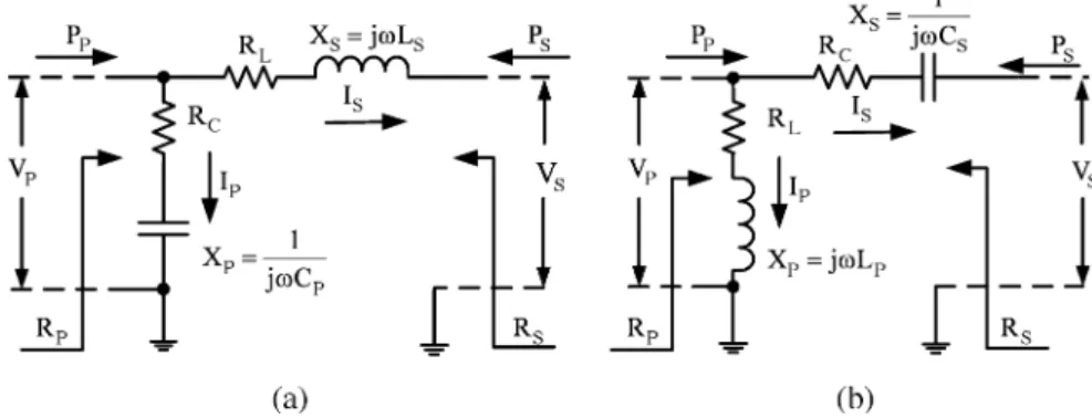
Two basic matching network topologies are shown in Fig. 1. Fig. 1(a) and (b) are low-pass and high-pass single-stage -sec-tion matching networks. These networks can be used to step a load impedance up or down, depending upon which port is con-nected to the load and which is concon-nected to the source [1]. They
Manuscript received January 20, 2006; revised April 11, 2006. Recom-mended for publication by Associate Editor J. Sun.
The authors are with the Laboratory for Electromagnetic and Electronic Systems, Massachusetts Institute of Technology, Cambridge, MA 02139 USA (e-mail: yehuihan@mit.edu).
Digital Object Identifier 10.1109/TPEL.2006.882083
can each be used to transform a load resistance of value con-nected to the right-hand port to a resistance seen from the left-hand port, or to transform a load resistance of value con-nected at the left-hand port down to a resistance seen from the right-hand port. T and matching networks could also be used as basic matching networks. However, they invariably have lower efficiency than an equivalent -section network [2] and are thus not considered here. Inductor parasitic resistance and capacitor parasitic resistance are shown as explicit cir-cuit elements in each network of Fig. 1. and are the peak voltages at the left-hand and right-hand ports. and are the peak currents in the shunt and series legs.
Design of the matching networks of Fig. 1 (neglecting , , and the loss associated with them) is well understood [1]–[3] and may be carried out as follows. Starting with a desired resistance transformation ratio
(1)
we can define an associated transformation quality factor
(2)
a series-leg quality factor
(3)
and a shunt-leg quality factor
(4)
As shown in Fig. 1, is the quality factor of the series leg (where we include the external network resistances and neglect matching network loss) and is the quality factor of the shunt leg; is the matched shunt resistance; is the shunt re-actance; is the matched series resistance and is the se-ries reactance. To achieve the desired transformation neglecting loss, the matching network reactances are selected such that
.
Losses in high-efficiency matching networks can be com-puted using the following approximation: the circuit is designed and the circuit currents are calculated on a no-loss basis; the in-ductor and capacitor losses and circuit efficiency are then cal-culated based on the losses induced by the calcal-culated currents flowing through inductor resistance and capacitor resistance
. This calculation thus assumes that the branch currents are not affected by the presence of small resistive components [2].
Shown in Fig. 1, is the power entering the matching net-work from the right, is the power entering the matching net-work from the left. We get
(5)
(6)
is the loss power in the capacitor, is the loss power in the inductor, is the total loss power in the matching network and equal to .
Consider, first, the low-pass matching network shown in Fig. 1(a). is the quality factor of the inductor, 1 is the quality factor of the capacitor, and represents the efficiency of the matching network. From Fig. 1(a) and above definitions, we have
(7)
(8)
If the left port is connected to the source and the right port is connected to the load, is positive and is negative
(9)
(10)
If the left port is connected to the load and the right port is connected to the source, is negative and is positive
(11)
(12)
Next consider the high-pass matching network shown in Fig. 1(b). The inductor quality factor
and the capacitor quality factor 1 . From Fig. 1(b) and above definitions, we have
(13)
(14)
If the left port is connected to the source and the right port is connected to the load, is positive and is negative
(15)
(16)
If the left port is connected to the load and the right port is connected to the source, is negative and is positive
(17)
(18)
When 1 and 1 (i.e., for the case of high efficiency), we can approximate (10), (12), (16), and (18) by neglecting products of these small quantities. In each case, this yields
(19)
Notice we get the same efficiency for the low-pass and high-pass matching networks if and (i.e., for the case of high efficiency). Moreover, for most cases of practical interest, , inductor loss far exceeds capacitor loss and is the only loss component that needs to be considered. In this case
(20)
It is important to observe that the matching network efficiency depends only on the inductor quality factor and the transforma-tion ratio if . For a given inductor quality factor, there is an upper bound on the efficiency of a single-stage matching network as expressed in (20).
Fig. 1. L-section matching networks with inductor parasitic resistance shown explicitly: (a) Low-pass and (b) high-pass.
Fig. 2. Multistage matching network.
One route towards higher performance that is sometimes recommended is the use of a multistage matching network comprising a cascade of individual -sections [2]. Consider the -stage matching network illustrated in Fig. 2. Using (20) and assuming that all inductors’ are identical, we get
(21)
where is the transformation quality factor of the th stage [corresponding to the transformation ratio of one stage in (1) and (2)]. For high efficiency of each stage we require 1, and find:
(22)
and from the formulas in [5], it can be shown that
only when
(23)
Thus, for the optimal case of identical transformation ratios for each -section stage, we select the transformation quality factors of all the stages as
(24)
and achieve an overall efficiency of
(25)
Considering (25), there is clearly an optimum number of stages to maximize efficiency. This number is a function of the trans-formation ratio but not a function of inductor quality factor , assuming all inductors have an identical specified . Fig. 3 plots the optimum number of -section stages as a func-tion of the voltage transformafunc-tion ratio . As transforma-tion quality factor increases, the optimum number of stages approaches
(26) and the efficiency approaches
(27)
where is as defined in (2). These results indicate that using multi-stage design may improve the efficiency, especially when the desired transformation ratio is very large. But the efficiency
Fig. 3. Optimum number of stages versus transformation ratio.
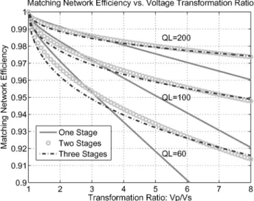
Fig. 4. Matching network efficiency versus transformation ratioV =V .
reaches its maximum at a certain number of stages and will de-crease for more stages.
III. CALCULATION ANDSIMULATIONRESULTS
The previous section showed that matching network effi-ciency can be expressed as a function of inductor quality factor and transformation ratio. To illustrate the implication, Fig. 4 plots predicted matching network efficiency versus trans-formation ratio for three different inductor quality factors used in one-, two-, and three-stage designs. In all cases, matching network efficiency decreases with increasing transformation ratio, and decreases more rapidly with lower inductor quality factor. This is to be expected, given the forms of (20) and (25). Fig. 4 also illustrates how the optimal number of matching network stages changes with transformation ratio for a speci-fied inductor . Consider the one, two and three-stage design curves for 60. For a voltage transformation ratio of 2, a
Fig. 5. Matching network efficiency versus inductor quality factor.
single-stage design has the highest efficiency. At a voltage trans-formation ratio of 5, a two-stage design has a significant advan-tage ( 1.5%) in efficiency over a single-sadvan-tage, and at a voladvan-tage transformation ratio of 8, the three-stage design is developing a marginal advantage over a two-stage design. Considering the tradeoffs at a voltage conversion ratio of 8, it can also be seen that if the space required to construct the three inductors for the three-stage 60 design can be employed to build a higher inductor for a single-stage design (e.g., 100), then a single-stage design may still be preferable. Thus, the optimal number of stages specified in Fig. 3 and (25) should only be considered an upper bound.
Fig. 5 illustrates the predicted efficiency of a matching net-work for a typical voltage transformation ratio of 4 as a function of inductor quality factor (parameterized by the number of stages). In each curve, percentage loss is inversely proportional to (20), (25) leading to the observed asymptotic behavior. Thus, for a single-stage design, doubling quality factor from 100 to 200 yields an efficiency improvement from (approxi-mately) 96% to 98%, and doubling again to 400 changes efficiency from 98% to 99%. Still greater loss reductions require proportionally higher inductor quality factors, and under thqose conditions the capacitor quality factor starts to be a consider-ation (limiting efficiency) as indicated in (19). Nevertheless, it may be concluded that for a 4:1 voltage transformation ratio, it is possible to achieve high efficiency with inductors of reason-able quality factor. To further illustrate component sizing and efficiency, consider the design of matching networks having a voltage transformation ratio of 4:1. We assume 25 W, 50 , and 16 3.125 .
The component values for the matching networks of Fig. 1(a) and (b) are shown in Table I for frequencies of 25, 50, and 100 MHz. For the multistage network in Fig. 2, we assume that the shunt components are all inductors, the series
TABLE I
COMPONENTVALUES FOR THEMATCHINGNETWORKS OFFig. 1(a)AND(b)FORR = 50 ANDR = 3.125
TABLE II
COMPONENTVALUES FOR THEMULTISTAGEMATCHINGNETWORK INFIG. 2FORR = 50 ANDR = 3.125
TABLE III
CALCULATED ANDSIMULATEDRESULTS FOR THEMATCHINGNETWORKS INFIG. 1ANDFIG. 2
components are all capacitors, and the for each stage is the same. The component values for two- and four-stage designs are shown in Table II.
Efficiency results are listed in Table III for both calculated values using (20) and (21) and for simulations of the circuits in PSPICE. The simulation results show excellent agreement with the calculations. The maximum efficiency is about 98% when 200 and approximately 93% when 60. As expected, multistage matching networks don’t provide a sig-nificant advantage (especially given the additional components required) because the required transformation ratio is not very large.
IV. EXPERIMENTALRESULTS
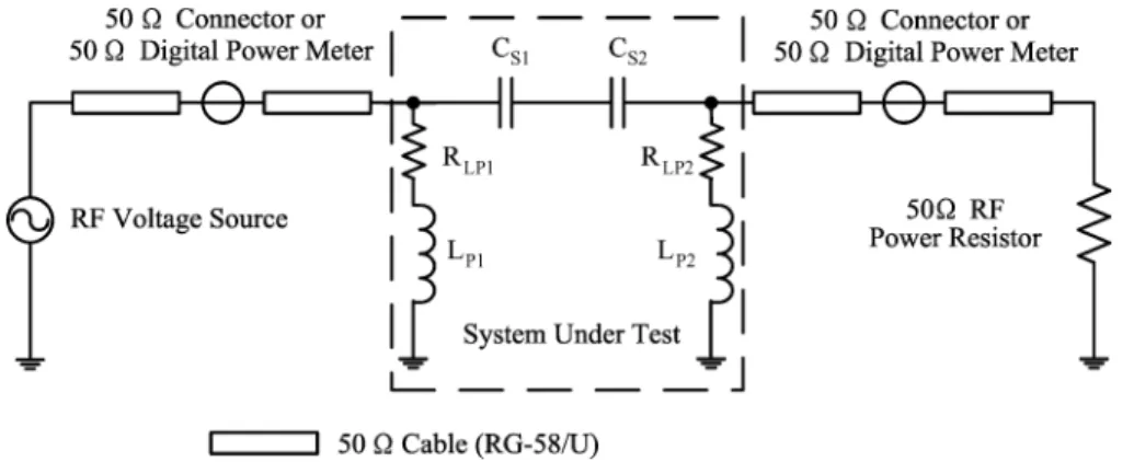
In order to verify the theoretical calculations of (20) and (25), experiments were carried out using the experimental setup of Fig. 6 (equipment indicated in Table IV). The test
setup is designed to measure the performance of back-to-back connections of identical matching networks which transform impedance away from 50 and back to 50 . Cascading matching networks in this manner provides an increased loss which is easier to measure than that of a single network. Moreover, this method enables all power measurements to be made at 50 with a single power meter, thus providing for more accurate calculation of efficiency than could be obtained otherwise.
To find matching network efficiency, the forward and re-flected powers are measured, with the same power meter, as at each of the two locations indicated in Fig. 6, and it is verified that the reflected power is low, indicating a good impedance match. (A 50- through-connector is utilized in whichever location the power meter is not used.) The efficiency of the matching network cascade is calculated as the ratio of the net power flow, forward minus reflected, measured at the load
Fig. 6. Experimental setup for validating matching network efficiency calculations. Equipment and component values are detailed in Tables IV and V. The 50- power meter can be placed in either location indicated, as described in the experimental methods.
TABLE IV
EQUIPMENTUSED IN THEEXPERIMENTALSETUP OFFIG. 6
Fig. 7. Experimental back-to-back matching network cascade used in the setup of Fig. 6. The illustrated circuit has a voltage transformation ratio to the inter-mediate node of 4.27:1.
side to that measured at the source side. This measurement and calculation procedure eliminates scale factor errors in the power measurements, e.g., due to limits on absolute accuracy of the power meter.
Fig. 7 shows a back-to-back matching network cascade for the test setup of Fig. 6. The matching network cascade has the topology indicated in Fig. 6 and is implemented on a printed circuit board with 50- BNC connectors mounted on the back side of the board. Two such matching network cascades were developed, each designed for a matched input and output resis-tance of 50 at 50 MHz. The first was designed for a voltage transformation ratio (to the intermediate node) of 3.0, while the second was designed for a voltage transformation ratio of 4.27 (selected for the ready availability of inductor values). Nominal and measured inductor and capacitor values are indi-cated in Table V along with measured circuit board parasitics.
The expected efficiency of the matching network cascade can be calculated as in (21)
(28)
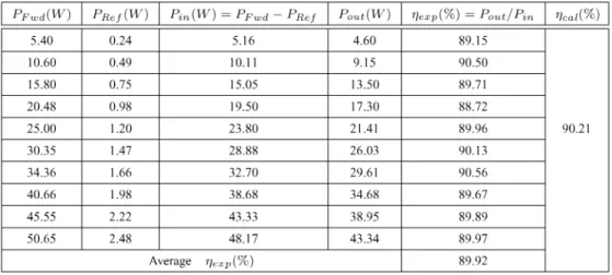
For the matching network cascade with voltage transformation ratio to the intermediate node of 3.0, 2.83 by (1) and (2). From Table V, 85.88, and 83.98. This results in a calculated efficiency 93.44%. Note that this corresponds to an ex-pected efficiency of each 3:1 stage of approximately 96.66%. Likewise, for the design with 4.27, 4.15 by (1) and (2). From Table V, 83.69, and
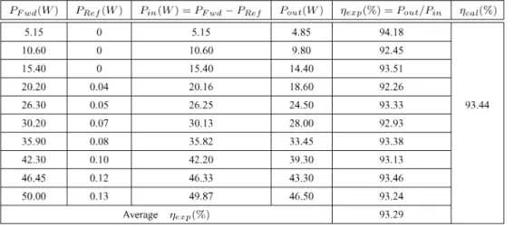
81.93, resulting in 90.21%. The experimental results for the two designs are shown in Tables VI and VII. All data were measured with the rf digital power meter. is the input forward power to the matching network cascade. Due to the component tolerances and printed circuit board parasitics, there is a small amount of mismatch between the 50- cable and the matching network input, re-sulting in a small reflected power measured by the power meter. The net input power is calculated as . Be-cause the load is a tightly specified 50- resistor and it matches well with the cable, there is no measured reflected power from the load resistor. Ten groups of data at different power levels were acquired for each design. The efficiencies are averaged to reduce the effects of sensor limitations. The average exper-imental efficiencies are very close to the theoretical results . is a little higher, at least in part, because the capac-itor losses aren’t considered in (28). From the capaccapac-itor data sheet, capacitor quality factor is roughly 1000, which accounts for 0.3% efficiency loss ( 3.00) and 0.4% efficiency loss
TABLE V
COMPONENTTYPES ANDVALUES FOR THEEXPERIMENTALMATCHINGNETWORKCASCADEUSED IN THETESTSETUP OFFIG. 6. MEASUREDVALUES FORCIRCUIT-BOARDPARASITICS AREALSOINDICATED. ALLMEASUREDVALUESWEREOBTAINED AT AFREQUENCY OF
50 MHz USING ANAGILENT4395A NETWORK/SPECTRUM/IMPEDANCEANALYZER
TABLE VI
EXPERIMENTALRESULTS FOR THEMATCHINGNETWORKCASCADEWITH ANINTERMEDIATEVOLTAGETRANSFORMATIONRATIOV =V = 3.00
( 3.00) in a single-stage matching network accounting for much of the small differences between calculated and ex-perimental results. Still more accurate calculation results can be achieved by (16) and (18). Experimental measurements thus confirm the accuracy of the models for matching network effi-ciency introduced in Section II.
It is also useful to consider the difference between the exper-imental results with a 3:1 and a 4.27:1 (intermediate) voltage transformation ratio. The design for the 4.27:1 case resulted in a higher percentage of reflected power at the matching
net-work input, corresponding to a larger mismatch between the de-sired 50 and the driving point impedance provided by the matching network cascade. This may be attributed both to the higher losses and the higher transformation quality factor in the 4.27:1 case. As increases, the design provides an increas-ingly narrow frequency band over which the desired impedance match is provided, and the impedance match becomes more sen-sitive to component tolerances. This suggests that the use of higher-order matching networks may be motivated by concerns other than efficiency if large transformation ratios are desired.
TABLE VII
EXPERIMENTALRESULTS FOR THEMATCHINGNETWORKCASCADEWITH ANINTERMEDIATEVOLTAGETRANSFORMATIONRATIOV =V = 4.27
V. CONCLUSION
This letter presents analysis and design considerations for lumped (inductor and capacitor) matching networks operating at high efficiency ( 95%). Formulas [see (19), (20), and (25)] for calculating matching network efficiency are given, and it is shown that efficiency can be expressed as a function of inductor quality factor , capacitor quality factor , and transformation ratio. These formulas are used to evaluate the optimum number of -section matching stages as a function of conversion ratio. Both simulation and experimental results are presented that validate the analytical formulation. For a typical required voltage transformation ratio of 3–5 (e.g., for a resonant dc/dc power converter design), one can expect to achieve matching network efficiencies between 96% and 98.5%
for inductor quality factors of 100–200. Efficiency can be im-proved through higher quality factor magnetics, but efficiencies exceeding 99% are likely to be challenging to achieve with this approach.
REFERENCES
[1] C. Bowick, RF Circuit Design. London, UK: Newnes, 1997, ch. 3, pp. 66–75.
[2] W. L. Everitt and G. E. Anner, Communication Engineering, 3rd ed. New York: McGraw-Hill, 1956, ch. 11.
[3] T. Lee, The Design of CMOS Radio-Frequency Integrated Circuits, 2nd ed. Cambridge, UK: Cambridge Univ. Press, 2004, pp. 87–107. [4] E. Gilbert, “Impedance matching with lossy components,” IEEE Trans.
Circuits Syst., vol. 22, no. 2, pp. 96–100, Feb. 1975.
[5] L. Rade, Mathematics Handbook for Science and Engineering, 5th ed. New York: Springer, 2004, p. 49.
