Publisher’s version / Version de l'éditeur:
ACI Structural Journal, 102, Nov/Dec. 6, pp. 883-891, 2005-11-01
READ THESE TERMS AND CONDITIONS CAREFULLY BEFORE USING THIS WEBSITE.
https://nrc-publications.canada.ca/eng/copyright
Vous avez des questions? Nous pouvons vous aider. Pour communiquer directement avec un auteur, consultez la première page de la revue dans laquelle son article a été publié afin de trouver ses coordonnées. Si vous n’arrivez pas à les repérer, communiquez avec nous à PublicationsArchive-ArchivesPublications@nrc-cnrc.gc.ca.
Questions? Contact the NRC Publications Archive team at
PublicationsArchive-ArchivesPublications@nrc-cnrc.gc.ca. If you wish to email the authors directly, please see the first page of the publication for their contact information.
NRC Publications Archive
Archives des publications du CNRC
This publication could be one of several versions: author’s original, accepted manuscript or the publisher’s version. / La version de cette publication peut être l’une des suivantes : la version prépublication de l’auteur, la version acceptée du manuscrit ou la version de l’éditeur.
Access and use of this website and the material on it are subject to the Terms and Conditions set forth at
Fire endurance of fiber-reinforced polymer-confined concrete columns
Bisby, L. A.; Kodur, V. K. R.; Green, M. F.
https://publications-cnrc.canada.ca/fra/droits
L’accès à ce site Web et l’utilisation de son contenu sont assujettis aux conditions présentées dans le site LISEZ CES CONDITIONS ATTENTIVEMENT AVANT D’UTILISER CE SITE WEB.
NRC Publications Record / Notice d'Archives des publications de CNRC:
https://nrc-publications.canada.ca/eng/view/object/?id=1fa0cb6b-03e4-4c5b-865e-fb7457d92850 https://publications-cnrc.canada.ca/fra/voir/objet/?id=1fa0cb6b-03e4-4c5b-865e-fb7457d92850http://www.nrc-cnrc.gc.ca/irc
Fire e ndura nc e of fibe r-re inforc e d polym e r-c onfine d c onc re t e
c olum ns
N R C C - 4 6 7 3 3
B i s b y , L . A . ; K o d u r , V . R . ; G r e e n , M . F .
N o v e m b e r 2 0 0 5
A version of this document is published in / Une version de ce document se trouve dans:
ACI Structural Journal, 102, (6), Nov/Dec., pp. 883-891, November 01, 2005
The material in this document is covered by the provisions of the Copyright Act, by Canadian laws, policies, regulations and international agreements. Such provisions serve to identify the information source and, in specific instances, to prohibit reproduction of materials without written permission. For more information visit http://laws.justice.gc.ca/en/showtdm/cs/C-42
Les renseignements dans ce document sont protégés par la Loi sur le droit d'auteur, par les lois, les politiques et les règlements du Canada et des accords internationaux. Ces dispositions permettent d'identifier la source de l'information et, dans certains cas, d'interdire la copie de documents sans permission écrite. Pour obtenir de plus amples renseignements : http://lois.justice.gc.ca/fr/showtdm/cs/C-42
ACI STRUCTURAL JOURNAL
TECHNICAL PAPER
Title no, 102-S90
Fire Endurance of Fiber-Reinforced Polymer-Confined
Concrete Columns
by Luke A. Bisby, Venkatesh K, R, Kodur, and Mark F. Green
The use affiber-reinforced polymers (FRPs) for strengthening and rehabilitating reinforced concrete structures has been the subject ofnumerous research projects and has seen widespreadゥューャ・ュ・ョセ
tation in recent years. Very little information is available on the
behavior ofFRP materials at high temperatures, however, and this
is a primary factor discouraging the widespread application of FRP wraps in buildings where ヲゥイ・セイ・ャ。エ・、 issues are critical
design requirements. This paper presents the results of two
full-scale fire endurance tests on circular FRP-wrapped reinforced concrete colunms insulated with different thicknesses a/fire insulation. Test data are compared with the predictions of a numerical fire simulation model, and the model is shown to adequately predict the observed thermal and structural response. It is demonstrated that, while currently available infrastructure composites are particularly sensitive to elevated temperatures, appropriately designed FRP-wrapped reinforced concrete columns are capable ofachieving the required fire endurances.
Keywords: confinement; fibers; fire endurance; rehabilitation; reinforcement; strength.
INTRODUCTION
Confinement of reinforced concrete columns by circum-ferential wrapping with fiber-reinforced polymer (FRP) sheets is now widely recognized for its ease of application and effectiveness (Bisby et aL 2002). This techniqne can be used to increase both the strength and ductility of concrete columns, and has seen recent widespread use for rehabilitation, repair, strengthening, and seismic upgrading of concrete structures.If FRP materials are to be used for confinement of concrete in building and other applications, then the ability of FRP materials and FRP-confiued concrete members to withstand fire must be ascertained, and rational procedures to design for fire safety must be formulated. Fire endurance tests conducted by Blontrock, Taerwe, and Vandevelde (2000, 200I) on carbon FRP-plated reinforced concrete beams and slabs indicated that externally bonded FRP materials perform poorly during fire, and thermal insulation of thePRPreinforcement is required to prevent instantaneous loss of effectiveness upon exposure to fire.
RESEARCH SIGNIFICANCE
Currently, there is no information available on the behavior of toaded FRP-wrapped reiuforced concrete columns during fire. This paper presents the results of two full-scale fire tests on circular FRP-wrapped reinforced concrete columns, conducted as part of a larger study investigating the fire endurance of FRP reinforcing systems, and uses the data obtained to validate a previousty presented numerical model that can be used to predict the fire endurance of these members (Bisby 2003),
BACKGROUND
FRP materials are extremely sensitive to the effects of elevated temperatures, and severe deteriorationinmechanical properties, bond properties, or both can be expected at temperatures approaching the glass transition temperatureTg
of the polymer adhesive/matrix (Bisby 2003; Blontrock, Taerwe, and Matthys 1999), Furthermore, all organic polymer matrix materials are combustible and will burn when subjected to a sufficiently high heat. Commonly used matrix materials such as polyester, vinyl ester, and epoxy not only support combustion, but evotve large quantities of dense black smoke (Sorathia, Dapp, and Beck 1992), Thus, there are a number of concerns, both environmental (smoke generation, toxicity) and structural (loss of strength, stiffness) associated with the use of FRP as external reinforcement for concrete members in buildings (Kodur 1999), In the current paper, the focus is on the structural behavior of FRP-wraps during fire, and the consequences of FRP degradation at high temperatures on the fire endurance of FRP-wrapped reinforced concrete columns. Detailed discussions on the deterioration of strength and stiffness of FRP materials at elevated temperatures is presented by Bisby et aJ. (2002) and Kodur and Baingo (1998),
Design for fire safety
Design for fire safety is concerned primarily with the protection of human life and property during fire (Lie 1992), Thus, one of the primary goals of structural fire engineering is to ensure prevention of structural collapse, at least until all building occupants have had the opportunity to safely evacuate. For building columns, structural fire endurance criteria in North America are defined exclusively in terms of load-bearing capacity because columns do not generally perform fire separation or fire barrier functions (Lie t992), Columns are essentially required to retain sufficient strength to carry their presumed working (service) load for the required duration during exposure to a standard fire.
While the fire endurance of conventional reinforced concrete columns is generally satisfactory, when a column is strengthened with a circumferential FRP wrap (that is, its axial load capacity is increased), then there is a serious concern that.loss ofeffp.c.tivP,np.l'l' ofthfl.FW PWnlpduring tire· could lead to sudden collapse under increased service loads. For this reason, ACI 440.2R-02 (ACI Committee 440 2002) requires that FRP wraps be designed under the assumption that they are completely lost during fire, This requirement is
ACI Stntctural Journal,V. 102, No.6, November-December 2005,
MS No. 03-420 received October 31, 2003, and reviewed under Institute publication policies. Copyright© 2005, American Concrete Institute. All rights reserved, including the making of copies unless pennission is obtained from the copyright proprietors. Pertinent discussion including author's closure, if any, will be published in the September-October 2006 ACI Structural Journal if the discussion is received by May 1,2006.
ACI member Luke A. Disby is an assi.!tanl professor of civil engineering at Queen's University, Kingston, Ontario, Canada. He received his BEng in civil engineering from McGill University, Montreal, Quebec, Canada, in 1997 and h,'s MSc (Eng.) and PhD ifIcivil engineering from Queen's University in 1999 and 2003, respectively. He is a member of ACl Committee 440, Fiber Reinforced Polymer Reitiforcement, and Joint ACI-TMS Committee 216, Fire Resistance and Fire Protection ofStructures. His research interests include reinforcing and strengthening reinforced」ッョ」ャセエ・ slructures withfiber.reitiforced poiymers. with an emphasis onfire behavior.
ACl memberv・ョォ。エセィ K,R. Koduris a professor in the Department of Civil and Environmental Engineering at Michigan State University, East Lansing, Mich. He Is a member ofACl Committees 440, Fiber Reinforced Polymer Reinforcement, and 544, Fiber Reinforced Concrete. He is aiso a member and Secretary ofJoint ACI-TMS Committee 216, Fire Resistance and Fire Protection ofStructures.
ACI member Mark F, Green is a professor ofcivil engineering at Queen's University. He received hi.! BSc from Queen's University and his PhD from Cambridge University, UK, in 1991, He is a member of ACI Committee 440, Fiber Reinforced Polymer Reinforcement, His research inteluts Include strengthening concrete structures with fiber-reinforced polymers, prestressing concrele beams with jibeNei!iforced polymers, and bridge-vehicle dynamics.
was 50 mm. Large steel plates, 38 mm thick, were welded to the longitudinal reinforcing bars at both ends of the columns such that they could be bolted to the load heads of the column furnace test frame.
Concrete
Both columns were fabricated using carbonate aggregate concrete incorporating Type 1 nonnal portland cement. The coarse and fine aggregates consisted of crushed limestone with a maximum aggregate size of 14 mm, and siliceous sand, respectively. The 28-day compressive strength of the concrete was 39 MPa, and the concrete strengths at the time of testing were 39 and 40 MPa for Columns 1 and 2, respectively. The volumetric moisture content at the time of testing was estimated, using procedures outlined in ULC 5101 (CANIULC 1989), to be approximately 8% in both cases.
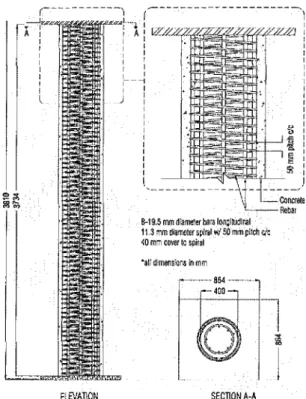
Fig. i-Dimensions and reinforcement details for column test specimens.
Reinforcing steel
Both the longitudinal and spiral reinforcement conformed to CSA Standard G30.l8, with minimum yield strengths of 400 MPa. The actual tested yield strengths of the reinforce-ment were 400 and 460 MPa for the spiral and longitudinal steels, respectively.
Casting, curing, and conditioning
The columns were placed vertically in a single lift, with concrete supplied by a local concrete plant. The concrete was rod-vibrated during each lift to ensure excellent consolidation. The columns were cured in a humidified plastic enclosure at 21 to 24°C and 100% relative humidity for 7 days, at which point the form work was removed. The columns were subsequently conditioned in the Structures Testing Lab at Queen's University, at ambient temperature and relative humidity for approximately 13 months prior to installation of the FRP wraps. SECllONA-A ',Ii dimensions inmm Gセcッョ」イ・ャ・ c·_-.'-,-Rellar B-19,5mm diameterbarslonCllUdlMI
11,3mmdiameterspiralwlSQ mmpitch ric
セッ mm cover 10 spilal ELEVATION
c--- ---)
(---
---·1 NNZNNNNZNNjセqセ I,.• I IA:
Ifi:
AI : : I : : I I I I I I 1 r I I r I : I I__セ I:
:
l
:
l ) I I I I I I I I I I I I I I I I I I I I I I l, --__ _ )FIRE TEST PROGRAM
Fire endurance criteria forfrpセキイ。ーー・、 columns
For the purposes of the current study, three fire endurance failure criteria, only one of which is currently recognized by ASTM E 119, have been defined. An FRP-wrapped column can be assumed to have failed if one of the three following criteria is met: 1) the column can no longer carry its full unfactored working (service) load; 2) the temperature at the FRP-concrete interface (the bond-line) exceeds theTgof the FRP polymer adhesive/matrix; or 3) the temperature at the outside surface of the FRP exceeds the ignition temperature of the FRP material.
The first of the aforementioned criterion is essentially the currently enforced ASTM E 119 fire endurance failure criterion for columns. The second and third criteria have both been suggested recently as potential failure criteria to be used in evaluating the fire endurance of FRP-wrapped columns for use in buildings. The rationale behind the second failure criterion is that the maintenance of the FRP temperature below the matrix Tgensures that the FRP will retain some structural effectiveness. The third criterion has been proposed to address concerns regarding the potential for increased flame spread and smoke generation when combustible FRP materials are used in external reinforcing applications. All three failure criteria are discussed in detail in subsequent sections.
based on conservative assumptions and is not founded in research. Furthermore, such a requirement is potentially restrictive when FRPs are contemplated for use in buildings. The engineering community often requires design recommen-dations developed based on the results of full-scale fire endurance tests (Munley and Dolan 2001) such as those presented in this paper.
Specimens
As part of the experimental program, two full-scale FRP-wrapped and insulated circular reinforced concrete columns were tested in the column furnace of the National Research Council of Canada (NRCC). Dimensions and reinforcement details for the columns were as given in Fig. 1. Both columns had a diameter ofセoo mm and an overall height of3810 mm. The columns were reinforced internally with eight 20 diameter deformed steel bars longitudinally, and a 10 mm-diameter deformed steel spiral with a center-to-center pitch of 50 mm. The concrete cover to the principal reinforcement
•Curing schedule 72 hours post-cure at 60 °C.
Fig. 2-Instrumentation for fire test specimens (at column midheight).
r-
EI Coating Mセlr-
Concrete MMLセセセ Thermocouples on Sleel Thermocouples in Concreleand InsulalJon Layers
ャイセM
It'6 ..
9.1718
12
3 456 7 8Property ASTMmethod Test value Design value
(1) (2) (3) (4)
Ultimate strength, MPa D3039 1351 1149
Elongation at break, % D 3039 1.4 ].4
Tensile modulus, GPa D3039 95.2 80.7
Nominal thickness, mm D3039 0.76 0.76
Matrix Tg•oC' D4065 93
-for protection of both columns. The system is a two-component active/passive fire protection system. One component of the insulation is a modified cementitious vermiculite/gypsum plaster (VO), and the other, a surface coating, is an intumescent epoxy paint (EI).
For the columns tested herein, the VO insulation was fIrst spray-applied over a galvanized steel plastering lath which was anchored to the outer surlace of the FRP-wrapped columns using concrete anchors. The lath, which is not an essential component of the fIre insulation system, was incorporated in these initial tests to provide a mechanical anchorage between the VO and the FRP and ensure that the insulation would remain intact for the duration of the tests. The lath was completely encased in VO insulation during the installation process. Column 1 was protected with approximately 57 mm, and Column 2 with approximately 32 rom. The EI epoxy surface coating was then hand-applied using a trowel to nominal thick-nesses of 0,25 and 0.56 mm on Columns 1 and 2, respectively. Details of the insulation system are shown in Fig. 2.
Instrumentation
Both columns were extensively instrumented with thermo-couples at their midheight, as shown in Fig. 2. In addition to the sensors installed within the columns, load and stroke were monitored by the load frame throughout the tests, and
Table1-Typical manufacturer-specified laminate properties for unidirectional carbon/epoxy FRP system
Fiber-reinforced polymer wraps
Because of their superior retention of mechanical properties at elevated temperatures (Bisby et al. 2002; Bisby 2003;
Blontrock et al. 1999), carbon FRP was chosen as opposed to glass or aramid FRP as the wrap material for both colWlllls. The FRP wrap design consisted of a single layer of a unidirec-tional carbon/epoxy FRP system with a 300 mm overlap in the circumferential direction and a 25 mm overlap in the vertical direction. The overlap lengths were chosen based on the industry partner's specifications, and their effects on the confined behavior of FRP-wrapped columns are not known (although they are not considered to be significant factors). The adhesive/matrix consisted of an epoxy.
The single-layer FRP wrap design was selected because it resulted in a theoretical ultimate load-capacity increase of approximately 53% based on ACI 440.2R-02 design guide-lines, and of approximately 26% based on the ISIS (2001) guidelines. The larger theoretical increases in axial load capacity that could result from higher confinement ratios (with two layers of FRP, for instance) were thought to be unrealistic, and would not currently be practical in a design situation. Manufacturer-specified properties of the FRP and adhesive/matrix materials are given in Table 1.
Insulation schemes
A detailed review of the literature on the high-temperature behavior ofFRP materials (Bisby 2003) indicated that rapid and severe deterioration of the mechanical and bond properties of FRP materials can be expected at only moderately increased temperatures, and highlighted the need for thermal insulation of FRP wraps. Until now, the approach used in the industry to provide insulation for FRP wraps has been to apply an intumescent paint to their exterior. In the event of a fire, the intumescent paint releases gases, foams, and expands to many times its original thickness, thereby fonning an insulating char that protects the FRP from the thermal insult of the fire.
The primary shortcoming of intumescent systems for fire protection of FRP wraps is that the activation temperature (the temperature at which expansion and charring of the intumescent coating begins) for commonly available intumescent coatings is typically in the range of 200 to 300°C, substantially higher than theTgof most FRP matrix polymers (matrixes Tgare typically between 65 to 150°C [ACI Committee 440 2002]). As a result, the mechanical properties of FRP wraps and/or the bond between the FRP and the substrate concrete are likely to be lost or seriously deteriorated before the onset of the intumescent reaction.
To improve the behavior of intumescent fire protection systems for use with
:FRP
wraps, it was hypothesized that the addition of a secondary passive layer of insulation between the FRP and the intumescent coating would improve the fire endurance substantially. The rationale for this addition was that the intermediate layer, which would ideally consist of a passive layer of a highly insulating (low thennal conductivity and high heat capacity) and thermally inert material, would maintain the temperature of the FRP well below its T up until the onset of intumescence. After activation otthe intumescent coating, the significant thermal insulation provided by the intermediate insulation,illセオiiャ「ゥョ。エゥッョ with the intumescent char, would provide fire protection for the FRP for a substantial period of time.With the aforementioned rationale in mind, a recently developed and innovative fire insulation system was selected
furnace temperatures were continuously monitored at eight different locations within the test chamher.
Test procedures
Both columns were tested hy exposing them to heat in the column furnace at NRCC, which was huilt specifically for testing loaded full-scale columns under exposure to fire. The furnace, which is unique in North America, can reproduce the temperature, load, and heat transfer conditions to which a member might be exposed during a building fire. A detailed description of the test furnace is provided by Lie (1980).
The tests were carried out with both ends of the columns fixed against rotation and horizontal translation (a fixed-end condition). A concentric sustained axial load of 2515 kN was applied to both columns during fire exposure in accordance with ASTME119 specifications. ASTME 119 states that, throughout a fire endurance test, a column shall be exposed to fire on all sides and shall be loaded in such a manner as to develop, as nearly as practicable, the working (service) stress contemplated by the design. In conventional cases (that is, for steel-reinforced concrete or structural steel columns), the sustained fire test load is determined by calculating the ultimate design strengtb of the member in question and, assuming some ratio of dead-to-live load (typically between 0.25:1 and 3:1), back-calculating the service load. A complication that arises for FRP-wrapped columns is considerable uncertainty as to what the design load capacity of the column should be because various design recommen-dations are currently available for FRP-wrapped columns. Current design recommendations (ISIS 2001; ACI Committee 440 2002) yield substantially different design strengths for FRP-wrapped columns, and a judgment call must therefore be made as to which set of recommendations to follow. In the present study, the design strength was calcu-lated according to ISIS (200 I), and the service loads were back-calculated from this value assuming a dead-to-live load ratio of I: I, and using load factors of 1.5 forlive load and 1.25 for dead load (Canadian Standards Association 1994).Ifthe ACI 440.2R-02 design guidelines were used in combination with load factors of 1.4 and 1.7 for dead and live loads respec-tively, tllis would result ill
a
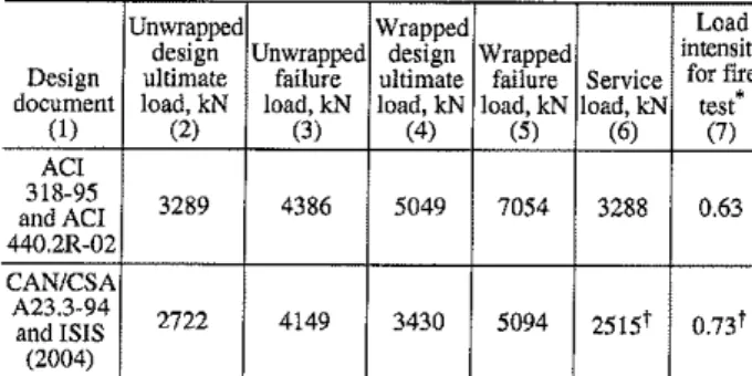
,ervico luad uf 3288 kN.Table 2 provides a comparison of results of load calculations for the columns with respect to predicted failure load, ultimate design load, and service load for the FRP-wrapped and unwrapped cases using the ACI and ISIS design guidelines. The load was applied to the columns for approximately 45 minutes before the start of the fire endurance tests, and was maintained at a constant value for the first 5 hours of fire Table 2-Load comparison for FRP-wrapped and unwrapped cases at ambient conditions
Unwrapped Wrapped Load
design Unwrapped design Wrapped intensity Design ultimate failure ultimate failure Service for fIre
•
document load, kN load, kN load, kN load,kN load, kN test(1) (2) (3) (4) (5) (6) (7) ACI 318-95 3289 4386 5049 7054 3288 0.63 and ACI 440.2R-02 CAN/CSA A23.3-94 2722 4149 3430 5094 2515! 0.73! and ISIS (2004)
Load mtensltyISratIO of service load (fire test load) to ultimate deSign load. tSustained load chosen for application during fire test.
886
exposure. After 5 hours, the applied load was gradually increased until failure occurred in an effort to obtain information that could be used to validate the numerical models, described as follows.
The fire exposure for the columns was simulated by controlling the average temperature in the furnace such that it followed, as closely as possible, the standard fire time-temperature curve of ULC SIOI (Canadian Standards Association 1989), which is equivalent to ASTM E 119.
NUMERICAL MODEL
Because full-scale fire endurance tests are time-consuming and expensive, a numerical model was developed by the authors snch that, once validated by relatively few laboratory tests, it could be used to conduct parametric studies and investigate the effects of a number of parameters on the fire endurance of FRP-wrapped reinforced concrete columns. The specifics of the numerical model have been presented in a previous paper (Bisby 2003), so only a general overview is provided herein.
The model was developed using procedures and method-ologies similar to those used previously by researchers at NRCC for modeling the fire endurance of conventionally reinforced concrete columns (Kodur and Lie 1997; Lie 1992; Lie and CelikkoI1991). The approach consists of a coupled heat transfer/load capacity analysis that has been programmed for a computer. The first portion of analysis uses an explicit finite-difference heat transfer formulation, based on an elemental energy balance, to calculate the temperatures inside a radially discretized column when it is subjected to a standard time-temperature curve. The heat transfer analysis accounts for the variation in thermal properties of the materials involved with temperature, and assumes that the column is infinitely long and the effect of internal rein-forcing steel on heat transfer within the member can be neglected. The current model ignores the presence of the intumescent (EI) fire protection because the effects of the intumescent coating were relatively short-lived during the fIre tests reported herein and are not thought to be significant. The second portion of the analysis calculates the load capacity of the member during fire, based on strain compatibility and equilibrium of forces, and on the known distribution of internal temperatures ohtained during the heat transfer analysis. The numerical model is unique in that it accounts for the confining effect of an FRP wrap in calculating ti,e load capacity and elongation of a reinforced concrete column during fire, with failure occurring by buckling or by crushing of the concrete. The model incorporates a modified version of the iterative FRP confinement procedure developed by Spoelstra and Monti (1999), where the procedure has been modified to account for the deterioration in mechanical properties (and thermal expansion) of concrete, steel, and FRP with increasing temperature. The model does not currently account for the confining effect of the internal steel spiral. The output consists of the distribution ofternperatures throughout the column cross section during exposure to fire, the variation in load capacity of the column, and the axial elongation of the column under a user-specified sustained load. A more complete description of the model is presented by Bisby (2003).
FIRE TEST RESULTS
Both columns behaved similarly during fire endurance tests, and both achieved greater than a 5-hour fire endurance ACI Structural Journal/November-December 2005
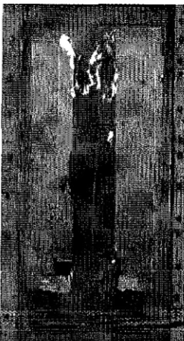
rating according to ASTM E 119 guidelines. The unique two-component fire insulation performed well and remained intact for the duration of the tests. Failure of the columns occurred near the column midheight after 5.5 hours of exposure to fire, and failure was sudden and explosive. Failure appeared to occur by a combined buckling/crushing failure accompanied by violent spalling of the concrete cover and insulation. A failed column is shown in Fig. 3. It is important to recognize that failure of the columns occurred after prolonged exposure to fire, and only when the applied load on the columns was increased to approximately 180% of the required service load. The load was increased to determine the ultimate strength of the members at the end of the tests, The observed failure load of the columns after exposure to the standard fire for longer than 5 hours was slightly more than the predicted strength of the unwrapped columns calculated using either the ACI 318 (ACI Committee 318 1995) or CAN/CSA A23.3-94 (CSA 1994) codes without reduction factors, Temperatures
Figure 4 shows temperature profiles recorded at several instructive locations in Column I during exposure to fire. Included in Fig. 4 are thermal profiles showing the standard fire curve (furnace temperature) along with the temperatures at the outside surface of the VG insulation, the outside surface of the FRP wrap, and the outside surface of the concrete.
The temperature at the surface of the VG insulation rose rapidly within the first 30 minutes of fire exposure, following the furnace temperature profile with a slight lag, to temperatures in excess of 600°C. It is interesting to consider that an unprotected FRP wrap would deteriorate completely at these temperatures. The VG insulation surface temperature then began to level off as the slope of the standard fire curve decreased.
Examination of the thermal profile at the surface of the FRP wrap in Fig. 4 and 5 indicates that good thermal protection for both columns was provided by the fire insulation system. The temperatures recorded at this location increased within the first hour of exposure, to temperatures between 95 and
100°C. The FRP surface temperature, however, then leveled off near 100°C for approximately 3 hours before increasing again beyond 4 hours of fire exposure. This plateau, near 100°C, is associated with the unique thermal properties of the fire insulation materials and is due to the release of both free and chemically combined water at temperatures close to 100 DC. In combination with the very low thermal conductivity of the intermediate insulation, this moisture loss maintains the wrap temperature near 100 DC for approximately 3 hours, and results in an insulation system that is extremely effective at maintaining low temperatures in the FRP wrap.
The thermal insulating ability of the FRP wrap can be approximately ascertained by examining the temperatures at the surface of the concrete in comparison with those at the surface of the FRP. Although FRPs generally have low thermal conductivities in the transverse direction (Bisby, Greene, and Kodur 2001), they are typically very thin in comparison with the insulation or the underlying concrete column. The data presented in Fig. 4 show that the concrete surface temperature closely followed the FRP surface temperature for Column 1. The magnitude of the temperature differential across the FRP increased late in the fire endurance test-behavior that was observed in both fire tests and appeared to be due to changing thermal properties of the wrap at elevated temperature, likely resulting from partial combustion of the FRP polymer matrix.
Temperatures recorded in the concrete and at the level of the internal reinforcing steel were observed to remain less
Standard Fire Curve • _,._ .. - .. - .•-. \.
_
..
_
..
_
..
-
..
_.
-セ...
....
- - VGlnsulallon Surface ... FRP Surface - - - - Concrele Surface • Test Data • Modal Predictions Time (min)Fig. 5-Predicted and observed temperatures at various locations in Column2during fire endurance testing(32mm insulation). 300 300 240 160 120 60 60 1000
E
800 セ.a
600 セ Q) a. E 400 セ 200a
a
Standard Fire Curva _"_' _ ..-.
\.
_..
-
..
-
..
_
..
-
..
-
..
_
..
",:' _ _'_ VG InSUlation Thicknessi
FRP Surface _ _- - : l : - - - - Concrale Surface I • Test Dala .. •mo、・NiNセセセセZセセセセセNZ
セセセセセ
....
" . -NセセNNNN Mセ⦅..
⦅セMセZZMM...
...--.,.-... セZZZ[[セNN--. セセ⦅
..
,»t:&lIIo...Mセ 120 180 240 Time (min)Fig. 4-Predieted and observed temperatures at various locations in Column 1 during fire endu ranee testing(57mm insulation).
Fig. 3-Column2 shown immediately after failure during fire testing.
than 120 'C for the full 5.5 hours fire exposure for Column 1. It should be noted that such modestly increased temperatures are not significant for concrete or conventional steel rein-forcement because there is no substantial loss in the strength of these materials up to temperatures of approximately 300 'C. Thus, it can be stated that Column I likely maintained its full unwrapped strength for the entire duration of fire exposure. This conclusion is supported by the observed ultimate failure load of the column, discussed as follows.
Figure 5 shows temperature profiles recorded at various locations within Column 2 during exposure to fire. Again, the temperature at the surface of the insulation followed the standard fire curve, as expected, although more closely in this case than for Column I. This can be attributed to uncertainty as to the exact location of the insulation surface thermocouples, which may have been slightly dislocated during installation of the insulation system. Thermal profiles recorded at the FRP and concrete surfaces were similar to those observed for Column I, with the exception that the 100°C temperature plateau was reached earlier and was considerably shorter in duration for Column 2. This can be attributed to the fact that Column 2 was protected with approximately half the thickness of fire insulation applied to Column I. Although significantly higher temperatures were experienced at the level of the FRP for Column 2, temperatures recorded in the concrete and internal reinforcing steel remained low (less than 200 'C in this case), and thus the column likely maintained its full unwrapped strength for the entire duration of fire exposure.
Axial deformation
Figure 6 shows the axial deformation of both columns recorded during fire exposures. Both columns displayed a very slight elongation under fire exposure as a consequence of very mild thermal expansion. The magnitude of the expansion was greater for Column 2, which experienced
,
I :
セ⦅Go[B[[BBセB]B]BGゥゥゥGZゥゥZZZZセZZセZZゥZZZセZZセZZGZBZBZBGZBZ
....
ZNZZZZZZZZZZZセZセセNZNセZZZセセZZZZセZLLセ
..
セ
w 2I '
I'
,o
セ - - - Column 2 Load Increased J... 'Column1
セ
-4 I"<
•
Test Data • Model PredIctionsI
,
-6 ...MMZBZBGBMNMNNNNN⦅セセMMZBZBGB⦅NNNNlNNNNNNNijo
60 120 180 240 300Time of Fire Exposure'(min)
Fig. 6-Predicted and observed axial deformations of Columns 1 and2during fire endurance testing.
slightly higher internal temperatures than Column 1 due to a lower thickness of insulation. The overall magnitude of the columns' expansion was small in comparison with their overall length, with a maximum observed elongation of less than approximately 0.025% of the original length (3810 mm). This can be attributed to the beneficial thermal insulation provided by the fire protection, which resulted in minimal temperature increases in the concrete and internal reinforcing steel.
Beyond 5 hours of fire exposure, both columns displayed a sudden and severe contraction, which can be attributed to increasing the applied load at 5 hours up until failure. Fire endurance
Table 3 provides fire endurance times for both columns based on the three potential fire endurance failure criteria outlined previously. As stated previously, both columns achieved fire endurances longer than 5 hours based on ASTM E 119 load capacity criterion (Criterion 1).
If the fire endurance of the columns is defined in terms of the time to reach the matrix Tg(which was approximately 93 °C for the FRP system discussed herein), then Columns I and 2 have fire endurances of 182 and 82 minutes, respectively. These times are less than the ones based on the structural fire endurance criterion (Criterion 1), and illustrate that it is indeed overly conservative to define fire endurance in terms of the matrixTg •
Based on failure Criterion 3, exceeding the ignition temperature of the FRP polymer matrix, both columns displayed fire endurances longer than 5 hours, and combustion of the FRP wrap does not appear to be a serious concern for either of the columns tested.
MODEL VALIDATION
The numerical model, described very briefly in a previous section and in detail by Bisby (2003), has been previously validated against data obtained from fire tests on unwrapped and uninsulated circnlar reinforced concrete columns (Bisby 2003). In the following discnssion, data obtained from the two fire endurance tests described herein are used to validate the model for the FRP-wrapped and insulated case.
Temperatures
Figure 4 and 5 show comparisons of experimental data and model predictions for temperatures at several locations for Columns 1 and 2, respectively. In Figure 4 and 5, the predicted temperatures at the FRP surface and concrete surface are essentially coincident. In both cases, the model predictions agree relatively well with the experimental data, and the model accurately captures the overall trends observed in the test data. The model does not, however, precisely capture the 100 'C temperature plateau observed in the test data at the surfaces of the FRP and the concrete. This Table 3-Experimentally observed and numerically predicted fire endurance
Fire endurance, minutes
vn
エィゥHャQイョHGセセL EIエィゥ」ォョcZゥャセL Criterion 1: load capacity Criterion 2; matrixT/
BNᆪセゥエcャェャjiiSL JIll:llliAゥセャャゥャゥオャャャエZャiijNjエZhエluiエZエNo. mm Inm Test Model Test Model Test Model
(1) (2) (3) (4) (5) (6) (7) (8) (9)
1 57 0.25 >300 >300 182 108 >300 >300
2 32 0.56 >300 >300 82 47 220 >300
·Taken at 93°C based on data supplied by manufacturer. tTaken as 450°C based on tests conducted by Bisby (2003).
- Applied Load - . - Predicted Capacity
Solid Lines: Column1 Dolled Lines: Column 2 120
- - - - Spiral Steel
100 ... Vertical Steel (Outside)
5
- - - - Vertical Steel (Inside)'<..,... 80 • Test Data セ • Model Predictions
.a
60 lI! セ E 40 セ 20 olNNッNNセMBGセセBBBBGセセBBBBBBセBGMMoMj」NNNッNNNNNNNセMLMLM ...o
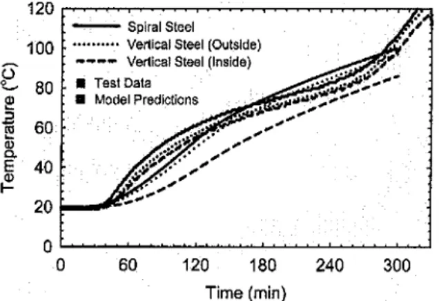
60 120 180 240 300 Time (min)Fig. 7-Predicted and observed temperatures at level of internal reinforcing steel for Column 1.
wrap remained effective in the later stages of the tests. The model predictions for failure load agree well with test observations even after 5.5 hours of exposure to the ASTM E 119 standard fire. Thus, it appears as though the model can accurately predict the failure load and structural fire endurance ofFRP-wrapped and insulated columns, although further tests are required to confirm this initial conclusion. Axial deformation
Figure 6 shows the measured and predicted axial defor-mations of Columns 1 and 2 as a functions of fire exposure time, assuming an applied axial load of 2515 kN, as was applied during the fire tests. The model tends to overpredict the expansion of both columns for the full length of fire exposure, Nonetheless, the largest difference between predicted and measured axial deformation is on the order of 1.5 mm, which is small in comparison to the overall length of the columns.
For the design of structures for fire safety, the model is conservative because larger axial deformations in fire would result in the development of larger induced deflections in a structure. Itis suspected that the discrepancy between the predicted and observed column deformations can be attributed primarily to short-term creep of the concrete at elevated temperatures in combination with some minor seating effects. Given the extremely small magnitude of the deformations, both predicted and observed, it is difficult to state conclusively whether the model is an adequate predictor of axial elongation for FRP-wrapped and insulated columns.
1000 4000
Z
3000 C "0 (\] .3 2000 120 180 240 300 360 Time (min)Fig. 8-Predicted load capacity and applied load during fire endurance tests for Columns 1 and 2.
can be explained by considering that the model does not explicitly account for the evaporation of moisture from the insulation at 100 °C, nor does it account for moisture movement within the insulation (which tends to cause moisture to move toward the center of the column, away from the heat source). The model accounts for moisture evaporation in the insulation by artificially increasing the specific heat of the insulation elements at temperatures near 100 °C, an approach that has been used successfully in the past. While capturing the 100 °C plateau is not critical for calculating the structural fire endurance of the FRP-wrapped columns, it could become important if fire endurance is defined in terms of the matrixTgbecauseTgis close to 100°C for many currently available FRP-wrap matrix materials. The model appears to overpredict the temperature at the surface of the
va
insulation early in the fire tests. This behavior can be attributed to the fact that the temperatures at the surface of theva
insulation are reduced by the action of the intumescent EI coating during the first 15to20 minutes of fire exposure, behavior which is not accounted for in the model but which is relatively short-lived and not thought to be significant for the overall fire endurance of the columns.Figure 5 also shows that the numerical model under-predicts the temperatures at the level of the FRP wrap beyond 80 minutes of fire exposure for Column 2. This discrepancy is thought to be due to the development of cracks in the insulation, which were observed to gradually appear and widen as the fire endurance tests progressed, and which could have allowed heat to penetrate more rapidly to the level of the FRP. Cracking of the insulation is not accounted for in the model.
Figure 7 shows predicted and observed temperatures at the level of the internal reinforcing steel for Column 1. The figure includes curves for temperatures recorded on the steel spirals and on the vertical reinforcing bars on the side of the bar closest to the fire (outside) and the side of the bar furthest from the fire (inside). Satisfactory agreement between test data and model predictions is evident, particularly given that the reinforcing steel temperature remained less than 100°C foethe duration of fire exposure. Similarly, good agreement between test data and model predictions was noted for Column 2 at the level of the internal reinforcing steel. Load capacity
The ability of the numerical model to predict the load-carrying capacity of FRP-wrapped columns during fire is an important consideration in its validation. Figure 8 shows the predicted load capacity of Columns I and 2 under exposure to fire, together with curves showing the applied load on both columns during tests. It is importanttorecognize that because the load capacity analysis approximates the bUCkling strength on the member, for the numerical model to function properly, an initial eccentricity is required as input. In the development of Fig. 8, an initial eccentricity of 27 mm was chosen, in accordance with Section 10.12.3.2 of ACI 318-95. Although the analysis is also capable of predicting the axial crushing strength of the columns during fire, the huck ling-type failure governs the design for column lengths that would generally be encountered in practice.
As expected, the model predicts that the axial load capacity of the columns deteriorates only slightly during exposure to fire. This can be attributed to the beneficial thermal protection provided by the insulation, primarily to the concrete and reinforcing steel.Itremains unknown astowhether the
Fig. 9-Predictedfire endurance curves for various column configurations.
fail at 100 minutes This highlights the need for supplemental
fire insulation to achieve similar fire endurance for the
FRP-wrapped column. Indeed, by insulating the column with 32 mm of the insulation system described previously, the fire endurance increases to longer than 6 hours. Thus, the predicted fire endurance for the FRP-wrapped and insulated column becomes greater than for the nnwrapped column, even though the wrap likely becomes ineffective during fire exposure.
ACKNOWLEDGMENTS
The authors are members of the Intelligent Sensing for Innovative Structures Network (ISIS Canada) and wish to acknowledge the support of the Networks of Centres of Excellence Program of the Government of Canada and the Natural Sciences and Engineering Research Council of Canada. The authors would also like to acknowledge the National Research Council1)[Canada, Queen's University, Kingston, Ontario, Canada, ann Fylc Co. LLC. San Diego, CaUf.
CONCLUSIONS
Based on the results of full-scale fire endurance tests on circular FRP-wrapped and insulated reinforced concrete
columns, the following conclusions can be drawn:
1. The insulation system described herein is an effective
protection system to maintain the overall load-carrying
capacity of FRP-wrapped reinforced concrete columns during fire. The insulation remained intact for more than
5 hours of exposure to the ASTM E 119 fire;
2. Itis possible, with the requisite thickness of the fire
insulation, to maintain the temperature of an FRP wrap
below 100 'C for up to 4 hours during exposure to the standard fire;
3. Both of the FRP-wrapped and protected reinforced
concrete columns described herein achieved fire endurance
ratings in excess of 5 hours according to ASTM E 119, with service loads calculated using the ISIS Canada design guide-lines (ISIS 2001); and
The predictions of a numerical fire endurance model,
developed previously by Bisby (2003) to predict the heat transfer behavior and axial load capacity of FRP-wrapped
and insulated reinforced concrete columns during exposure
to fire, were compared with data obtained from the fire tests
discussed herein. The following conclusions can be drawn on the basis of that comparison:
4. The numerical model can adequately predict tempera-tures within circular FRP-wrapped and insulated reinforced
concrete columns during exposure to fire; and
5. The numerical model appears to be capable of predicting the load capacity and structural fire endurance of
FRP-wrapped and insulated reinforced concrete columns.
Both the fire endurance tests and the numerical model indicate that the fire endurance of FRP-wrapped concrete members should be determined using a holistic approach, with the goals of fire-safety engineering clearly in mind. Thus, structural fire endurance should be defined on the basis of load-carrying capacity, rather than other possible criteria such as the T of the FRP polymer matrix/adhesive or the effectiveness or the FRP wrap. FRP-wrapped columns
treated in this manner are capable of achieving required fire endurance, provided that insulation is applied to the exterior
of the FRP wrap.
REFERENCES
ACI Committee 440, 2002, "Guide for the Design and Construction of Externally Bonded FRP Systems for Strengthening Concrete Structures CACI 440.2R·02)," American Concrete Institute, Farmington Hills, Mich., 45pp. 360 300 180 240 Time (min) 120 60 Unwrapped Wrapped _._._.- Wrapped-Insulated oeNNNNNNNセNNNNNNjNiNNNNNNM __セNNNNNNjZNNNNNNNNセNNNNNNNNNNj o ' 0 0 0 , - - - ,
3
P,-'- - _._.- -'-'-'- -'-'-'- -._.- - -.-.
:z:
4000 .... '0 セBGBセ
3000 '''''''''''''''''''''''''''''''.§
·2000f----r---=-""'''f'o'''.''''".'C''''C"''''-.-''''-...
-1
Nセ'tl
1000as
DISCUSSIONOne interesting question that arises in any discussion of
the fire tests described in this paper is whether the FRP wrap remained effective for a significant period of time during fire. Unfortunately, it is not possibleto state conclusively
when, orif,the FRP wrap became ineffective as a confining
mechanism for the concrete. It is known that FRP confinement
is only significantly activated at stress levels close to the
unconfined ultimate strength of the concrete. The sustained
service load applied to the columns in the current study (2515 kN) would result in a concrete stress of only approximately 17 Ml'a during fire, significantly less than the ultimate strength of the unconfined concrete. Hence, no noticeable change in column behavior would be expected
due to loss of the confining action of the FRP wrap. Itis important to recognize that the superior fire behavior
of the FRP- wrapped and insulated columns described herein
is due primarily to the thermal protection provided the insulation system to the concrete and reinforcing steel, and it
is unlikely that the wrap remained effective toward the end of the tests. Itcould thus be argued that an unwrapped but insulated column would perform similarly in fire to an
equivalent FRP wrapped and insulated column. However,
columns are confined with FRP to increase their axial load capacity at ambient conditions, not to increase their structural fire endurance. Therefore, supplemental fire insulation is required in these cases to ensure that the overall column can safely carry the increased service loads in the event of fire. This is becauseftresafety engineering is concerned primarily
with protection against structural collapse and loss of life during fire, and so it is the overall load-carrying capacity of the FRP-wrapped columns that is important, not the main-tenance of the FRP confmement.
To illustrate the aforementioned points, Fig. 9 shows the variation in load capacity of an FRP-wrapped aod insulated column (Column 2) as predicted by the numerical model, along with an equivalent unwrapped column and FRP-wrapped but uninsulated column. Also included in Fig. 9 are
horizontal lines showing the calculated service loads on
these columns according to ACI 318 and ACI 440 (assuming a live to dead load ratio of 1.0). The initial strength of the
wrapped columns is only セャゥァィエQケ increased becaust: Lht:
columns are assumed to fail by buckling, which is the critical
failure mode during fire, andFRP confinement cannot be
expected to significantly increase the columns' buckling strength.
The unwrapped column has a predicted fire endurance of about 245 minutes, whereas the wrapped but uninsulated column, which has an increased service load, is predicted to
ACI Committee 318, 1995, "Building Code Requirements for Structural Concrete (ACI 318-95) and Commentary (318R·95)," American Concrete Institute, Farmington Hills, Mich., 369 pp.
ASTM E 119-00a, "Standard Methods of Fire lest of Building Construc-tion and Materials," ASTM InternaConstruc-tional, West Conshohocken, Pa., 2000,
21 pp.
Bisby, L.A, 2003, "Fire Behaviour of Fibre-Reinforced Polymer (FRP) Reinforced or Confined Concrete," PhD thesis, Department of Civil Engineering, Queen's University, Kingston, Ontario, Canada, 371 pp.
Bisby, L. A; Green, M.F.; and Kodur, V.K,R., 2001, "Fire Behaviour of FRP-Wrapped Reinforced Concrete Columns," Structural Faults and
Repair-200], London, July. (CD-ROM)
Bisby, L. A; Williams, B.K,;Green, M.F.;and Kodur,V.K. R., 2002, "Studies on the Fire Behaviour of FRP Reinforced and/or Strengthened Concrete Members," Proceedings of the 2nd International Conference on
the Durability of Composites for Construction, Montreal, Quebec, Canada, May,pp.405-417.
Blontrock, H.; Taerwe, L.; and Matthys, S., 1999, "Properties of Fiber Reinforced Plastics at Elevated Temperatures with Regard to Fire Resistance of Reinforced Concrete Members," Fourth International Symposium on Fiber
Reinforced Polymer Reinforcement for Reinforced Concrete Structures,
SP-1S8, C. W. Dolan, S. H. RizkalJa, and A Nanni, eds., American Concrete Institute, Farmington Hills, Mich., pp. 43-54.
Blontrock, H.; Taerwe, L.; and Vandevelde, P., 2000, "Fire Tests on Concrete Beams Strengthened with Fibre Composite Laminates," Third
PhD Symposium, Vienna, 10 pp.
Blontrock, H.; Taerwe,L.; and Vandevelde, P., 2001, "Fire Testing of Concrete Slabs Strengthened with Fibre Composite Laminates," Proceedings
ofthe Fifth Annual Symposium on Fibre-Reinforced·Plastic Reinforcement for Concrete Structures (FRPRCS-5), Thomas Telford, London, pp. 547-556.
CAN/CSAG30.18, 1992, ''Billet·Steel Bars for Concrete Reinforcement," Canadian Standards Association, Mississauga, Ontario, Canada, 18 pp.
CANIULC, 1989, "Standard Methods of Fire Endurance Tests of Building Construction and Materials," CAN/ULC·SIOl·M89, Underwriters' Laboratories of Canada, Scarborough, Ontario, Canada, 49 pp.
CSA, 1994, "Design of Concrete Structures (CAN/CSAA23.3-94)," Canadian Standards Association, Ottawa, Ontario, Canada, 220 pp.
ISIS, 2001, Strengthening Reinforced Concrete Structures with
Externally Bonded Fiber Reinforced Polymers, Intelligent Sensing for
Innovative Structures Canada, Winnipeg, Manitoba, Canada, 193 pp. Kodur, V.K. R, 1999, "Fire Resistance Requirements for FRP Structural Members," Proceedings ofthe Annual Conference of the Canadian Society
for Civil Engineering, Regina, Saskatchewan, Canada, pp. 83·95.
Kodur, V. K. R., and Baingo, D., 1998, "Fire Resistance of FRP Reinforced Concrete Slabs," IRC Internal Report No. 758, National Research Council of Canada, Ottawa, Ontario, Canada, 37 pp.
Kodur, V. K. R., and Lie,T. T., 1997, "Evaluation of the Fire Resistance of Rectangular Steel Columns Filled with Fibre-Reinforced Concrete,"
Canadian Journal of Civil Engineering, V. 24, No.3, pp. 339·349.
Lie, T. T., 1980, "New Facility to Detennine Fire Resistance of Columns,"
Canadian Journal olCivil Engineering, V. 7, pp. 551-558.
Lie,T. T., 1992, "Structural Fire Protection," Manuals and Reports on
Engineering Practice No. 78, ASCE, New York, 241 pp.
Lie, T. T, and Celikkol, B., 1991, "Method to Calculate the Fire Resistance of Circular Reinforced Concrete Columns," ACIm。エ・イゥ。lセ Journal, V. 88,
No.1, Jan.-Feb., pp. 84-91.
Munley, E., and Dolan, C. W., 2001, "What is the Value of it All?"
Proceedings of the Fifth Annual Symposium on Fibre-Reinforced·Plastic Reinforcement for Concrete Structures (FRPRCS-5), Thomas Telford,
London, pp. 585-592.
Sorathia, U.; Dapp, T.; and Beck, C., 1992, "Fire Performance of Composites," Materials Engineering, Sept., pp. 10-12.
Spoelstra, M. R., and Monti, G., 1999, "FRP-Confined Concrete Model," Journal of Composites for Construction, V. 3, No.3, pp. 143-150.