Publisher’s version / Version de l'éditeur:
Vous avez des questions? Nous pouvons vous aider. Pour communiquer directement avec un auteur, consultez
la première page de la revue dans laquelle son article a été publié afin de trouver ses coordonnées. Si vous n’arrivez pas à les repérer, communiquez avec nous à PublicationsArchive-ArchivesPublications@nrc-cnrc.gc.ca.
Questions? Contact the NRC Publications Archive team at
PublicationsArchive-ArchivesPublications@nrc-cnrc.gc.ca. If you wish to email the authors directly, please see the first page of the publication for their contact information.
https://publications-cnrc.canada.ca/fra/droits
L’accès à ce site Web et l’utilisation de son contenu sont assujettis aux conditions présentées dans le site LISEZ CES CONDITIONS ATTENTIVEMENT AVANT D’UTILISER CE SITE WEB.
Stereoscopic Display and Applications XVII Conference, Part of: IS&T/SPIE 18th
Annual Symposium on Electronic Imaging Science and Technology
[Proceedings], 2006
READ THESE TERMS AND CONDITIONS CAREFULLY BEFORE USING THIS WEBSITE.
https://nrc-publications.canada.ca/eng/copyright
NRC Publications Archive Record / Notice des Archives des publications du CNRC :
https://nrc-publications.canada.ca/eng/view/object/?id=b89ac7c2-9685-42d7-91d3-3149d76803b3
https://publications-cnrc.canada.ca/fra/voir/objet/?id=b89ac7c2-9685-42d7-91d3-3149d76803b3
NRC Publications Archive
Archives des publications du CNRC
This publication could be one of several versions: author’s original, accepted manuscript or the publisher’s version. / La version de cette publication peut être l’une des suivantes : la version prépublication de l’auteur, la version acceptée du manuscrit ou la version de l’éditeur.
Access and use of this website and the material on it are subject to the Terms and Conditions set forth at
High-Resolution Insets in Projector-Based Display: Principle and
Techniques
National Research Council Canada Institute for Information Technology Conseil national de recherches Canada Institut de technologie de l'information
High-Resolution Insets in Projector-Based
Display: Principle and Techniques *
Godin, G., Massicotte, P., and Borgeat, L.
January 2006
* published at the Stereoscopic Display and Applications XVII Conference, Part of: IS&T/SPIE 18th Annual Symposium on Electronic Imaging Science and Technology. January 15-19, 2006. San Jose, California, USA. NRC 48460.
Copyright 2006 by
National Research Council of Canada
Permission is granted to quote short excerpts and to reproduce figures and tables from this report, provided that the source of such material is fully acknowledged.
High-resolution insets in projector-based
stereoscopic displays: principles and techniques
Guy Godin, Philippe Massicotte and Louis Borgeat
Visual Information Technology Group
National Research Council of Canada
Ottawa, Ontario, Canada
ABSTRACT
We propose a dual-resolution foveated stereoscopic display built from commodity projectors and computers. The technique is aimed at improving the visibility of fine details of 3D models in computer-generated imagery: it projects a high-resolution stereoscopic inset (or fovea, by analogy with biological vision) that is registered in image space with the overall stereoscopic display. A specific issue that must be addressed is the perceptual conflict between the apparent depth of the natural boundary of the projected inset (visible due to changes in color, brightness, and resolution) and that of the underlying scene being displayed. We solve this problem by assigning points to be displayed in either the low resolution display or the inset in a perceptually consistent manner. The computations are performed as a post-processing, are independent of the complexity of the model, and are guaranteed to yield a correct stereoscopic view. The system can accommodate approximately aligned projectors, through image warping applied as part of the rendering pipeline. The method for boundary adjustment is discussed along with implementation details and applications of the technique for the visualization of highly detailed 3-D models of environments and sites.
Keywords: Dual-resolution display, foveated display, projector-based virtual reality, image warping.
1. INTRODUCTION
Projector-based stereoscopic wall displays are becoming the main approach for experiencing virtual reality. While the complexity of the models and the graphics power of commodity computer continue to increase, most of these displays still provide levels of image resolution that have remained almost unchanged for the last decade. In the particular case of wall-type displays, screen pixel size typically reaches several millimeters. This limitation is likely to become an issue as virtual environment displays become increasingly used for exploring models with a high level of details in geometry and texture, such as the ones created using 3-D laser range imaging and image-based techniques. Increasing the actual visual resolution of a display can be achieved by combining several units into a seamless unified display. A number of large-scale, high-resolution tiled monoscopic displays based on off-the-shelf components have been developed in the field of scientific visualization (e.g. Refs. 1, 2): these displays use an array of projectors that are aligned using either rigid mechanical setups or image warping techniques,3
providing a surface with an almost uniform pixel density. Resolutions of tens of millions of pixels are typically obtained. Similar tiled configurations have also been proposed for stereoscopic displays.4, 5
An alternate approach for increasing the apparent resolution of a display makes use of small, high-resolution insets within a larger, lower-resolution field of view. Apart from their resolution (and possibly other appearance factors such as color or brightness), the images in the low and high resolution areas appear as a unified display to the user. Such high-resolution inset methods are commonplace in flight simulators and head-mounted displays6–9; in a hybrid technique,10 a dual-resolution view is presented to the user with the combination of a head-mounted
display and projected background images at a coarser resolution. When the location of the inset in the visual field is displaced under gaze tracking control, these methods can yield an impression of increased resolution over the entire field of view for a single-user system, due to the spatially varying resolution of the human eye.
In dual-resolution displays, the high-resolution inset image is often referred to as the fovea, and the lower resolution surrounding image as the periphery, by analogy with the biological visual system. We will adopt this
terminology in the remainder of the paper, even when the display is not gaze-contingent. Digital projectors have considerably simplified the design and construction of such dual-resolution (or foveated) displays by alleviating the need for complex electronic and optical designs: in the “focus+context” display system,11 a high-resolution
LCD panel display is surrounded by a very large screen on which a lower resolution image is projected; a pair of projectors is used in the Escritoire project12 to create a desktop that incorporates a high-resolution area
for improved document viewing. A high-resolution inset was also shown as one of the operating modes of the PixelFlex system.13 Issues of appearance matching and screen irregularity in a two-projector monoscopic
foveated display are addressed in Ref. 14. These systems are not gaze-contingent, as they are often targeted to multi-viewer usage.
We recently introduced a stereoscopic version of projector-based foveated displays.15–17 Our system is aimed
specifically at highly detailed models of virtual environments: as with monoscopic foveated displays, it adds a high-resolution inset, or fovea, within a larger, coarser resolution display, while appearing as a unified image. In extending the approach to stereo, we identified a specific issue not present in monoscopic foveated displays: the visible boundary between the high-resolution inset and the low-resolution periphery creates a stereoscopic depth cue with a disparity which, in general, does not match that of the underlying scene. This creates a competition between two perceived depth layers. The effect is particularly strong when virtual objects are located in front of the screen. We proposed a first solution where the apparent position of the boundaries between inset and periphery is moved (by drawing a black region in the inset and replacing this portion of the display by the low-resolution image) until it lies over corresponding points of the scene. These matching points can be found explicitly because the scene geometry is known. The proposed method reduces the computational cost of boundary matching by using the depth buffer in each view as a proxy for the visible part of the scene.16 We
later proposed a second solution, based on spatial partitioning, which is better adapted to the newer generations of fast graphics cards,17 and requires a constant and lower amount of additional computations.
This paper provides a description of the key principles behind the foveated stereoscopic display, with an emphasis on implementation techniques and design aspects. The solution is presented for projectors that are only approximately aligned, thus requiring that each image be warped to match a common screen-centered coordinate system. The warping is applied as part of the rendering pass, thus adding no computational or rendering cost and avoiding image-level interpolation. We then review the depth perception problem at the boundary and outline the solution that we have proposed. In the context of large virtual models, the high cost of rendering a frame precludes any technique requiring more than one rendering pass or even geometric computations on the scene model itself. The method adds a very low computational cost, in the form of a post-processing that is independent of the complexity of the scene model. We also propose to use a variant of the technique in order to partially reduce the problem of stereoscopic frame violation around the periphery display. We finally discuss some design issues, particularly with regards to projector brightness and performance, and the application context of our display system.
•
•
left right
Figure 1.Screen photograph of the foveated stereoscopic display, with each eye’s view separated (the images are normally superimposed, with opposing polarizations). This printed stereo pair is viewable in 3-D using “parallel eyes” sighting.
2. SYSTEM OVERVIEW
Figure 1 shows a screen photograph of our display, viewable as a stereo pair. The brighter inset area contains the same number of pixels as the surrounding image (1024 × 768). The image is viewed on a vertical flat screen measuring 3m by 2.3m, thus a viewer standing at 1.5m (for a 90◦ horizontal field of view) would see 3mm
pixels, subtending a visual angle of about 6.8 arcmin in the center of the screen. The inset projection area is approximately 1m wide, yielding a resolution of 2.3 arcmin, which still does not match the limit of visual acuity, but provides a significantly enhanced experience of the virtual world.
Our system is built from off-the-shelf hardware components. The display uses four DMD projectors, arranged in two pairs of periphery and fovea projectors, for the left and right eyes. Circular polarization is used for eye separation, with a polarization-preserving rear projection screen. The image for each projector is generated by a dedicated PC; the four computers share copies of the 3-D model to be rendered, and are synchronized through a local network. Details of the system architecture are found in Ref. 18. In such a multi-node implementation, one must emphasize the importance of synchronization, particularly between images within the same eye, since delays can cause visible image tearing. Although we used two pairs of projectors to generate the left and right images, the same concept can be implemented using only two time-multiplexed (or ”active”) stereo projectors. Newer PC architecture and graphics cards will allow the integration of the display system in two or even only one computer.
3. PROJECTION GEOMETRY
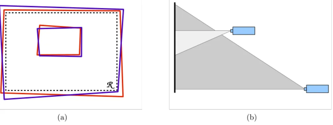
One important feature of our system is its ability to handle approximately aligned projectors. This is particularly advantageous when dealing with a four projector passive stereo system. This capability not only helps to avoid the tedious precise mechanical alignment of four overlapping projectors, but may prove absolutely necessary in some cases since the physical arrangement of projectors is constrained by the need to keep the foveal projectors outside of the light path of the periphery projectors. The only requirement is that the left and right projector images overlap on the screen, for both the periphery and fovea, and that the fovea be included within the periphery (Fig. 2). Creating a unified stereoscopic display requires that the images be transformed so that the fovea is aligned with the periphery for each eye view, and that the left- and right-eye composite images are properly adjusted for stereoscopic viewing. We define a reference rectangular area R on the screen; there are no a priori restrictions on the rectangle, but it is convenient to place it either at the physical boundary of the screen i.e. so that it is included within the intersection of the left and right periphery projectors, or, if the projected images does not cover the entire physical screen, as the bounding box of projector footprints.
We then construct the virtual projection matrices for each eye, defined by the viewer’s left and right eye positions with regards to the screen, eL and eR, and the reference rectangular area on the screen. We ensure
that the two skewed perspective matrices PLand PRshare common near and far clipping planes. These matrices
are the same as the ones commonly used in most stereoscopic applications. The matrices corresponding to these projections are of the form given by the glFrustum function in OpenGL.19
If we assume a pinhole projection model for the projectors, and since the screen is flat, the positions in the images fed to the projector and their positions on the screen are related by a 3 × 3 matrix H called homography, or collineation.20 The coordinates within the reference rectangle R and in the projector image are scaled to the interval [−1, 1] along x and y. A given screen position xscorresponds to the projector image location xp on
the screen according to the equation xp ∼= Hxs, with xp and xsexpressed as homogeneous coordinates and ∼=
denoting equality up to a scale factor. The homography can be estimated by computer vision methods, by manual pointing at targets, or a combination of the two. Four screen-to-projector homographies (HpL, HpR, Hf L, Hf R)
need to be determined (only three if one of the projector images is assumed to coincide with the reference rectangle). A recent survey3discusses such techniques in the context of tiled displays.
Once the desired image transformations are known, one technique for the correct alignment of images on the screen is to render them in each node as they should appear on the screen, inside the bounding box aligned to the reference rectangle, and then to read back the image, apply the homography and feed it to the projector. This two-pass approach, used for example in Ref. 12, has the advantage of being directly applicable to arbitrary display contents, including existing applications and user interface elements. However it requires frame buffer read-back
(a) (b)
Figure 2. Projection geometry: (a) the footprints of the four projectors need only be roughly aligned, with overlap between left and right images in both periphery and fovea; (b) fovea projectors must not create shadow in the light path of the periphery projectors.
and image resampling, which may affect speed and image quality. Current off-the-shelf digital projectors can also perform this warping from the source image, but this obviously restricts the area of high-resolution inset to a subset of the projector’s footprint. In our case, the entire contents of the screen will be generated by a 3-D graphics application, thus allowing the application of the homography as part of the 3-D rendering pass, at no additional computational cost, and without pixel-level resampling.21 Our method17differs from earlier ones by
improving the depth buffer usage and enforcing identical clipping planes.
Within the general OpenGL rendering pipeline, the 4 × 4 projection matrix P and model-view matrix M transform the scene geometry into screen coordinates and a depth value. A point xw = (x y z 1)T in the
scene, expressed in homogeneous coordinates, is transformed into normalized device coordinates (NDC) using: xs= (wxs wyswzs w)T = PMxw. Only points xs/w within the viewing volume enclosed by [−1, 1] along the
three axes are displayable. The xsand yscomponents of xsmap to screen location (with [−1, 1] mapped to the
framebuffer limits), while zsis used as a depth value for occlusion computations and clipping.
The image must be generated in projector coordinates, in order to align on the screen. For each of the four images, its corresponding homography can be applied to the xsand yscomponents by multiplying xswith the
following geometric warping matrix G built from elements of H:
G= h11 h12 0 h13 h21 h22 0 h23 −h31 −h32 h33+ g g h31 h32 0 h33 (1)
where g = min(x,y)∈D(h31x + h32y), with D defined as the region occupied by the projector in the reference
rectangle R, expressed in screen coordinates. In transforming a screen coordinate point by xp= Gxs, the first,
second and fourth lines of G simply apply the homography to the point expressed in screen coordinates, yielding its projector coordinates equivalent xp. The third row scales the zscomponent so that, after transformation and
scaling by the dividing term which is also a function of xsand ys, any point that would be included in the original
viewing frustum remains within the visible volume: any zs which is comprised in [−1, 1] will be transformed
into a value between -1 and 1. We also want to preserve as much of the resolution of the depth buffer which, under perspective transform, varies non-linearly with depth and is concentrated at the near plane. Our choice of matrix has the advantage of maintaining the original near clipping plane of the transformation regardless of the homography, that is, any point (xs, ys, −1, 1)T is transformed into (xp, yp, −1, 1)T. However, some elements
of geometry that are clipped in the original screen coordinate image by the far clipping planes (zs > 1) may
possibly be included (zp<= 1); and since the additional visible volume varies with the homography, it may differ
visual changes as the scene enters or leaves the inset. Far clipping plane consistency is thus enforced by applying an explicit additional clipping plane (e.g. using glClipPlanes).
This transformation is applied to any 3-D point in the scene by premultiplying the projection matrix P (of any form, but here the skewed perspectives PL and PR) by G, and using the resulting GP as the projection
matrix. Thus all geometry xw undergoes the transformation xp = (GP)Mxw as it is rendered. Hence, four
warped projection matrices need to be built, one per projector: GpLPL, Gf LPL, GpRPR, Gf RPR, where Guv
is built from the corresponding homography Huv.
Using homography to perform screen alignment presumes that the screen is flat and that projectors follow a perfect pinhole projection model. Fortunately, many off-the-shelf projectors exhibit very low optical geometric distortion. In practice, this model has proved a reasonable approximation, yielding subpixel alignment between views. It was previously stated elsewhere21 that this type of warping did introduce errors in
depth-buffer-based hidden surface removal, allegedly due to incorrect interpolation of depth values during rasterization of planar or linear primitives. It is easy to show that this is not the case: for any set of points located on a plane, thus satisfying Ax = 0 where A = (a, b, c, d) (parameters of the plane equation), the transformed points x′= GPx are also coplanar in the new space, since (GP)−1x′
= x and therefore A(GP)−1x′
= 0. This implies that the transformed plane remains a plane, with parameters A(GP)−1. Consequently, the linear rasterization
interpolation performed over the (x′
, y′
) image plane will yield correct depth values, as long as GP is invertible.
4. FOVEATED STEREOSCOPIC DISPLAY
We now have established the technique required for the geometric alignment of the four images on a screen using a single-pass rendering approach. The foveated display inserts a high resolution inset image within a larger, lower apparent resolution image. The corresponding area occupied by the inset is blackened in the periphery images. However, in a stereoscopic foveated display, a specific issue arises from the presence of a visible boundary between the low and high resolution, which conflicts with the underlying scene and produces an ambiguous stereo match.
4.1. Appearance issues
Builders of projector-based tiled displays have worked on compensating for the projectors’ lack of uniformity in brightness and color.3, 5, 22 In Ref. 14, similar methods were applied to a monoscopic foveated system.
The difficulties arising from projector variations are often compounded by the reflective (in front projection) or transmissive (in rear projection) properties of the screen material, which are typically non-Lambertian. One consequence is that while it is possible to correct differences for a given viewer position, it is difficult to achieve seamless matching for a number of simultaneous points of view, as required in a multi-user system such as ours. A foveated display raises an additional issue: assuming that projectors of comparable power are used for the fovea and the periphery, the apparent brightness of the fovea will be naturally increased by virtue of its smaller size. To be useful, a fovea must be significantly smaller than the periphery so that the gain in resolution justifies the setup complexity: for example, if the fovea measures one third of the width and height of the periphery, then the relative gain in resolution is equivalent to a 3 × 3 tiled display for the central area, and only 1/9 of the pixels of the peripheral image are unused. But this also means that the fovea area is 9 times brighter than the periphery. Attempting to match the brightness of the fovea will require significant attenuation of the fovea, or the use of a much more powerful projector for the periphery. The cost of projectors increases very rapidly with their power. The increased brightness provided by foveation may actually be seen as another advantage of the technique. These considerations lead us instead to preserve the brightness of the fovea, so that it also acts as a focus-of-interest area. In some of the monoscopic systems already proposed,11, 12 the foveal area also remains
clearly discernible. However such a clearly visible transition between fovea and boundary raises a specific issue: creating a stereoscopic display by combining two foveated displays (one for each eye) yields the ambiguous depth perception problem along the boundary identified in Ref. 15–17. We summarize it here.
The boundary between fovea and periphery visible in both eyes is perceived at a depth which depends on the on-screen position of the image boundaries. But this perceived depth will in general not correspond to that of the scene being drawn at the boundary. This ambiguity is illustrated in Figure 3(a), where points along the boundary can be matched either to the boundary or to the scene in the other eye view, thus creating a conflicting depth perception at a given location in the visual field. Our preliminary attempts at solving this problem relied
(a) (b)
Figure 3. Stereo matching ambiguity along the boundary. (a) points along the boundary in one eye (square) can be matched in the other eye either to the boundary (diamond) or to the scene (circle); (b) the boundary is displaced so that it matches the underlying scene (circles).
on the analogy of a window: we tried to position the boundaries of the inset in the left and right views in a way that would create the impression of a window of varying translucency through which we were looking at the scene. Just as with the physical boundary of any stereo display, this window is perceptually acceptable if it is in front of the geometry. However, the near clipping plane is often located very close to the viewer, forcing uncomfortable convergence, especially if the transition is sharp. Having a gradual fading between the low and high resolutions did attenuate the problem, but did not eliminate it. If the apparent position of the window is moved back within the scene, then a problem similar to frame violation occurs between the boundary and the scene.
4.2. Solution
The first solution that we proposed16 exploits a key advantage of using overlapping projectors for foveated
displays: the apparent screen position of the boundaries between fovea and periphery can be moved (within the limits of the on-screen footprint of the fovea projector) by drawing a portion of the fovea in black and replacing it by the corresponding area in the periphery. The new boundary encompassing the reduced inset is positioned over stereoscopically matching points in both eyes (Figure 3(b)). Matching points were efficiently found by reading back the depth buffers and exchanging information between rendering nodes. We significantly improved on this scheme by addressing it as a space partitioning problem17 instead of as boundary matching, which, combined
with a redefinition of the boundary positioning constraint, was shown to be correct in all cases, while removing the need for inter-node communications and depth buffer readback. We will review the key elements of this second method here.
For each of the projectors, each of the four sides of the quadrilateral projection footprint, along with the eye position eL or eR defines a plane. Common near and far clipping planes are applied to all four views,
forming a frustum volume for each projection: FpL and FpR for the periphery and FfL and FfR for the
fovea images, in the left and right eyes respectively. These frusta result from the warping of the frusta defined by the ideal perspective projections PL and PR that are built on the reference rectangle R. Figure 4 shows a
2-D representation of the frusta for the four images. The images formed by each of these projection frusta are defined as IpL, IpR, IfL, and IfR.
A point in space can be perceived in depth by stereopsis if it is visible in both eyes: we will refer to such points as binocular points. Due to occlusions, some points in the scene will be visible in the view for one eye and not for the other eye. Such points are called here monocular points. The perception of their spatial position depends on cues other than stereopsis, as handled by the human visual system. The method sought here must avoid the aforementioned boundary artefact. This problem can be restated as: a binocular point of the scene located near the boundary is displayed in the fovea in one eye, and in the periphery in the other, thus on opposite sides of the inset boundary. In this form, we see that the problem is solved if we ensure that any binocular point of the scene is displayed at the same level of resolution (either fovea or periphery) in both eyes.
We define the foveal volume Vf as the intersection of the two foveal frusta Vf = FfL ∩ FfR. The volume
Figure 4.Viewing geometry. The fovea frustum is contained within the frustum of the peripheral image. Only points in the Vf area can be perceived in stereo at high resolution; points in Vf∗ are visible only in one of the two fovea images.
It appears in dark grey in the 2-D view of Figure 4. We showed17 that the following method ensures correct
stereoscopic partition between the fovea and periphery:
• Each of the four images composing the display, IpL, IpR, IfL, IfR is rendered using the corresponding view
frustum;
• If a point is located within Vf, it is drawn in the foveal images IfL and IfR, subject to occlusion testing
in each image;
• This point is also drawn, but in black, at the corresponding location in the periphery images IpL and IpR,
to ensure consistent occlusion testing in the peripheral image.
• Conversely, a point outside Vf is displayed in IpL and IpR, and in black in IfL and IfR.
This algorithm is guaranteed to avoid the boundary artefact because it satisfies the following condition: any binocular point is perceived stereoscopically at the same level of resolution (fovea if within Vf, periphery if
outside), thus patches of binocular points form regions with boundaries that match in the two views. Monocular points appear in either the high or the low resolution image, depending on their inclusion in Vf. The only side
effect is that monocular points that lie in V∗
f (Fig.4) appear in the periphery while they could be displayed at the
higher resolution. On the other hand, this results in a significant advantage: whether a point is visible or not, and monocular or binocular, is never explicitly computed. Only inclusion in Vf needs to be established: this can
be accomplished very efficiently, and even more importantly in a distributed system, completely independently on each rendering node.
4.3. OpenGL implementation
We now present the method’s implementation based on OpenGL fixed-function pipeline mechanisms, which can be added to any rendering program as a post-draw operation. The basic task is to determine whether a point displayed in the image belongs to Vf or not. Determining whether a portion of a scene is inside a volume is
akin to the well-known shadow volume method.23 Stencil-based techniques provide an efficient solution, at the
cost of drawing filled areas in the stencil buffer.24, 25 By construction, the volume V
f is a convex polyhedron,
the near and far clipping planes are almost always part of the volume, and in each view, up to four faces of the volume project as lines, since they correspond to the original planar faces of the foveal frustum of the current eye view. Instead of evaluating the inclusion of each fragment in Vf and then drawing it in color or in black,
the four images are first completely rendered, and then, in a post-draw pass preceding the frame buffer swap, the individual pixels are blackened as required by the method.
This operation can be performed using a z-pass type of stenciled shadow volume computation, with the depth clamping extension enabled:
(a) (b)
Figure 5.Testing whether a point lies inside or outside Vf in the left eye images: (a) stencil-based inclusion test; (b)
depth buffer method to remove points outside Vf in the periphery image.
1. Calculate the geometry of Vf by intersecting the two foveal frusta; if the viewer’s position with regards to
the screen does not change, this computation needs to be performed only once; 2. Clear stencil bits;
3. Draw the front facing polygons of Vf (without changing the color or the depth buffers), incrementing the
stencil when the depth test passes;
4. Draw the back facing polygons of Vf, decrementing the stencil when the depth test passes;
5. Draw a black polygon without depth testing, but with stencil test active: pixel is drawn in black if stencil = 0 for the fovea (fragment is outside Vf), if stencil 6= 0 for periphery (fragment is inside Vf).
Figure 5(a) illustrates the stencil-based counting: a ray from the left eye to the object in Vf intersects the
volume once, hence the stencil position is incremented once. The two other objects, either in front or behind the volume, cause the stencil value to be zero since in one case the ray does not cross the volume, and in the other it is incremented and decremented exactly once, when crossing front and back facing sides of the volume, respectively. The result is that all image pixels that correspond to scene elements located inside Vf appear
in black in the peripheral images, and conversely for the fovea images. The final stencil-tested black polygon drawing (step 5) covers the full screen for the fovea images, but for the periphery images, it is sufficient to draw over a rectangular area covering the fovea, thus significantly saving on pixel filling.
Here, the convexity of Vf allows a slightly more efficient method than stencil-based shadow volume when
processing the fovea images. In this case, the stencil method requires the equivalent of roughly two full-screen pixel fills, dominated by rendering the face of Vf embedded in the near clipping plane, and the final covering
polygon of Step 5. Since Vf is convex, then there are at most two intersections between Vf and a ray from
the eye to any scene point. Points outside of Vf can be blackened by simply drawing the planes bounding the
frustum with appropriate depth buffer tests (Fig. 5(b)): draw back facing polygons of Vf in black, with a depth
test of less or equal; draw front facing polygons of Vf in black, with a depth test of greater or equal. However,
since by definition the geometry is only visible between the near and far planes, it is not necessary to draw the faces of Vf that are coplanar with the near and far clipping planes, which occupy most of the field of view;
and again, four of the faces degenerate to lines, therefore it is only required to draw the four sides of the other eye’s foveal frustum. Depending on the geometry of the intersection, it may also be necessary to draw in black, without depth test, the outer portion of the image that is not included in the other eye’s frustum. Since only the slanted side surfaces need to be filled, and that they usually occupy only a fraction of the image on each side, there is a significant reduction in pixel filling time, by eliminating the drawing of the two large, quasi full-screen polygons.
5. RESULTS
Figure 1 shows the display as seen by the user, presented as a stereo pair. This highly detailed 3D textured model represents the Crypt of Santa Cristina in Carpignano Salentino, Italy; it was built using a combination of laser
periphery
fovea
left eye right eye details
(a) (b)
Figure 6.The four images used for the generation of the view in Figure 1. A detail of the transition between fovea and periphery in the left eye is shown in (b).
range sensing and digital photography (see Ref. 26 for more details). The accentuated brightness in the fovea is clearly visible. The contour of the foveal region is not rectangular: we slightly tilted one of the foveal projectors to illustrate the image truncation effect caused by the shape of Vf. The four individual images composing this
view are shown in Figure 6(a). Again, the contouring effect of the foveal volume appears clearly as a black area around the two foveal images. The effect of image warping is also visible, especially along the outer boundary of the four images. The right edges of the view of the pillar in the left and right fovea images are stereoscopically matched since they are all binocular points. They form a fovea boundary that lies exactly at the same apparent depth as the surface of the pillar. On the left side of the left eye fovea image, there is a narrow strip of points belonging to the background wall surface behind the pillar, and occluded in the right view. These are monocular points that are included in the inset because they lie within Vf. The black strip separating this group of points
from the central part of the fovea image is composed of binocular and monocular points all located in V∗
f. Figure
6(b) shows matching details of the complex shape of the delineation between the two levels of resolution. The black areas in one image are complementary to the colored area in the other. The detail image also emphasizes the significant difference in image resolution and scene details available to the viewer in the fovea.
This foveated stereoscopic display is part of a larger system that can handle very large models with a large number of polygons and amount of texture,27 by using a hierarchical decomposition of the models, with
geomorphing to hide the transitions in levels of detail; the multi-resolution nature of the display matches the ability of the renderer to control the complexity of the model as a function of screen resolution and field of view, which provides a natural load balancing between the rendering nodes. Our custom display application runs over a software architecture which allows collaborative interactive exploration of 3-D environments over a network; the same collaborative framework unifies the four local rendering nodes which are configured as four tightly coupled collaborators.18
6. A RELATED PROBLEM: STEREO FRAME VIOLATION
The issues of ambiguous depth perception at the unprocessed inset boundaries share some similarities with the well-known frame violation problem encountered in stereo photography, cinema and screen-based virtual reality.
(a) (b) (c)
Figure 7.Stereoscopic frame violation: (a) occurences of the effect; (b) surfaces drawn by the technique; (c) effect of the solution on rendered geometry.
This problem occurs when a portion of the scene appears in front of the screen, but its image intersects a side of the display frame: in this case, the expected virtual occlusion of the frame by the object is contradicted by the physical truncation in one image. Figure 7(a) illustrates the condition: any object located entirely or partially in the grey areas will generate this effect, which is visually uncomfortable and tends to collapse the depth illusion in its vicinity. As with any stereoscopic display, the periphery of our foveated display suffers from this effect.
It is tempting to try to solve the problem by removing any geometry located inside the problem areas, for example by using clipping planes to truncate the models. However, this approach results in possibly unacceptable visual modification of the scene in the eye where it is still visible. Instead, we propose a simple solution that partially solves the problem, once again at a very low computational cost, given our context of efficiently rendering very large models. Instead of clipping the geometry, it is drawn in black, as is done with the Vf volume in
Sect. 4.3. We can apply the efficient post-draw depth buffer technique, but here we use surfaces that extend only between the viewer and the screen (Fig. 7(b)). Thus, all geometry included in the grey areas is rendered in black (Fig. 7(c)). The result is the following: binocular points that fall on the edge of the screen in one eye are now matched with points along a boundary with a black surface in the other eye (white dots in Fig. 7(c)). One can see an example of the successful application of this method in the crypt images: the upper right corner of the right eye peripheral image shows a curved cut pattern. At this location, the crypt’s ceiling extends in front of the screen. The points along this curved edge stereoscopically match those on the corresponding border in the left eye image. The 3-D effect is that of a natural looking edge of the surface that extends outside of the screen, and that happens to be aligned, from the viewer’s left eye position, with the frame of the screen
However the method does not work well in all cases: on the left side of the screen in Fig. 7(c), the geometry that causes frame violation does not completely occlude the scene in the area behind it; in such a case, the silhouette of the blacked out geometry is visible against the background of the rest of the scene. But since the geometry is not modified, the effect is not worse than in the original image with frame violation. The visual effect is reminiscent of that of a spotlight from which the objects progressively exit as they approach the sides of the screen. When it does not eliminate the frame effect, this mechanism at least provides a visual cue to the users that their current point of view gives rise to frame violation. Obviously, this technique is applicable to any stereoscopic display, not just a foveated one.
7. DISCUSSION
Our system’s context of applications is the viewing of detailed models of virtual objects and environments by a group of users. In this case, a mobile fovea linked to gaze tracking cannot be used to create, for a single user, the illusion of increased resolution over the entire field of view. However, a steerable fovea might be useful to avoid the current requirement of displacing the area of interest over the fixed fovea: a mobile fovea would impose only minimal modifications to the algorithms, but there are several practical opto-mechanical difficulties to overcome. On the other hand, there seems to be a natural tendency to locate areas of interest near the center of the screen, especially when several users are involved.
The current version of the method uses a “hard shadow” approach between the two levels of resolution. With a careful estimation of the projector-to-screen homographies, cross-fading zones did not prove to be necessary, since we are not trying to match the appearance of the fovea and periphery. We are nevertheless investigating efficient techniques for adding such zones, given the potential complexity of the boundaries between the two resolutions. The method requires that black be drawn in areas of one resolution while the corresponding areas are displayed in the other. Digital projectors have imperfect black levels, some residual light is still projected over the image of the other level of resolution when a region is blackened. This phenomenon is particularly critical in the brighter fovea projectors. Fortunately recent off-the-shelf projectors have a significantly improved contrast ratio (1000:1 full-on/full-off and higher). There is still a visible amount of light in the black areas of the fovea. But in practice, this actually posed less of a problem to the users than the stereo crosstalk due to the projector and eyewear filters or the depolarization caused by the screen materials. Many low-cost projectors are designed for table or ceiling mounting in conference rooms, and consequently project the light on one side of their optical axis. Such designs are actually very useful in setting up a foveated configuration: it is possible to position the fovea projectors closer to the screen than the peripheral ones, and by mounting them upside down, to clear the light path of the peripherals projectors (Fig. 2(b)). This configuration reduces the image keystoning which, while it can be corrected by the warping method (Sect. 3), is also associated with undesirable defocusing. Our inset projectors were arranged to provide an image which is about one third of the width of the display, thus one ninth of its area. This value represented a compromise: obviously, a smaller fovea would increase even more the resolution, approaching the limit of visual acuity. On the other hand, a smaller fraction of the scene would be available at once in the fovea for examination, and more navigation in the model would be required. The gain in resolution is equivalent to that of a 3 × 3 tiling requiring 18 projectors for stereo. Beyond the cost issue, the simple problem of heat dissipation and evacuation can become a problem in normal office environments. The four projector solution increases the resolution only over a subset of the image, but is easier to transport, deploy and realign. The system is normally used by several users, with a viewing position computed for a single user. While the usual apparent distortion of the model is induced by this departure from the exact position, the inset boundary remains properly corrected for all viewers. As a direct consequence of the scene-adaptive positioning of the fovea boundary, the inset region is not perceived as a floating window, but rather as a surface-conforming patch of increased resolution (and brightness) reminiscent, because of the increased brightness of the fovea images, of a spotlight directed towards the scene; this effect can be seen in the stereo pair of Fig. 1.
8. CONCLUSION
In this paper, we have described our method for foveated stereoscopic display of detailed virtual models. It provides an inset of enhanced resolution within a large virtual environment display. This type of system can be set up at a low cost compared to tiled displays; most graphics applications can be modified to incorporate the scene-adaptive image partition method between low and high resolution which is essential to eliminate the boundary artefact. Because it adds only a low and scene-independent computational cost, the technique is particularly suitable for the exploration of the object and environment models of high geometric and texture complexity that are now becoming available through advanced modeling tools and techniques.
Acknowledgments
We would like to thank our colleagues at the Visual Information Technology Group of the National Research Council of Canada, as well as Jean-Fran¸cois Lalonde for his contribution to the early stages of this work.
REFERENCES
1. T. Funkhouser and K. Li, “Special issue: Large format displays,” IEEE Computer Graphics and Applica-tions 20(4), July/Aug 2000.
2. G. Kurtenbach and G. Fitzmaurice, “Special issue: Applications of large displays,” IEEE Computer Graphics and Applications 25(4), July/Aug 2005.
3. M. Brown, A. Majumder, and R. Yang, “Camera-based calibration techniques for seamless multiprojector displays,” IEEE Transactions onVisualization and Computer Graphics 11, pp. 193–206, Mar-Apr 2005.
4. G. Bresnahan, R. Gasser, A. Abaravichyus, E. Brisson, and M. Walterman, “Building a large scale, high-resolution, tiled, rear projected, passive stereo display system based on commodity components,” in Stereo-scopic Displays and Virtual Reality Systems X, SPIE Proc. Vol. 5006, pp. 19–30, 2003.
5. W. Kresse, D. Reiners, and C. Kn¨opfle, “Color consistency for digital multi-projector stereo display sys-tems: The HEyeWall and the digital CAVE,” in 9th Eurographics Workshop on Virtual Environments / 7th Immersive Projection Technologies Workshop, 22-23 May 2003.
6. Yamaguchi, Tomono, and Kobayashi, “Proposal for a large visual field display employing eye movement tracking,” in SPIE Advances in Intelligent Robotics Systems, SPIE Proc Vol. 1194, pp. 13–20, 1989. 7. A. Fernie, “Helmet-mounted display with dual resolution,” Journal of the Society for Information
Dis-play 3(4), pp. 151–154, 1995.
8. A. Yoshida, J. Rolland, and J. Reif, “Design and applications of a high-resolution insert head-mounted-display,” in Virtual Reality Annual International Symposium ‘95, pp. 84–93, 11-15 March 1995.
9. Evans and Sutherland, “VistaView, image projection system for full-flight simulation”, http://www.es.com/products/displays/vistaview/ (accessed December 2005).
10. K.-L. Low, A. Ilie, A. G. Welch, and A. Lastra, “Combining head-mounted and projector-based displays for surgical training,” in IEEE Virtual Reality 2003, pp. 110–117, 22-26 March 2003.
11. P. Baudisch, N. Good, and P. Stewart, “Focus plus context screens: combining display technology with visualization techniques,” in Proceedings of the 14th Annual ACM Symposium on User Interface Software and Technology, pp. 31–40, November 2001.
12. M. Ashdown and P. Robinson, “The Escritoire: a personal projected display,” in 11th International Confer-ence in Central Europe on Computer Graphics, Visualization and Computer Vision, pp. 33–40, 3-7 Feb. 2003. 13. R. Yang, D. Gotz, J. Hensley, H. Towles, and M. Brown, “PixelFlex: a reconfigurable multi-projector display
system,” in IEEE Visualization 2001, pp. 167–174, 2001.
14. Y.-P. Tsai, Y.-N. Wu, and Y.-P. Hung, “Generating a multiresolution display by integrating multiple pro-jectors,” in PROCAMS 2003, 12 October 2003.
15. G. Godin, J.-F. Lalonde, and L. Borgeat, “Projector-based dual-resolution stereoscopic display,” in IEEE Conference on Virtual Reality 2004, pp. 223–224, 28-31 March 2004.
16. G. Godin, J.-F. Lalonde, and L. Borgeat, “Dual-resolution stereoscopic display with scene-adaptive fovea boundaries,” in 8th International Immersive Projection Technology Workshop (to appear), 13-14 May 2004. 17. G. Godin, P. Massicotte, and L. Borgeat, “Foveated stereoscopic display for the visualization of detailed vir-tual environments,” in The 10th Eurographics Symposium on Virvir-tual Environments, pp. 7–16, 8-9 June 2004. 18. L. Borgeat, G. Godin, J.-F. Lapointe, and P. Massicotte, “Collaborative visualization and interaction for detailed environment models,” in Proceedings 10th International Conference on Virtual Systems and Multi-media, pp. 1204–1213, November 17-19 2004.
19. J. Neider, T. Davis, and M. Woo, OpenGL Programming Guide, Addison Wesley, 1996.
20. R. Hartley and A. Zisserman, Multiple View Geometry in Computer Vision, Cambridge University Press, 2000.
21. R. Raskar, “Immersive planar display using roughly aligned projectors,” in Proceedings of IEEE Virtual Reality 2000, pp. 109–115, 18-22 March 2000.
22. A. Majumder, Z. He, H. Towles, and G. Welch, “Achieving color uniformity across multi-projector displays,” in IEEE Visualization 2000, pp. 117–124, 8-13 October 2000.
23. F. C. Crow, “Shadow algorithms for computer graphics,” in Computer Graphics (SIGGRAPH ’77 Proceed-ings), pp. 242–248, July 1977.
24. T. Heidmann, “Real shadows real time,” IRIS Universe 18(1), pp. 28–21, 1991.
25. M. McGuire, J. F. Hughes, K. T. Egan, M. J. Kilgard, and C. Everitt, “Fast, practical and robust shadows,” tech. rep., http://developer.nvidia.com, Nov. 2003.
26. J.-A. Beraldin, M. Picard, S. El-Hakim, G. Godin, V. Valzano, A. Bandiera, and D. Latouche, “Virtualizing a Byzantine crypt by combining high-resolution textures with laser scanner 3D data,” in Proceedings of VSMM 2002, pp. 3–14, 25-27 September 2002.
27. L. Borgeat, G. Godin, P. Massicotte, F. Blais, and C. Lahanier, “GoLD: Interactive display of huge colored and textured models,” ACM Transactions on Graphics (SIGGRAPH 2005) 24, pp. 869–877, July 31 -August 4 2005.