HAL Id: hal-02570637
https://hal.archives-ouvertes.fr/hal-02570637
Submitted on 12 May 2020
HAL is a multi-disciplinary open access
archive for the deposit and dissemination of
sci-entific research documents, whether they are
pub-lished or not. The documents may come from
teaching and research institutions in France or
abroad, or from public or private research centers.
L’archive ouverte pluridisciplinaire HAL, est
destinée au dépôt et à la diffusion de documents
scientifiques de niveau recherche, publiés ou non,
émanant des établissements d’enseignement et de
recherche français ou étrangers, des laboratoires
publics ou privés.
Electro-thermal Models and Design Approach for High
Specific Power Electric Motor for Hybrid Aircraft
Sarah Touhami, Amal Zeaiter, Matthieu Fénot, Yvan Lefèvre, Jean-François
Llibre, Etienne Videcoq
To cite this version:
Sarah Touhami, Amal Zeaiter, Matthieu Fénot, Yvan Lefèvre, Jean-François Llibre, et al..
Electro-thermal Models and Design Approach for High Specific Power Electric Motor for Hybrid Aircraft.
Aerospace Europe Conference, Feb 2020, Bordeaux, France. �hal-02570637�
Electro-thermal Models and Design Approach for High Specific Power Electric Motor
for Hybrid Aircraft
Sarah Touhami (1), Amal Zeaiter (2), Matthieu Fénot (2), Yvan Lefevre (1), Jean-François Llibre (1), Etienne Videcoq (2)
(1) LAPLACE, Université de Toulouse, CNRS, INPT, UPS, Toulouse, France, Email: {stouhami, lefevre,
(2) P’ Institute, CNRS, ENSMA, University of Poitiers, France, Email: {amal.zeaiter, matthieu.fenot,
KEYWORDS: Lumped Parameter Thermal Model, cooling system, target setting tool, permanent magnet
synchronous motor.
ABSTRACT: This paper presents electro-thermal models for sizing the electric motors with their cooling system
for Hybrid Aircraft Propulsion. A design approach is proposed to reach high specific powers. An electric motor is sized using tools based on loadability concepts. Its performances are validated by Finite Element Analysis. Cooling system is sized based on adapted hydraulic calculations and temperatures are verified using Lumped Parameter Thermal Model.
1. INTRODUCTION
Hybrid aircraft propulsion coupling gas turbines (or turbojet engines) and electric motors is thought to be an interesting way to reduce fuel consumption and CO2 emissions. To keep as low as possible the weight of hybrid aircraft propulsion chain [1], mechanical, electrical and magnetic loads linked to the materials used in electric motor must be increased [2].
Nevertheless, higher loads lead to higher losses and lower efficiency of electric motor. Losses increase results in higher temperature in the motor. Since the properties of some materials used in electric motor are sensitive to temperature, an adequate choice of loads should be done to reach high specific power. In addition, extraction and evacuation of the high heat generation due to losses in small zones are serious issues. This requires using complex and specific high performance cooling system while considering its integration in the environment of the aircraft. If several studies [3-9] have already dealt with thermal modeling of electric motors, very few have taken into account all the cooling system components including heat exchanger size and design, hydraulic circuit, and pump characteristics in particular in such a restrictive aircraft environment.
This paper presents electro-thermal models developed to design the high specific power electric motor with its cooling system based on a pertinent choice of technologies. A Target Setting Tool (TST) model is developed to assess the technological choices. Then, a Surface Mounted-Permanent Magnet Synchronous Motor (SM-PMSM) model is set up to size accurately the electric motor. These electromagnetic models are validated by Finite Element Analysis. Based on the sizes and characteristics of the electric motor, a Lumped Parameter Thermal Model (LPTM) that takes into account the cooling system, the hydraulic circuits and the heat exchanger with the environment, assesses the motor dynamic thermal behavior considering aircraft mission and its surrounding external conditions during the flight. A strong interaction between these models is performed to minimize the total weight of the electric motor including its cooling system and maximize its overall specific power.
Section 2 is devoted to loads of an electric motor. Issues and limitations of increasing specific power of electric motor are detailed in Section 3. In section 4, the electro-thermal models for sizing electric motor with its cooling system are described. Section 5 focuses on sizing the aircraft propulsion electric motor with its cooling system, and eventually several technological solutions are listed in Section 6 for further improvement of specific power of the designed electric motor.
2. LOADS OF AN ELECTRIC MOTOR
Loadability concepts have been developed from the experience of electric machine designers [2]. They characterize the performances and the technological levels of the motor. Magnetic load characterizes the magnetic flux density in airgap Bm allowed by the soft and hard magnetic materials. Electric load indicates the surface current density in
airgap Km allowed by the insulation materials and the cooling technology. The combination of electric load and
magnetic load indicates the allowed tangential stress in airgap σt. Table 1 gives an idea of the allowed values of
electromagnetic loads and their limits (minimum, average and maximum) for low rotational speed non-salient synchronous machine according to cooling technology. Theses allowed values are given considering only Joule losses. Mechanical load characterizes the rotational speed Ω allowed by mechanical properties of rotor materials.
Loads Indirect cooling Direct water cooling Air Hydrogen σt = 0.5KmBm [kN.m-2 ] min 17 51 85 avg 36 65.5 114.5 max 59.5 81.5 148.5 jrms(*) [A/mm²] 3-5 4-6 7-10 Arms(**) [kA/m] 30-80 90-110 150-200 Arms jrms [A²/m3] 10.5-40×1010 36-66×1010 1.05-2×10¹²
(*) is the current density, (**) is the linear surface current density
Table 1: permitted values of electromagnetic loads for non-salient synchronous machine according to cooling technology[2]
3. ISSUES AND LIMITATIONS OF INSCREASING SPECIFIC POWER OF ELECTRIC MOTOR WITH ITS COOLING SYSTEM
In electric motors, tangential stress level in airgap quantifies the electromagnetic torque as expressed in Equation 1. Increasing rotational speed allows decreasing rotor volume and thus its weight. Simultaneously, it leads to increase iron, Joule and mechanical losses (cf. Equations 2 to 5) and thus temperatures. Usually, thermal lifetime of insulation materials is reduced by half for every increasing of 10°C above its thermal class as shown in Equation 6. Polarization Br and coercive field Hc of hard magnet decrease as temperature increases (cf. Equation 7).
Increasing electric load may lead also to irreversibly demagnetization risk of hard magnetic materials. Most of insulation materials used in electric motors are thermally very bad conductors. The evacuation of the heat generated due to losses through winding insulation is the main limitation for increasing specific power of electric motors.
𝑇𝑒𝑚 =𝑃𝑒𝑚Ω = 𝐾𝑚𝐵𝑚𝑉𝑟= 2𝜎𝑡𝑉𝑟 (1) Iron losses 𝑃𝑖∝ 𝑘Ω𝛼𝐵𝛽 (2) Joule losses 𝑃𝑗 ∝ 𝑅(ρcu(T), Ω) 𝑗𝑟𝑚𝑠2 (3)
Windage losses 𝑃𝑤∝ Ω𝛾 (4)
Friction losses 𝑃𝑓∝ Ω (5)
where Pem and Tem are the electromagnetic power and torque, Ω is the rotational speed, Vr is the rotor volume, k, α
and β are the coefficients of iron losses, γ is the coefficient of windage losses, R is the resistance function of resistivity ρcu (T) and rotational speed, Pi is the iron losses, Pj is the Joule losses, Pw is the windage losses, Pf is the
friction losses. 𝑡life= 𝐺 exp(𝐻/𝑇) (6) {𝐵𝑟= 𝐵𝑟20°(1 + 𝛼𝐵 100(𝑇 − 20°)) 𝐻𝑐= 𝐻𝑐20°(1 +100𝛼𝐻(𝑇 − 20°)) (7)
where 𝑡life is thermal life time of the insulator, 𝐺 and 𝐻 are insulator constants and T is the temperature. 𝐵𝑟20° and 𝐻𝑐20° are respectively polarization and coercive field at 20°C, and 𝛼𝐵< 0 and 𝛼𝐻< 0 are temperature constants in (%/°C).
4. ELECTRO-THERMAL MODELS AND SIZING APPROACH OF ELECTRIC MOTOR WITH ITS COOLING SYSTEM
4.1. Assessment of electric motor technologies: Target Setting Tool
Target Setting Tool "TST" is an assessment tool of electric motor technologies. It uses the loadability concepts and the analytical model of ideal sinewave synchronous motor [10-12]. TST assesses the specific power of electric motor from chosen loads linked to materials and from geometrical choices. Indeed, this tool helps to identify the
most promising technological levels allowing achieving targeted specific power. Moreover, it allows making a quick tradeoff on specific power from very few data. TST takes as inputs:
- Specification: Mechanical power
- Loads: magnetic, mechanical, electrical and thermal - Geometrical and material choices
TST gives as outputs:
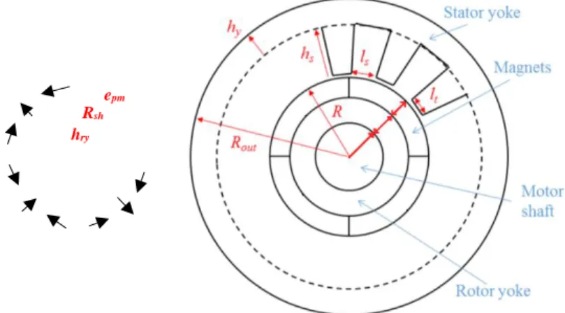
- The main sizes of radial flux non-salient electric motor (cf. Figure 1) - Approximate weight
- Approximate losses
- Approximate specific power of electric motor
Equations 8 to 12 express the calculation of main sizes implemented in TST. 𝑅 = √𝜆𝑃𝑒𝑚 4𝜋Ω𝜎𝑡 3 (8) 𝐿𝑚=2𝑅𝜆 (9) ℎ𝑦=𝑅𝐵𝑝𝐵𝑚 𝑦 (10) ℎ𝑠= 𝜋𝐴𝑟𝑚𝑠 𝑘𝑓𝑖𝑙𝑙𝑗𝑟𝑚𝑠(𝜋−2𝐵𝑚𝐵𝑡 ) (11) 𝑅𝑜𝑢𝑡= 𝑅 + ℎ𝑦+ ℎ𝑠 (12)
Where R is the inner stator radius, Rout is the outer stator radius, Lm is the active length, λ is the shape coefficient,
p is the pole pairs, By is the flux density in stator yoke with hy as height, Bt is the flux density in stator tooth with,
kfill is the fill factor.
Figure 1: Main sizes given by TST
4.2. Sizing electric motor: Surface Mounted –Permanent Magnet Synchronous Motor Tool
SM-PMSM (Surface Mounted Permanent Magnet Synchronous Motor) Tool is a sizing tool for electric machines based on TST assumptions [10-12]. Indeed, it allows giving more specifications of the electric motor design by choosing winding configuration and surface mounted Halbach permanent magnet rotor structure. SM-PMSM Tool takes as inputs: the TST outputs, permanent magnet polarization, flux density in rotor yoke and winding configuration. As outputs SM-PMSM tool gives additional sizes as shown in Figure 2, such as detailed weights and losses. Polarization orientation and thickness of Halbach permanent magnet epm are given according to [13].
Equations 13 to 16 express the calculation of additional sizes implemented in SM-PMSM tool. ℎ𝑟𝑦= 𝐵𝑦 𝐵𝑦𝑟ℎ𝑦 (13) 𝑅𝑠ℎ= 𝑅 − 𝑒𝑝𝑚− ℎ𝑟𝑦 (14) 𝑙𝑡=4𝐵𝐵𝑚𝑅 𝑡𝑁𝑠 (15) 𝑙𝑠=2𝜋𝑅𝑁 𝑠 − 𝑙𝑡 (16) where 𝐵𝑦𝑟 is the flux density in rotor and 𝑁𝑠 is the number of slots.
h
yFigure 2: Sizes given by SM-PMSM Tool 4.3. Lumped Parameter Thermal Model
The thermal model is created based on Lumped Parameter Thermal Modeling (LPTM) method.
It consists in creating a nodal network for a given system (the electric motor in this case) by discretizing it into finite volumes Vi. Each volume of this network is represented by a node and by some characteristics: mainly
thermal capacities, heat sources, densities and thermal conductivities. Connections between nodes are set to define heat transfer occurring between volumes of these nodes. Through these conductance components, heat paths are made. They determine heat fluxes inside the motor resulting from conduction, convection or radiation heat transfer modes. In our case, according to [14], radiation phenomenon has been neglected. Based on series of coupled equations including Newton’s law of cooling for convection heat transfer and Fourier’s law for conduction heat transfer in addition to the mass transport term of advection for fluid nodes, the system model can be elaborated. These equations and assumptions allow writing the thermal energy balance as a first order linear differential equation of temperature Ti to which the boundary conditions were integrated. It is represented as in Equation 17.
𝐶𝑖𝑑𝑇𝑑𝑡𝑖= ∑𝑗,𝑖≠𝑗𝐺𝑖𝑗(𝑇𝑗− 𝑇𝑖) + 𝑄𝑖̇ (17)
Where Ci [J/K] is the heat capacity, Gij [W/K] is the thermal conductance connecting nodes i to j which is the ratio
of heat flux Φij [W] (from i to j) to the temperature difference between (i and j) ∆Tij [K] inducing this heat: 𝐺𝑖𝑗= 𝛷𝑖𝑗/𝛥𝑇𝑖𝑗. 𝑄̇𝑖[W] is the total heat production in volume Vi. The thermal conductance expressions used in this model
according to the heat transfer mode are as follows: 𝐺𝑖𝑗𝑐𝑜𝑛𝑑,𝑎𝑥𝑖𝑎𝑙 =𝜆 𝑆𝑖𝑗
𝐿𝑖𝑗 for axial conduction 𝐺𝑖𝑗𝑐𝑜𝑛𝑑,radial= 2𝜋 𝜆 𝐻𝑧
𝑙𝑛 (𝑟𝑗/𝑟𝑖) for radial conduction 𝐺𝑆𝑐𝑜𝑛𝑣𝑖 = ℎ 𝑆𝑖 for convection
𝐺𝑖𝑗𝑓 = 𝑚̇ 𝑐
𝑝 for fluidic transport heat transfer
Where λ is the thermal conductivity of the medium [W/(mK)], Sij is the surface of heat transfer between volumes
represented by nodes i and j [m2], L
ij is the distance between nodes i and j [m], Hz is the height of the cylindrical
object [m], Si is the surface of exposition to convection [m2], 𝑚̇ is the fluid flow rate [kg/s], cp is the specific heat
[J/(kg K)].
LPTM is simulated on MATLAB software and can be adapted to the motor dimensions to allow predicting motor temperatures.
4.4. Sizing of Cooling System
The cooling system of the electric motor designed to achieve high specific power densities consists in liquid forced cooling. In the stator, it is similar to that of Totally Enclosed Water Cooled (TEWC) machines. Sizing a liquid cooling circuit relies mainly on hydraulic calculations based on thermal requirements. Such calculations allow the estimation of the pumping power needed for the liquid circulation in motor channels and heat exchanger. They are performed correspondingly to the heat dissipation in the motor, and are useful to determine the cooling system weight that should be added to the bare motor weight to find the value of the specific power density.
epm
hry
In order to carry out the design study of the complete cooling system of the machine, it would be convenient to begin with choosing the coolant and then setting its main thermal and physical parameters, and finally finding the heat transfer coefficients representing exchange of thermal energy between the fluid and the channel. These coefficients are determined based on Equations 18-21, that imply the calculation of dimensionless numbers (Nusselt, Prandtl and Reynolds numbers) for specified liquid channel geometry (mainly channel hydraulic diameter Dh) 𝑁𝑢𝐷ℎ= 𝑓 8(𝑅𝑒𝐷ℎ−1000)𝑃𝑟 1+12.7√𝑓8(𝑃𝑟2/3−1) (18) 𝑃𝑟 = 𝑐𝑝𝜇 𝜆𝑓𝑙𝑢𝑖𝑑 (19) 𝑅𝑒𝐷ℎ=𝜌𝑢𝐷𝜇ℎ (20) 𝑁𝑢𝐷ℎ= ℎ𝐷ℎ 𝜆𝑓𝑙𝑢𝑖𝑑 (21) Then, the hydraulic losses are determined using Equations 22-25 to find the pump head. Major losses:
𝐻𝑀 =
𝐾𝑝𝑖𝑝𝑒𝑉𝑝𝑖𝑝𝑒2
2𝑔 (22) Major losses coefficient:
𝐾𝑝𝑖𝑝𝑒= 𝑓𝑝𝑖𝑝𝑒𝐿𝑝𝑖𝑝𝑒 𝑑𝑝𝑖𝑝𝑒,𝑖𝑛𝑡 (23) Friction coefficient: 𝑓𝑝𝑖𝑝𝑒= 1 [ln( 𝑘 3.7𝑑𝑝𝑖𝑝𝑒,𝑖𝑛𝑡) +( 5.74 𝑅𝑒𝑝𝑖𝑝𝑒) 0.9 ] 2 (24)
Where dpipe,int is the internal diameter of the pipe, Lpipe is the total pipe length, g is the gravitational acceleration,
and k is the channel roughness coefficient. Minor losses:
𝐻𝑚= 𝐾𝐿𝑉𝑝𝑖𝑝𝑒2
2𝑔 (25)
Minor losses coefficient KL depends on the included hydraulic components, their geometries and the flow type.
Hydraulic components might be elbows, tees, valves, and others. Nomographs and tables in this case provide the coefficients of these components.
Finally, pump power is computed based on pump head and liquid flow rate considering the pump efficiency ηpump
as in Equations 26-29. Pump head: 𝐻𝑝𝑢𝑚𝑝= 𝐻𝑑𝑦𝑛𝑎𝑚𝑖𝑐+ 𝐻𝑠𝑡𝑎𝑡𝑖𝑐 (26) Dynamic head: 𝐻𝑑𝑦𝑛𝑎𝑚𝑖𝑐 = 𝐻𝑚+ 𝐻𝑀 (27) Static head: 𝐻𝑠𝑡𝑎𝑡𝑖𝑐= 0 (28) Pump power: 𝑃𝑝𝑢𝑚𝑝= 𝑞𝑔𝜌𝑓𝑙𝑢𝑖𝑑 𝜂𝑝𝑢𝑚𝑝 𝐻𝑝𝑢𝑚𝑝 (29)
With data obtained from this procedure, all components weights are determined based on their properties and to find pump weight some catalogs are needed.
4.5. Sizing approach
Sizing both the electric motor and its cooling system in order to reach high specific power is complex to carry out, given that several inputs are needed. For this purpose, a sizing approach using the electro-thermal models are proposed to overtake this existing complexity. To avoid exceeding the thermal limits of electric motors, a thermal constraint is introduced in the sizing procedure. This constraint is based on current density product which depends only on the effectiveness of cooling system.
Then an equivalent current density product 𝐴𝑗𝑒𝑞 is calculated to take into account all losses: < 𝐴𝑗𝑒𝑞>=
𝑃𝑖+𝑃𝑗+𝑃𝑤+𝑃𝑓
Where ktb is the end-winding coefficient. Ajeq should be lower than the permitted values (cf. Table 1) according to
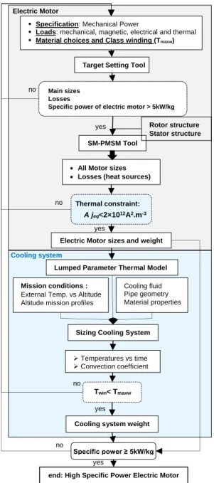
the chosen cooling method. Figure 3 shows the sizing procedure. It consists of six steps:
Step 1: assess the electric motor technologies required to reach high specific power using TST. Step 2: size surface mounted permanent magnet synchronous motor using SM-PMSM tool. Step 3: check thermal constraint according to cooling method chosen in step 1.
Step 4: assess the temperature inside electric motor. Step 5: size cooling system.
Step 6: assess the total weight.
5. SIZING OF HIGH SPECIFIC POWER ELECTRIC MOTOR WITH ITS COOLING SYSTEM 5.1. Specification and aeronautical propulsion environment
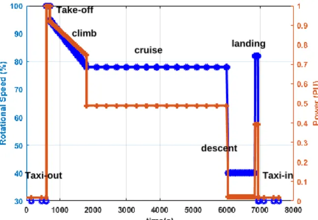
The mechanical power and rotational speed of one propeller of Hybrid Electric Aircraft is presented in Figure 4. Sizing point of electric motor is chosen in the Take-off phase, assuming that it should provide the highest power1. Electric motor and its cooling system are sized to reach specific power of 5kW/kg with efficiency higher than 96% in the Take-off flight phase.
Figure 3: Interaction between Electro-thermal models for sizing high specific electric motor with its cooling system
1 For confidentiality reason, exact power value will not be provided
Specification: Mechanical Power
Loads: mechanical, magnetic, electrical and thermal Material choices and Class winding (Tmaxw)
Target Setting Tool
Lumped Parameter Thermal Model
Sizing Cooling System Electric Motor sizes and weight
Mission conditions :
External Temp. vs Altitude Altitude mission profiles
Temperatures vs time Convection coefficient
Cooling system weight
no
yes
end: High Specific Power Electric Motor
Cooling fluid Pipe geometry Material properties
Thermal constraint:
A jeq<2×10¹²A2.m-3
All Motor sizes Losses (heat sources)
no yes Twin< Tmaxw Specific power ≥ 5kW/kg no yes Electric Motor Cooling system SM-PMSM Tool Rotor structure Stator structure Main sizes Losses
Specific power of electric motor > 5kW/kg
no
Figure 4. Mechanical power and rotational speed of propeller vs time
5.2. High specific power electric motor sizing
To reach a specific power of 5kW/kg some choices in the technological levels of materials and the cooling method are made in the electro-thermal models:
Using Vacoflux 48 with thickness of 0.35mm for stator and rotor yokes given that it has the highest flux density in electrical sheets and lower specific iron losses as shown in Figure 5;
Using SmCo permanent magnet given that it is less sensitive to the temperature than NdFeB permanent magnet as illustrated in Figure 6;
Halbach segmented permanent magnet to ensure sinewave airgap flux density as presented in Figure 7. In addition, axial segmentation of PM reduces eddy current losses;
Using insulation materials with 220°C thermal class;
Using twisted strands (cf. Figure 8) in order to reduce Joule losses resulting in less skin and proximity effects; Using external cooling technology for stator and inner cooling technology for shaft given that no partial
discharge are allowed in winding as shown in Figure 9.
The assessed loads, materials and geometrical choices using TST to achieve targeted specific power are summarized in Table 2. Table 3 summarizes the main sizes, estimated losses and weight of electric motor given by TST. Parameters of winding and rotor configurations chosen for SM-PMSM are given in Table 4. Sizes, weight and losses of surface mounted permanent magnet synchronous motor are grouped in Table 5. Losses and equivalent current density product profiles for operating at maximum torque are illustrated in Figure 10.
Figure 5: Comparison between electrical steels landing cruise climb Take-off Taxi-out Taxi-in descent
Figure 6: Comparison between NdFeB (N42UH) and SmCo (Recoma 33E)
Sizing using TST and SM-PMSM is validated using Finite Element Analysis as presented in Figure 11.
(a) (b)
Figure 7: (a) Halbach segmented permanent magnet, (b) Airgap flux density
Figure 8: Twisted strands
Figure 9: High specific power electric motor section airgap stator lamination rotor lamination shaft magnets end-winding
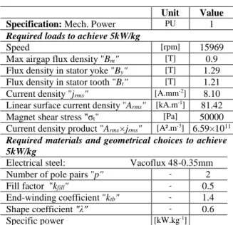
Unit Value Specification: Mech. Power PU 1 Required loads to achieve 5kW/kg
Speed [rpm] 15969
Max airgap flux density "Bm" [T] 0.9 Flux density in stator yoke "By" [T] 1.29 Flux density in stator tooth "Bt" [T] 1.21 Current density "jrms" [A.mm-2] 8.10 Linear surface current density "Arms" [kA.m-1] 81.42 Magnet shear stress "σt" [Pa] 50000 Current density product "Arms×jrms" [A².m-3] 6.59×10¹¹ Required materials and geometrical choices to achieve 5kW/kg
Electrical steel: Vacoflux 48-0.35mm Number of pole pairs "p" - 2 Fill factor "kfill" - 0.5 End-winding coefficient "ktb" - 1.4 Shape coefficient "λ" - 0.6
Specific power [kW.kg-1]
Table 2: Loads, materials and geometrical choices assessed using TST to achieve targeted specific power
Figure 10: Losses profiles vs time
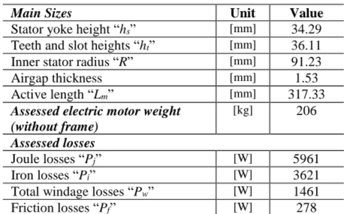
Main Sizes Unit Value
Stator yoke height “hs” [mm] 34.29 Teeth and slot heights “ht” [mm] 36.11
Inner stator radius “R” [mm] 91.23
Airgap thickness [mm] 1.53
Active length “Lm” [mm] 317.33
Assessed electric motor weight (without frame)
[kg] 206
Assessed losses
Joule losses “Pj” [W] 5961
Iron losses “Pi” [W] 3621
Total windage losses “Pw” [W] 1461
Friction losses “Pf” [W] 278
Table 3: Main sizes, weight and specific power of electric motor given by TST
Winding configuration
Number of phases "q" - 3 Number of slots "Ns" - 24 Rotor configuration
Polarization of PM (SmCo) [T] 1.16 Flux density in rotor yoke "Byr" [T] 1.4
Table 4: Winding and rotor configurations chosen in SM-PMSM Tool
Sizes Unit Value
Tooth width “lt” [mm] 10.58
Slot width “ls” [mm] 13.48
Airgap thickness [mm] 1.53
Permanent magnet thickness “epm” [mm] 9.00 Rotor yoke height “hry” [mm] 29.72
Shaft radius “Rsh” [mm] 50.98
Motor length [mm] 538.6
End winding coefficient (according to winding configuration) “ktb”
- 1.69
Weight of SM-PMSM (without frame) [kg] 236.5
Losses - -
Joule losses “Pj” [W] 7213
Iron losses “Pi” [W] 3621
Total windage losses “Pw” [W] 1837
Friction losses “Pf” [W] 670
Thermal constraint: <Ajeq> (without
armature reaction)
[A².m-3] 1.521×10¹²
Specific power of SM-PMSM [kW.kg-1] 6.03
Table 5: Sizes, weight and losses given by SM-PMSM Tool
5.3. Cooling system design
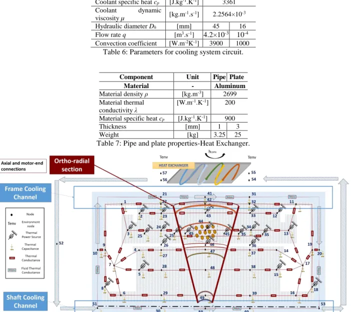
Considering the motor design parameters obtained, and its losses profiles, a thermal nodal network have been defined to represent the motor and the cooling system (Figure 12). In the motor structure and along the shaft axis, there are three identical radial sections to assess the evolution of motor and liquid temperatures in different machine zones, according to the fluid flow direction. Shaft and frame are assigned some axial and radial nodes connected to cooling medium, in turn represented by fluid nodes. The radial section and connections in the motor structure are detailed in [15]. The cooling system is based on a liquid water-glycol circuit. The water-glycol coolant extracts the heat flux produced in the motor by circulating in an annular channel around the stator and in an axial channel
at the center of rotor shaft. Then the liquid is conducted into the heat exchanger allowing the evacuation of the heat into the outside air around the plane. Figure 12 shows nodes’ locations 1 to 57 with axial and motor-end connections. In a practical approach, the heat exchanger in this case is a pipe embedded at the surface of a cold plate corresponding to the nacelle containing the motor. This nacelle has a total surface of 2.3 m² and the pipe diameter equals 4.5 cm with 1 mm of thickness. In the thermal model, a set of parameters and hypotheses are used for channels’ characterization. The adopted parameters of the stator and shaft channels in the motor are given in Table 6.
The total flow rate of the coolant circulation and the coolant properties are used in order to determine the hydraulic losses and the pump power according to Equations 22-29.
Some additional properties are needed for calculations including physical and geometrical characteristics of the pipe and plate. These properties include components thicknesses and material choices. They depend on the flow rate, coolant pressure, application and the provider’s options. A group of these parameters is found in Table 7 for applied calculations, where the value of the pipe and channels roughness is: k=3.10-4.
Zone Unit Stator Shaft
Coolant - Water-Glycol
Coolant density ρ [kg.m-3] 1065 Coolant thermal
conductivity λfluid [W.m
-1K-1] 0.3937 Coolant specific heat cp [J.kg-1.K-1] 3361 Coolant dynamic viscosity µ [kg.m -1.s-1] 2.2564×10⁻³ Hydraulic diameter Dh [mm] 45 16 Flow rate q [m3.s-1] 4.2×10⁻³ 10-4 Convection coefficient [W.m-2K-1] 3900 1000
Table 6: Parameters for cooling system circuit.
Component Unit Pipe Plate Material - Aluminum
Material density ρ [kg.m-3] 2699 Material thermal
conductivity λ
[W.m-1.K-1] 200
Material specific heat cp [J.kg-1.K-1] 900
Thickness [mm] 1 3
Weight [kg] 3.25 25
Table 7: Pipe and plate properties-Heat Exchanger.
Figure 12: Axial and ortho-radial sections of half SM-PMSM electric motor including its cooling system with LPTM nodes locations, and axial and motor-end connections.
The total weight can now be determined as the sum of the weights of motor, pipe, heat exchanger, coolant and pumping system, considering a pump efficiency of around 60% (η=0.6).
In Parker Pump and Motor Division [16] an adequate pump is chosen for this application weighing no more than 14 kg. An example of adequate pump properties are given in Table 8.
Pump
Normal Operating Pressure [bars] 206
Maximum Speed [rpm] 3646
Length [cm] 26.16
Height [cm] 21.84
Width [cm] 17.27
Weight [kg] 14
Table 8: Pump properties from [16].
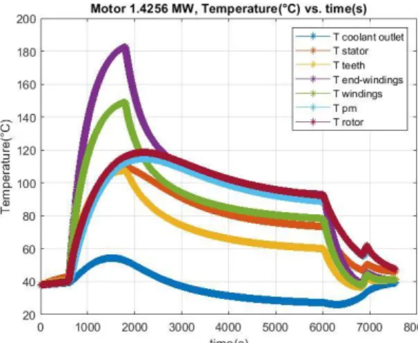
Coolant weight depends on the coolant choice. For water-glycol, the estimated liquid in channels and heat exchanger weighs around 31 kg. Resulting temperatures evolution in motor are depicted in Figure 13 according to the mission profile given in Figure 4. It shows the positions of the nodes and the conductance connections. In this figure, T coolant outlet is the outlet cooling temperature of the coolant (node 53), T stator corresponds to node 12. T teeth is the temperature at node 35. Stator windings hottest point (T windings) is at the middle section and is given at node 34.
Figure 13: Temperature evolution during flight mission in the designed high specific power electric motor.
The rear-end nodes of the motor have higher temperatures than front motor side, so the highest temperature of end-windings is given at node 13 (T end-windings in the figure). Finally, rotor temperatures, T pm of permanent magnet and T rotor of iron structure, are given at nodes 14 and 15.
Temperatures at the end-winding hot-spot zone remain below the thermal limits with the adopted cooling techniques for the chosen winding impregnation thermal class.
6. TECHNOLOGICAL SOLUTIONS TO EXCEED TARGETED SPECIFIC POWER
Several technological solutions have been proposed. They allow to double achieved specific power. Some of them are under research and some of them are marketed such as:
High energy and high temperature Grain Boundary Diffusion (GBD) Neodymium Iron Boron permanent magnet "GBD NdFeB".
Inorganic insulation materials (class 240°C). Using inorganic insulation materials allow increasing current density and frequency levels.
Carbon fiber sleeves with high permissible stresses allow peripheral speeds higher than 150m/s. Very thin electrical sheets to reduce Iron losses. Their thickness down to 50µm.
Litz wires to reduce winding losses at very high frequency.
Bring the liquid coolant closer to the winding using small pipe embedded at the periphery of the windings.
7. CONCLUSION
The electro-thermal models developed in this paper are devoted for sizing high specific power electric motor with its cooling system. Target Setting Tool is used to assess the technologies and to make quick trade off on specific
power. SM-PMSM Tool is used to calculate accurately the sizes and the losses of the electric motor.
LPTM nodal network for electric motor and its associated cooling system is used to predict motor temperatures. In this model the cooling system design is integrated. Details on sizing of the cooling system hydraulic circuit are presented. Calculations are applied on the conceived high specific power electric motor in the frame of a hybrid-electric propulsion.
ACKNOWLEDGEMENT
This project has received funding from the Clean Sky 2 Joint Undertaking under the European Union’s Horizon 2020 research and innovation program under grant agreement No 715483.
REFERENCES
[1] Power trip: HASTECS energizes the path to hybrid-powered flight, Available website https://www.cleansky.eu/power-trip-hastecs-energizes-the-path-to-hybrid-powered-flight-0
[2] J. Pyrhönen, T. Jokinen, V. Hrbovcovà, 'Design of rotating electrical machines', Edition John Wiley 2008. [3] S. Nategh, A. Krings, O. Wallmark, and M. Leksell, “Evaluation of Impregnation Materials for Thermal
Management of Liquid-Cooled Electric Machines,” IEEE Transactions on Industrial Electronics, vol. 61, no. 11, pp. 5956–5965, Nov. 2014.
[4] B. Assaad, K. E. kadri Benkara, S. Vivier, G. Friedrich, and A. Michon, “Thermal Design Optimization of Electric Machines Using a Global Sensitivity Analysis,” IEEE Transactions on Industry Applications, vol. 53, no. 6, pp. 5365–5372, Nov. 2017.
[5] J. Pyrhönen, P. Lindh, M. Polikarpova, E. Kurvinen, and V. Naumanen, “Heat-transfer improvements in an axial-flux permanent-magnet synchronous machine,” Applied Thermal Engineering, vol. 76, pp. 245–251, Feb. 2015.
[6] M. Galea, C. Gerada, T. Raminosoa, and P. Wheeler, “A Thermal Improvement Technique for the Phase Windings of Electrical Machines,” IEEE Transactions on Industry Applications, vol. 48, no. 1, pp. 79–87, Jan. 2012.
[7] V. Madonna, A. Walker, P. Giangrande, G. Serra, C. Gerada, and M. Galea, “Improved Thermal Management and Analysis for Stator End-Windings of Electrical Machines,” IEEE Transactions on Industrial Electronics, vol. 66, no. 7, pp. 5057–5069, Jul. 2019.
[8] N. Putra and B. Ariantara, “Electric motor thermal management system using L-shaped flat heat pipes,” Applied Thermal Engineering, vol. 126, pp. 1156–1163, Nov. 2017.
[9] C. Tighe, C. Gerada, and S. Pickering, “Assessment of cooling methods for increased power density in electrical machines,” in 2016 XXII International Conference on Electrical Machines (ICEM), 2016, pp. 2626– 2632.
[10] Y. Lefevre, S. El-Aabid, J.F. Llibre, C. Henaux, S. Touhami, 'Performance assessment tool based on loadability concepts', International Journal of Applied Electromagnetics and Mechanics, vol. 59, no. 2, pp. 687-694, 2019.
[11] S. Touhami, Y. Lefevre, J.F. Llibre, 'Joint design of Halbach Segmented Array and Distributed Stator Winding', IEEE International Conference on Electrical Machines (ICEM), 3-6 Sept. 2018, Greece.
[12] P. Collin, S. Touhami, D. Malec, Y. Lefevre, J.F. Llibre, ' Design of Electric Machine Taking into Account the Partial Discharges Phenomena for Future Hybrid Propelled Aircrafts', International Conference on More Electric Aircraft 2019 (MEA 2019), 6 February 2019 - 7 February 2019 (Toulouse, France).
[13] S. Touhami, Y. Lefevre, J.F. Llibre, 'Original Optimization Procedures of Halbach Permanent Magnet Segmented Array', 19th International symposium on Electromagnetic Fields in Mechatronics, Electrical and
Electronic Engineering, 29-31st August 2019, France.
[14] A. Boglietti, A. Cavagnino, M. Parvis, and A. Vallan, “Evaluation of radiation thermal resistances in industrial motors,” IEEE Transactions on Industry Applications, vol. 42, no. 3, pp. 688–693, May 2006. [15] A. Zeaiter and M. Fénot, “Thermal Sensitivity Analysis of a High Power Density Electric Motor for
Aeronautical Application,” in 2018 IEEE International Conference on Electrical Systems for Aircraft, Railway, Ship Propulsion and Road Vehicles International Transportation Electrification Conference (ESARS-ITEC), 7-9 Nov. 2018, UK.
![Table 1: permitted values of electromagnetic loads for non-salient synchronous machine according to cooling technology[2]](https://thumb-eu.123doks.com/thumbv2/123doknet/14380376.505905/3.892.283.611.125.308/permitted-electromagnetic-salient-synchronous-machine-according-cooling-technology.webp)