Publisher’s version / Version de l'éditeur:
Vous avez des questions? Nous pouvons vous aider. Pour communiquer directement avec un auteur, consultez la
première page de la revue dans laquelle son article a été publié afin de trouver ses coordonnées. Si vous n’arrivez pas à les repérer, communiquez avec nous à PublicationsArchive-ArchivesPublications@nrc-cnrc.gc.ca.
Questions? Contact the NRC Publications Archive team at
PublicationsArchive-ArchivesPublications@nrc-cnrc.gc.ca. If you wish to email the authors directly, please see the first page of the publication for their contact information.
https://publications-cnrc.canada.ca/fra/droits
L’accès à ce site Web et l’utilisation de son contenu sont assujettis aux conditions présentées dans le site LISEZ CES CONDITIONS ATTENTIVEMENT AVANT D’UTILISER CE SITE WEB.
Architectural Engineering Institute Conference (AEI 2008) [Proceedings], pp. 1-11, 2008-09-25
READ THESE TERMS AND CONDITIONS CAREFULLY BEFORE USING THIS WEBSITE. https://nrc-publications.canada.ca/eng/copyright
NRC Publications Archive Record / Notice des Archives des publications du CNRC :
https://nrc-publications.canada.ca/eng/view/object/?id=3730a091-e67a-49d7-a6de-73cf3b60d56d https://publications-cnrc.canada.ca/fra/voir/objet/?id=3730a091-e67a-49d7-a6de-73cf3b60d56d
NRC Publications Archive
Archives des publications du CNRC
This publication could be one of several versions: author’s original, accepted manuscript or the publisher’s version. / La version de cette publication peut être l’une des suivantes : la version prépublication de l’auteur, la version acceptée du manuscrit ou la version de l’éditeur.
Access and use of this website and the material on it are subject to the Terms and Conditions set forth at
Impact of fastener-deck attachment on the wind uplift resistance of mechanically attached roofs
http://irc.nrc-cnrc.gc.ca
I m p a c t o f f a s t e n e r - d e c k a t t a c h m e n t o n t h e
w i n d u p l i f t r e s i s t a n c e o f m e c h a n i c a l l y
a t t a c h e d r o o f s
R e p o r t N R C C - 5 0 3 0 9
Molleti, S.; Ko, S.K.P.; Baskaran, B.A.
A version of this document is published in / Une version de ce document se trouve dans:
Architectural Engineering Institute Conference (AEI 2008), September 25, 2008
The material in this document is covered by the provisions of the Copyright Act, by Canadian laws, policies, regulations and international agreements. Such provisions serve to identify the information source and, in specific instances, to prohibit reproduction of materials without written permission. For more information visit http://laws.justice.gc.ca/en/showtdm/cs/C-42
Les renseignements dans ce document sont protégés par la Loi sur le droit d'auteur, par les lois, les politiques et les règlements du Canada et des accords internationaux. Ces dispositions permettent d'identifier la source de l'information et, dans certains cas, d'interdire la copie de documents sans permission écrite. Pour obtenir de plus amples renseignements : http://lois.justice.gc.ca/fr/showtdm/cs/C-42
IMPACT OF FASTENER-DECK ATTACHMENT ON THE WIND
UPLIFT RESISTANCE OF MECHANICALLY ATTACHED
ROOFING SYSTEMS
Suda Molleti, Ph.D1, Steven Kee Ping Ko, M.Eng.2 Bas A. Baskaran Ph.D., P.Eng.3C
1
Research Officer, 2 Technical Officer, 3CSenior Research Officer
National Research Council, 1200 Montreal Road, Ottawa, ON, Canada, K1A OR6; Ph (613) 990-3616;Fax (613) 998-6802; Email: bas.baskaran@nrc.ca
Abstract
A roofing system (RS) consists of a waterproof membrane, mechanical attachments, cover board (if present), insulation, and vapor or air barrier (retarder – if present). A roof assembly (RA) is defined as an RS that includes a structural deck. Wind uplift ratings are obtained by subjecting RA mockups to dynamic wind loading. Mechanically Attached Roofing Systems (MARS) are one particular type of roof assemblies in which the membrane is attached to the structural deck using mechanical fasteners. The strength of the fastener-deck interface is an important aspect in the successful design of the wind uplift resistance of mechanically attached roof systems. To quantify the fastener-deck interface influence on the wind uplift performance of MARS, seven different roofing assemblies were constructed and tested under dynamic conditions. The experimental investigation identified three parameters namely deck grade, deck gauge and fastener type that have influence on the wind uplift resistance of MARS. Based on this component characterization, fastener pullout resistance (FPR) is identified as a verification factor for system wind resistance estimation.
Key words: Steel decks, tensile strength, fasteners, pullout resistance, wind uplift,
dynamic testing.
1. Introduction
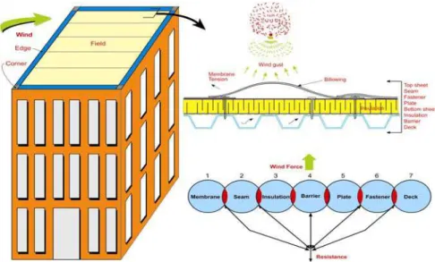
In conventional roof assemblies, the waterproof membrane is located at the top of the insulation and is directly exposed to environmental elements. The conventional roof systems may be either the Single-ply roof (SPR) or a Built up roof (BUR). Mechanically Attached Roofing System (MARS) represents one type of single-ply roofing system. In North America over 50% of low slope applications are made with MARS. Market survey indicates that there is a continuous growth for MARS. Nevertheless, MARS continues to face the greatest challenge of resisting the variable wind uplift forces that act upon them. Figure 1 illustrates the wind dynamics on MARS along the Resistance Link Diagram, a concept developed to evaluate its wind uplift resistance. As shown in Figure 1, in MARS, the insulation is located above the
deck. The waterproof membrane such as a thermoset, thermoplastic or modified bitumen is placed on top of the insulation and is attached to the structural deck using mechanical fasteners. The membrane attachment locations are then overlapped with the adjacent membrane to form seams. Wind-induced suction lifts the membrane between the attachments and causes membrane elongation and billowing. As shown in Figure 1, Force Resistance Link Diagram, all resistance links should remain connected for the system to be durable and in place. Failure occurs when the wind uplift force is greater than the resistance of any one or more of these links.
Mechanically Attached Roofing Assembly is defined as MARS that includes a structural deck. Henceforth, for easy reference the mechanically attached roofing assembly will be addressed as MARS throughout the paper. As seen from the force resistance diagram in Figure 1, the fastener-deck interface represents one of the resistance links to wind uplift forces. Its strength is characterized by a parameter known as Fastener Pullout Resistance (FPR).
Figure 1: Wind Effects on Mechanically Attached Roofing System (MARS) In MARS, the structural deck could be concrete or steel, however, the steel decks have been used for years and is the primary decking material. ASTM A1008 and ASTM A653 classifies steel deck for roofing applications, and the most common grades of decking in the roofing industry are Grade 33 20, Grade 33 22, Grade 80 -20 and Grade 80 -22 (Baskaran and Smith, -2005). The numbers, 33 (227 Mpa) and 80 (550 Mpa) represent the yield strength of the steel deck in kilopounds per square inch (kis) while the number, 20 (0.91 mm) and 22 (0.76) represent the gauge/thickness of the steel deck. It is this difference in deck grades or minimum yield strength that is causing a lot of concerns and confusion with the roofing industry from the wind uplift perspective. Similarly, the roofing industry has many choices regarding the roofing fasteners available. Designing with the appropriate fastener-deck interface is essential for achieving the required wind uplift resistance of MARS.
To address the strength issue of fastener-deck interface, Baskaran et. al (2007) conducted fastener pullout experimental testing using three common roofing fasteners; namely; #14 [4 mm (0.17 in) dia.], #15 [7 mm (0.281 in.) dia.] and #21 [8.5 mm (0.331 in.) dia.], and the above mentioned four different steel decks. The results indicated that FPR increases with increase in the gauge and yield strength of steel deck, and fastener thread diameter.
Analyzing it from the component level, the present research extends to the assembly level by constructing seven different roofing assemblies with different fastener-deck combinations, and by testing under dynamic conditions. This experimental program has been initiated at NRC’s IRC. The roof assembly responses are measured by two design indicators: pressure and force. By presenting a comparison between these seven roofing assemblies, the paper quantifies the role of fastener-deck interface on the strength of low slope roof assemblies.
2. Experimental Approach
Dynamic Roofing Facility and Wind Test Protocol
Experimental work was carried out at the Dynamic Roofing Facility (DRF), established at NRC’s IRC. Baskaran and Lei (1997) provide a detailed documentation of the facility’s features. As shown in Figure 2 (a), the DRF consists of a bottom frame of adjustable height upon which roof specimens are installed and a movable top chamber. The bottom frame and top chamber are 6100 mm (240 in.) long, 2200 mm (86 in.) wide and 800 mm (32 in.) in height. The top chamber is equipped with six windows for viewing, and with a gust simulator, which consist of a flap valve connected to a stepping motor through a timing belt arrangement. Wind suctions as high as 10 kPa (209 psf) over the roof assembly is produced by a 50 HP (37 kw) fan having a flow rate of 2500 L/sec (5300 cfm).
All the constructed test specimens were subjected to the CSA A123.21-04 dynamic load cycle as shown in Figure 2 (b). Details of the method by which the load cycle was developed can be found in Baskaran et al (1999). As shown in the figure, it has five rating levels (A to E). To evaluate a roof assembly for a specific wind resistance, testing starts at Level A and continues by moving from one level to the next. To obtain a rating, all specified numbers of gusts in each level must be completed without any resistance link failure. As discussed in the Figure 1, the system is considered to have “Failed”, if any one-resistance link fails.
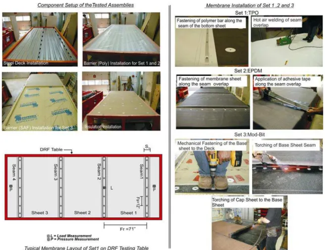
Test Assemblies Setup
Using the above test facility (Figure 3) the present study evaluated seven assemblies with different fastener-deck combinations. These seven assemblies can be categorized into three sets based on the roof membrane type as:
Set 1: Thermoplastic Assemblies
TP22-80-15: Steel Deck = 22 Ga - 80 ksi, Fastener = #15, FPR = 3kN (685 lbf)
TP20-80-15: Steel Deck = 20 Ga - 80 ksi, Fastener = #15, FPR = 3.9kN (893 lbf)
.
Figure 2: Test Approach for Wind Uplift Testing of Roofing Assemblies
Set 2: Thermoset Assemblies
TS22-33-14: Steel Deck = 22 Ga - 33 ksi, Fastener = #14, FPR = 1.8 kN (420 lbf)
TS22-80-14: Steel Deck = 22 Ga - 80 ksi, Fastener = #14, FPR = 2.9 kN (660 lbf)
Set 3: Modified-Bituminous Assemblies
MB22-33-14: Steel Deck = 22 Ga - 33 ksi, Fastener = #14, FPR = 1.7 kN (382 lbf)
MB20-80-14: Steel Deck = 20 Ga - 80 ksi, Fastener = #14, FPR = 2.7 kN (651 lbf) To evaluate the strength of the fastener-deck interface, the present study evaluated three different fastener types: #14, #15 and #21 with the combination of 22 Ga –33 ksi, 22 Ga – 80 ksi, 20 Ga – 80 ksi steel decks. The main difference in theses fastener types, as shown in Figure 3, exists in the fastener head, tip, thread, and shank diameter. To reference each tested assembly type, the three parameters namely the deck gauge, yield strength and fastener type have been used.
Apart from the variation in membrane type and fastener-deck interface, the other components of the roof assembly, namely, air/vapour barrier and insulation were similar for all the seven assemblies. As the roof installation is similar for all the tested assemblies the construction procedure can be classified into five steps:
1.Deck Installation: One full sheet of 914 mm (36 in.) wide and two cut pieces of 610 mm (24 in.) and 483 mm (19 in.) wide steel sheets were installed along the table length as shown in Figure 4. All the tested steel decks as mentioned above had a profile height of 38 mm (1.5 in.) and a flute width of 150 mm (5.9 in.). The black dotted lines as shown in Figure 4 indicate the deck overlaps. The decks were fastened to the steel joists at every flute.
2. Barrier/retarder Installation: For Set 1 and 2, a 150μm (6-mil) polyethylene film was used as a vapour barrier. To support the polyethylene film, a 12 mm (½ in.) gypsum board is laid above the steel deck and upon which polyethylene film was loose laid as shown in Figure 4. In Set 3, a self-adhered film (SAF) was used as a vapour barrier. The SAF is a 75μm (3 mil) thick sheet, which is adhered to the steel deck. It is composed of SBS modified bitumen and is surface-reinforced with trilaminate woven polyethylene. Figure 4 also illustrates the installation setup of SAF.
3.Insulation Installation: As shown in Figure 4, 51 mm (2 in.) thick polyisocyanurate insulation boards with a compressive strength of 170 kPa (25 psi) were used. The layout comprised of a single layer of insulation of four full boards of 1219 mm x 2006 mm (48 in. x 79 in.) and one partial board of 1118 mm x 2006 mm (44 in. x 79 in.) installed with the long edges perpendicular to the steel deck flutes. The insulation boards were mechanically fastened to the steel deck with eight fasteners per board.
4.Waterproof Membrane Installation: Figure 5 shows the typical installation procedure of the roofing membrane for the three sets. In Set 1, thermoplastic assemblies, a reinforced Thermoplastic Olefin (TPO) membrane sheet was used as the waterproof membrane. The membrane has a thickness of 1125 μm (45 mil) and a width of 1981 mm (78 in.). Geometric details of a typical tested assembly are also described in Figure 4. As shown in Figure 4, the layout comprised of three full-width sheets and a dummy sheet at each end. The four seams shown in Figure 4 indicate the fasteners’ locations. The membrane attachment was done by fastening the sheets at fastener row spacing (Fr) of 1790 mm (71 in) and a fastener spacing (Fs) of 305 mm (12 in.) along the seam. For these assemblies, # 15 and #21 fasteners were used with 57- mil (0.057 in.) thick polymer batten bar having a width of 25 mm (1 in).
For Set 2, thermoset assemblies, Ethylene Propylene Diene Monomer(EPDM) membrane was used. Being a rubber polymer, EPDM cannot be hot air welded, therefore, its application follows the method of “In-seam attachment”. As shown in Figure 4, the membrane seam is mechanically fastened to the deck using 50 mm (2 in.) diameter plastic plates and 83 mm (3 ¼ in.) long #14 fasteners, and the overlap seams were primed with adhesive and sealed by using seam tape to make a symmetrical joint. The overall membrane assembly configuration consisted of three seams with two full sheet widths having a fastener row spacing (Fr) of 1980 mm (78 in.) and fastener spacing (Fs) of 300 mm (12 in).
In Set 3, mechanically attached modified bituminous roof assemblies, the waterproof membrane typically consists of a minimum of two layers: the base sheet and the cap sheet. Both the base and cap sheets come in width of 990 mm (39 in.). The base sheet is installed as the first layer over the insulation. It is affixed to the steel deck along the seam using 83 mm (3 ¼ in.) long # 14 fasteners and 50 mm (2 in). diameter metal plates with Fs of 150 mm (6 in.). The seam’s overlaps of the base sheet are then torched as shown in Figure 5. With the base sheet installed, the cap sheet is installed by torching it onto the base sheet. The overall membrane layout comprised 5 full sheets with six seams having fastener row spacing (Fr) of 900 mm (35.6 in.)
In figure 4, P, and L respectively represent the pressure and force measurement locations.
3. Results and Discussion
The strength of the fastener-deck interface is characterized by the physical and mechanical properties of the deck and fasteners. Through this experimental testing, the present study identified three parameters that characterize the strength of the
fastener-deck interface and have an influence on the wind uplift resistance of MARS. The results are quantified based on these three investigative parameters and are discussed below:
Effect of Deck Gauge
Thermoplastic assemblies TP22-80-15 and TP20-80-15 represent the two assemblies which had variation in the deck gauge. TP22-80-15 used gauge 22 steel deck, while TP20-80-15 used gauge 20. Figure 5 shows the typical pressure measured and load time histories of TP22-80-15. The measured wind uplift resistance data indicates that TP22-80-15 passed
the first four levels (90, 113,135 and 157 psf) of the CSA load cycle. Since it failed at Level E sequence 4, it obtained a wind uplift rating of 7.5 kPa (157 psf). In the case of TP20-80-15, the wind uplift rating is 8.6 kPa (180 psf), as it successfully sustained all five levels (90, 113, 135,157 psf and 180 psf) without any failure of the assembly. The test had to be stopped as it reached the maximum pressure level of the CSA dynamic cycle. The measured fastener loads of TP22-80-15 and TP20-80-15 at their sustained pressures were 2.8 kN (640 lbf) and 3.1 kN (706 lbf) respectively.
With all similar components, except the steel deck gauge, TP20-80-15 showed a 13% increase in wind uplift resistance compared to TP22-80-15 , and this can be explained or related to the strength of the fastener-deck interface. TP22-80-15 and TP20-80-15 with # 15 fastener have a FPR of 3 kN (685 lbf) and 3.9 kN (893 lbf) respectively. The FPR comparison indicates 23% increase with the increase in the gauge of the deck. During wind uplift testing, this higher fastener-deck attachment strength of TP20-80-15 offered higher pullout resistance to the membrane-induced load, which allowed the assembly to sustain higher wind uplift pressures compared to TP22-80-15. Observing the failure modes as shown in Figure 5 can also draw similar inference. In TP22-80-15, the membrane load exceeded the resistance offered by 22 Ga deck, which allowed the fasteners to pull out from the deck. Whereas in TP20-80-15, the capability of 20 Ga deck to resist high pullout loads allowed it to sustain higher uplift pressures without any sign of failure.
Effect of Fastener Type
Using all the components in TP22-80-15 , including the gauge and yield strength of deck, the # 15 fastener in TP22-80-15 was replaced by #21 for the assembly TP22-80-21. The measured pressure and load time history of TP22-80-21 indicated that it sustained a maximum wind uplift pressure of 8.4 kPa (175 psf) with a corresponding fastener load of 2.9 kN (672 lbf).
Fastener # 21 has a shank diameter of 8.4 mm (0.331 in.), which was almost 15% greater than the shank diameter of the # 15 fastener [7 mm (0.281 in.)] used in TP22-80-15. The #21 fastener when connected to 22 Ga –80-ksi deck yielded a FPR of 5050 N (1148 lbf), which was 23% greater than the FPR of TP22-80-15. Due to the larger diameter of the #21 fastener, it provided greater contact strength with the deck, which translated into higher FPR and higher wind uplift resistance. The failure mode, as shown in Figure 5, indicates membrane tear along the plastic batten bar in the seam. In this case, the fastener-deck combination was the strongest link, while the membrane was the weakest link.
Figure 5: Results Obtained from the Wind Uplift Investigation
Evaluating the wind uplift performance of the above three assemblies (TP22-80-15: 7.5 kPa; TP20-80-15: 8.6 kPa; TP22-80-15: 8.4 kPa) also provides the opportunity for assembly optimization. More discussion about assembly optimization can be found in Baskaran et al (2006). In order to improve the performance of TP22-80-15, two options exist, one is to increase the thickness of the deck to 20 Ga as in TP20-80-15, and the other is to use a larger diameter fastener (# 21) as in TP22-80-21. As discussed above, both options could contribute to improving the wind uplift performance of TP22-80-15. However, considering a scenario of re-roofing, option 1 may cost the building owner more in comparison to option 2. This is due to the fact that replacing a deck tends to be more expensive in terms of both material and labour as compared to replacing fasteners.
Effect of Deck Grade
TS22-33-14, and TS22-80-14 of the thermoset assemblies represent the two assemblies, which had variation in the deck grades (33 vs.80). When subjected to dynamic wind load cycles, TS22-33-14, sustained a wind uplift pressure of 4.3 kPa (90 psf) with a fastener load 1.5 kN(345 lbf), while TS22-80-14 sustained a wind uplift rating of 5 kPa (105 psf) with corresponding fastener load of 1.3 kN (293 lbf). Correlating the wind uplift resistance with the strength of the fastener-deck interface indicates that TS22-80-14 with FPR of 2.9 kN (660 lbf) sustained a TS22-80-14% higher wind uplift resistance when compared to TS22-33-14, which had FPR of 1.8 kN (420 lbf). This increase in FPR could be attributed to the higher yield strength of the 80-ksi deck., which during the
wind uplift testing also offered high resistance to the membrane induced fastener load.
The wind uplift failure modes of these assemblies as shown in Figure 5, indicate that
TS22-33-14, which had 33-ksi deck failed due to fastener pullout from the deck, whereas in TS22-80-14, the membrane became the weakest link and failed due to membrane tear around the fastener plate. It can be concluded that the greater the yield strength of the deck the higher will be its fastener pullout resistance, and ultimately, it would have higher wind uplift resistance.
Combined Effect of Deck Grade and Thickness
Mod-bit assemblies, MB22-33-14 and MB20-80-14, represent the combination for variation in both deck grade and deck thickness (22 vs. 20 and 33 vs.80). With the similar fastener type, but variation in the deck properties, MB22-33-14 sustained an uplift pressure of 4.3 kPa (90 psf) with fastener load of 0.6 kN (137 lbf), and MB20-80-14 without any failure sustained an uplift pressure of 5.7 kPa (120 psf) with fastener load of 0.7 kN (178 lbf). Examination of the failure mode of MB22-33-14 as shown Figure 5, indicated that the seam of the base sheet delaminated, which caused the premature failure of the roof assembly. In addition to this primary failure mode, it also had symptoms of secondary failure mode of fastener plates loosening with fasteners slightly pulled. Similar exercise of FPR correlation with the wind uplift performance indicates that MB20-80-14, which had higher FPR of 2.9 kN (651 lbf) sustained 25% higher wind uplift rating compared to MB22-33-14, which had a lower FPR of 1.7 kN (382 lbf). This increase in the wind uplift resistance is the result of the high pullout strength of 20 Ga-80 ksi deck, which is a combination of higher gauge and higher yield strength. Even though the fastener had a smaller shank diameter, when connected to the 20 Ga-80 ksi deck, it provided a strong connection strength, which enabled MB20-80-14 to withstand high wind uplift pressures.
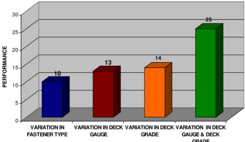
Figure 6 presents the results summarizing the research findings from the present investigative study. The plotted data has been generalized with respect to the three assembly sets. As shown in the figure, the data indicates that by increasing the fastener diameter, deck grade or deck gauge an increase of 10 to 15% in the wind uplift performance can be expected. Whereas, if a steel deck having higher gauge and grade is used an increase of 25% and beyond can be expected in the wind uplift performance of that roof assembly. As the present study did not investigate all the possible combinations of fastener-deck interfaces within each assembly set, this generalized data only provides the estimation of how much each parameter could influence the wind uplift performance of the roof assembly. However, data variation in the improvement of the wind uplift performance can be expected based on the assembly set being tested.
4. Conclusion
Fastener-deck interface strength constitutes an important parameter in the successful design of mechanically attached roof assemblies. To investigate its effect on the wind uplift resistance of MARS, seven mockups of mechanically attached assemblies with three different membrane types and having different fastener-deck combinations were tested using the dynamic wind load cycle. From the obtained results, three parameters
10 13 14 25 0 5 10 15 20 25 30
% INCREASE IN WIND UPLI
F PERFO RMANCE VARIATION IN FASTENER TYPE VARIATION IN DECK GAUGE VARIATION IN DECK GRADE VARIATION IN DECK GAUGE & DECK
GRADE
Figure 6: Effect of Fastener-Deck Interface Properties on the Wind Uplift Performance of MARS
characterizing the fastener deck interface strength namely, deck gauge, deck grade and fastener type were identified as the influencing parameters. Based on the presented results and discussions, the following conclusions can be drawn:
- Assemblies tested on higher gauge (20Ga) or higher yield strength decks (80 ksi) sustained higher wind uplift pressures compared to assemblies of lower gauge and lower yield strength decks.
- Assemblies tested with different fastener types showed that the larger shank diameter fasteners provided greater connecting strength, thus enabling the assembly to sustain higher wind uplift pressures.
- Within each assembly set, the FPR comparison indicated that the assembly with higher FPR sustained higher wind uplift ratings compared to the assembly with lower FPR. Therefore FPR could be used as a verification factor for system wind resistance estimation.
References
ASTM A1008/A1008M-07a Standard Specification for Steel, Sheet, Cold-Rolled, Carbon, Structural, High-Strength Low-Alloy, High-Strength Low-Alloy with Improved Formability, Solution Hardened, and Bake Hardenable
American Society for Testing and Materials, A653/A 652M-03 , “Standard specifications for steel sheet, zinc coated (galvanized) or zinc-iron-alloy-coated (galvannealed) by the hot-dip process”.
Baskaran, A. and Lei, W. (1997), "A New Facility for Dynamic Wind Performance Evaluation of Roofing Systems", Proceedings of the Fourth International Symposium
on Roofing Technology, NRCA/NIST, Washington, D.C., U.S.A., pp. 168 -179.
Baskaran, A.; Chen, Y.; and Vilaipornsawai, U. (1999) "A New Dynamic Wind Load Cycle to Evaluate Flexible Membrane Roofs" ,Journal of Testing and Evaluation, ASTM, vol.27, No 4, pp.249 -265.
Baskaran, A., Smith, T.L., (2005), “A Guide for the Wind Design of Mechanically Attached Flexible Membrane Roofs” National Research Council Canada, Ottawa, Ontario, Canada, K1A 0R6
Baskaran, A and KO S.K.P. (2006), “Which is the weakest link? Wind performance of mechanically attached systems," Proceedings of the RCI 21st International Convention, Phoenix, Arizona, March 23, pp. 29-39.
Baskaran, A, KO S.K.P., Molleti, S (2007), “A Novel Approach to Estimate the Wind Uplift Resistance of Roofng Systems,” Submitted to the International Journal of Building Science and Applications (Building and Engineering).
CSA Number A123.21-04 (2004),”Standard test method for the dynamic wind uplift resistance of mechanically attached membrane-roofing systems, Canadian Standards Association, Canada.
Acknowledgements
The presented research is being carried out for a consortium - Special Interest Group for Dynamic Evaluation of Roofing Systems (SIGDERS). SIGDERS was formed from a group of partners who were interested in roofing design. These partners included:
Manufacturers Atlas Roofing Corporation, Canadian General Tower Ltd.,
Carlisle Syn Tec., GAF Materials Corporation, GenFlex Roofing Systems, Firestone Building Products Co., IKO Industries Ltd., ITW Buildex, Johns Manville, Sika-Sarnafil, Soprema Canada, Stevens Roofing, Tremco and Trufast
Building Owners Canada Post Corporation, Public Works and Government
Services Canada.
Industry Associations Canadian Roofing Contractors' Association, Canadian Sheet
Steel Building Institute, National Roofing Contractors’ Association and Roof Consultants Institute.