Publisher’s version / Version de l'éditeur:
Vous avez des questions? Nous pouvons vous aider. Pour communiquer directement avec un auteur, consultez la première page de la revue dans laquelle son article a été publié afin de trouver ses coordonnées. Si vous n’arrivez pas à les repérer, communiquez avec nous à PublicationsArchive-ArchivesPublications@nrc-cnrc.gc.ca.
Questions? Contact the NRC Publications Archive team at
PublicationsArchive-ArchivesPublications@nrc-cnrc.gc.ca. If you wish to email the authors directly, please see the first page of the publication for their contact information.
https://publications-cnrc.canada.ca/fra/droits
L’accès à ce site Web et l’utilisation de son contenu sont assujettis aux conditions présentées dans le site LISEZ CES CONDITIONS ATTENTIVEMENT AVANT D’UTILISER CE SITE WEB.
Client Report (National Research Council of Canada. Construction), 2014-12
READ THESE TERMS AND CONDITIONS CAREFULLY BEFORE USING THIS WEBSITE. https://nrc-publications.canada.ca/eng/copyright
NRC Publications Archive Record / Notice des Archives des publications du CNRC :
https://nrc-publications.canada.ca/eng/view/object/?id=25f3f505-692a-44f6-aa06-7a00ec358c69 https://publications-cnrc.canada.ca/fra/voir/objet/?id=25f3f505-692a-44f6-aa06-7a00ec358c69
NRC Publications Archive
Archives des publications du CNRC
For the publisher’s version, please access the DOI link below./ Pour consulter la version de l’éditeur, utilisez le lien DOI ci-dessous.
https://doi.org/10.4224/21274571
Access and use of this website and the material on it are subject to the Terms and Conditions set forth at
Solutions for mid-rise wood construction: cone calorimeter results for
acoustic membrane materials used in floor assemblies: report to
Research Consortium for Wood and Wood-Hybrid Mid-Rise Buildings
NATIONAL RESEARCH COUNCIL CANADA
REPORT TO RESEARCH CONSORTIUM
FOR WOOD AND WOOD-HYBRID
MID-RISE BUILDINGS
Solutions for Mid-Rise Wood Construction:
Cone Calorimeter Results for Acoustic
Membrane Materials Used in Floor
Assemblies
CLIENT REPORT: A1-100035-01.13
December 31, 2014
REPORT TO RESEARCH CONSORTIUM FOR WOOD AND
WOOD-HYBRID MID-RISE BUILDINGS
Solutions for Mid-Rise Wood Construction:
Cone Calorimeter Results for Acoustic Membrane Materials Used
in Floor Assemblies
M. Bijloos, G.D. Lougheed, J.Z. Su and N. Bénichou
Report No.
A1-100035-01.13
Report date: December 31, 2014
Contract No. B-7000 (A1-100035)
Prepared for Canadian Wood Council
FPInnovations
Régie du bâtiment du Québec
HER MAJESTY THE QUEEN IN RIGHT OF ONTARIO as represented by
the Minister of Municipal Affairs and Housing
18 pages
This report may not be reproduced in whole or in part without the written consent of both the client and the National Research Council of Canada.
TABLE OF CONTENTS
Contents
1 Introduction ...1
2 Acoustic Membranes ...2
3 Test Method and Setup...2
4 Results of Cone Calorimeter Tests of Acoustic Membranes...3
5 Summary ...8
6 Acknowledgments...8
7 References ...9
8 Appendix A – Cone Calorimeter Data for Acoustic Membrane Materials...10
LIST OF FIGURES Figure 1. Heat release rates for acoustic membrane materials...7
Figure 2. Total heat release for flooring materials. ...7
Figure 3. Peak heat release rates for flooring materials. ...8
LIST OF TABLES Table 1. Acoustic membranes tested. ...3
Table 2. Cone calorimeter results acoustic membrane materials*. ...5
Solutions for Mid-Rise Wood Construction:
Cone Calorimeter Results for Acoustic Membrane Materials Used in Floor Assemblies M. Bijloos, G.D. Lougheed, J.Z. Su and N. Bénichou
1 INTRODUCTION
The acceptable solutions provided in the 2010 National Building Code (NBC) Division B [1] limits the use of combustible (wood) construction based on building height. For example, for Group C (Residential), Group D (Business and Personal Services) and Group E (Mercantile) occupancies, combustible construction can be used up to 4 storeys, and up to 2 storeys for Group A – Division 2 (Assembly) occupancies. In addition to the building height limitation, there are also building area limitations in the 2010 NBC for the use of combustible construction for these occupancies. For buildings that exceed the height and area requirements for combustible construction, the prescriptive requirements in the 2010 NBC require that noncombustible construction be used for the primary structural elements.
The prescriptive construction requirements for fire safety and protection of buildings, which are dependent upon the building size and occupancy type, are provided in Subsection 3.2.2 of the 2010 NBC. This includes the identification of the buildings for which noncombustible
construction is required. The intent of the prescriptive requirements for noncombustible
construction as they relate to the NBC fire safety/fire protection of building objectives is “to limit
the probability that combustible construction materials within a storey of a building will be involved in a fire, which could lead to the growth of fire, which could lead to the spread of fire within the storey during the time required to achieve occupant safety and for emergency responders to perform their duties, which could lead to harm to persons/damage to the building”.
The 2010 NBC defines noncombustible construction as “that type of construction in which a
degree of fire safety is attained by use of noncombustible construction materials for structural members and other building assemblies” [1]. Article 3.1.5.1 requires that a building or part of a
building required to be of noncombustible construction be constructed using noncombustible materials. The intent of this requirement, as it relates to the NBC fire safety/fire protection of building objectives, is “to limit the probability that construction materials will contribute to the
growth and spread of fire, which would lead to harm to persons/damage to the building”.
The NBC does permit, as exceptions, an extensive use of combustible materials in buildings otherwise required to have their primary structural elements to be of noncombustible
construction. The allowed materials and associated limitations are primarily provided in Articles 3.1.5.2 to 3.1.5.21. Generally, the combustible elements permitted relate to interior finishes, gypsum board, combustible roofing materials, combustible plumbing fixtures, cabling, protected insulation, flooring, combustible glazing, combustible cladding systems, non-loadbearing framing elements in partitions, stairs in dwellings, and trim and millwork, among others. Divisions B of the NBC (the “acceptable solutions” portion of the Code) generally does not permit combustible materials to be used for the primary structural elements in buildings required to be of noncombustible construction. In the Scoping Study [2] for mid-rise and hybrid buildings, it was suggested that an alternative solution using wood construction may be developed to meet the intent of the prescriptive “noncombustibility” requirement for mid-rise (and taller) buildings. As one approach, encapsulation materials could be used to protect the combustible (wood)
structural materials for a period of time in order to delay the effects of the fire on the combustible structural elements, including delay of ignition. In delaying ignition, any effects of the
combustion of the combustible structural elements on the fire severity can be delayed. In some cases, and depending upon the amount of encapsulating material used (e.g. number of layers), ignition of the elements might be avoided completely. This scenario would primarily depend upon the fire event and the actual fire performance of the encapsulating materials used. A research project, Wood and Wood-Hybrid Midrise Buildings, was undertaken to develop information to be used as the basis for alternative/acceptable solutions for mid-rise construction using wood structural elements. One of the Tasks in this project was to conduct large-scale apartment fire tests using wall and floor assembly materials that would be typical of those that would be used in the construction of mid-rise and taller buildings using wood as the structural elements. This included the use of materials used to meet acoustic requirements. However, there was no fire data available for acoustic membranes used in floor assemblies in the Canadian market. This included acoustic membranes that would be used with a hardwood flooring, as well as membranes for use between a concrete topping and a plywood or OSB subfloor.
Cone calorimeter tests were conducted to select and characterize seven acoustic membranes. The results of the cone calorimeter tests are provided in this report. These results were used to select acoustic membranes for the floor assemblies used in the large-scale apartment tests. 2 ACOUSTIC MEMBRANES
Acoustic membranes can be used at various locations in a floor assembly as a means to isolate floor elements and limit sound transmission through the assembly. For a floor assembly with hardwood flooring and a poured concrete topping, a thin layer of acoustic membrane is typically used between the hardwood flooring and the concrete topping. A thicker material is used
between the concrete topping and the plywood or OSB subfloor.
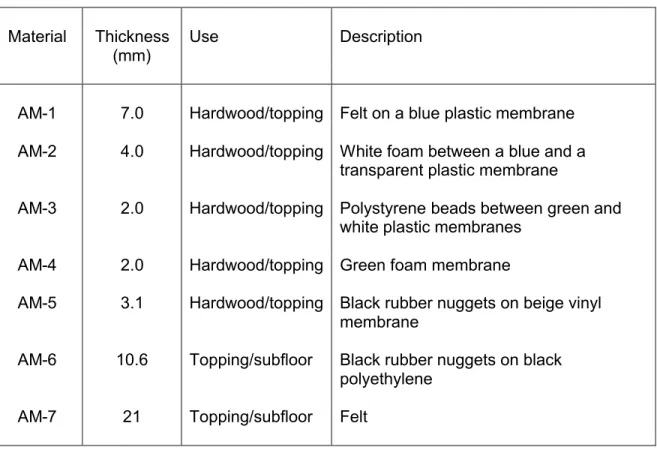
In this project, 5 acoustic membranes (AM-1 – AM-5) used between hardwood flooring and a concrete topping were tested as well as 2 materials (AM-6 and AM-7) used between a concrete topping and a subfloor. The materials were obtained from local suppliers and a brief description is provided in Table 1.
3 TEST METHOD AND SETUP
The cone calorimeter tests were conducted using typical acoustic membrane materials. These tests were conducted in general conformance with ISO 5660 [3] including the specimen holder and the data measurements specified in the test standard.
The specimens were 100 mm x 100 mm and were exposed to a 50 kW/m2heat flux. The test
specimen was mounted on a layer of ceramic fibre insulation and a grid1was used in all tests. A
single test was conducted for all the acoustic membrane materials except AM-4, for which duplicate tests were conducted.
1A common problem with fire test specimens is when they intumesce, either prior to ignition or during the burning. For most cases, a wire grid placed on top of the specimen can be used to minimize the effect on the measurements [4].
Table 1. Acoustic membranes tested.
Material Thickness Use Description
(mm)
AM-1 7.0 Hardwood/topping Felt on a blue plastic membrane AM-2 4.0 Hardwood/topping White foam between a blue and a
transparent plastic membrane
AM-3 2.0 Hardwood/topping Polystyrene beads between green and white plastic membranes
AM-4 2.0 Hardwood/topping Green foam membrane
AM-5 3.1 Hardwood/topping Black rubber nuggets on beige vinyl membrane
AM-6 10.6 Topping/subfloor Black rubber nuggets on black polyethylene
AM-7 21 Topping/subfloor Felt
4 RESULTS OF CONE CALORIMETER TESTS OF ACOUSTIC MEMBRANES
Cone calorimeter tests were conducted for seven acoustic membrane materials used in floor assemblies. A single test with a 50 kW/m2exposure was conducted for 6 samples. For the
seventh sample (AM-4), duplicate tests were conducted.
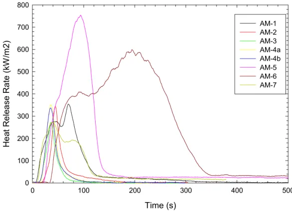
Plots showing the heat release rate, sample mass, rate of smoke release and effective heat of combustion are provided for each specimen in Appendix A and selected results are summarized in Table 2. The heat release rates for the materials are shown in Figure 1.
The five acoustic materials for use between hardwood flooring and a concrete topping ignited within 20 s, and flaming ceased in ≤ 200 s. I.e., the ignition time was ≤ 20 s and the flameout time was ≤ 200 s). The shortest ignition time (4 s) was for AM-1, which was a felt material on a blue plastic membrane. The thicker felt material (AM-7), which is to be used between a concrete topping and a subfloor, also ignited quickly (7 s) and sustained a flame for a short duration (206 s).
The other acoustic membrane material for use between a concrete topping and a subfloor (AM-6) had the longest time to ignition (32 s). It also sustained flames for the longest time (647 s). Materials AM-2, AM-3 and AM-4 each produced limited total heat outputs (each < 10 MJ/m2).
For comparison, the 2010 NBC [1] specifies that any building material can be used in a building required to be of noncombustible construction, with no limits placed on quantity or location, if it produces < 3 MJ/m2total heat release rate when tested in accordance with CAN/ULC S135 [5].
Materials AM-1 and AM-5 had total heat releases of 23.5 and 64.6 MJ/m2, respectively. These
two materials also had the highest peak heat release rates (354.3 and 753.7 kW/m2,
respectively) of the five acoustic membrane materials for use beneath a hardwood floor. The total heat release and peak heat release rate measured for acoustic membrane material AM-5 were significantly higher than the other four materials for use between hardwood flooring and a concrete topping. This material was selected for use in the large-scale apartment tests. For the two acoustic membrane materials to be used between a concrete topping and a
subfloor, material AM-6 had a significantly higher total heat release than AM-7 (159.2 and 21.2 MJ/m2, respectively). It was selected for use in the large-scale apartment tests.
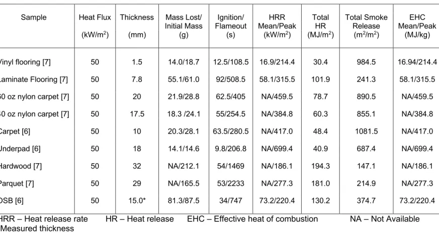
Table 3 shows cone calorimeter results for other typical materials used in floor assemblies [6, 7]. The total heat release and peak release rates for these materials are compared to those for the acoustic membrane materials in Figure 2 and Figure 3.
All the acoustic membrane materials except AM-5 and AM-6 had lower total heat release than the other flooring materials. Acoustic membrane material AM-5 had a total heat release
comparable to nylon carpets. Material AM-6 had a total heat release which was higher than the OSB and comparable to the other wood-based flooring materials.
Most of the acoustic membrane materials had peak heat release rates that were higher than the wood-based flooring materials and comparable to that produced by the carpets. However, materials AM-5 and AM-6 had considerably higher peak heat release rates than all of the flooring materials except that AM-6 was lower than the carpet underpad. These two acoustic membranes also had the highest total smoke release.
Table 2. Cone calorimeter results acoustic membrane materials*.
Sample Heat Flux Thickness Mass Lost/ Ignition/ HRR Total Total Smoke EHC Fuel Initial Mass Flameout Mean/Peak HR Release Mean/Peak Load (kW/m2) (mm) (g) (s) (kW/m2) (MJ/m2) (m2/m2) (MJ/kg) (MJ/kg) AM-1 50 7.0 7.5/10.0 4/159 151.4/354.3 23.5 394.9 27.7/50.0 20.8 AM-2 50 4.0 1.7/2.0 15/200 51.8/343.2 9.6 63.2 49.2/30.5 43.36 AM-3 50 2.0 1.4/1.7 10/129 55.1/271.8 6.6 132.5 42.3/24.9 34.7 AM-4a 50 2.0 3.2/7.0 12/74 40.5/351.1 9.3 103.6 25.2/27.1 11.7 AM-4b 50 2.0 3.1/6.7 11/77 126.6/336.5 8.4 100.6 24.2/13.0 11.1 AM-5 50 3.1 16.9/19.1 19/175 73.4/753.7 64.6 2084.6 33.8/49.7 29.9 AM-6 50 10.6 37.4/46.4 32/679 88.4/598.9 159.2 5188.4 37.7/49.9 30.4 AM-7 50 21.0 11.0/12.0 7/213 102.9/272.5 21.2 406.0 17.1/33.4 15.6
HRR – Heat release rate HR – Heat release EHC – Effective heat of combustion
Table 3. Cone calorimeter results for flooring materials.
Sample Heat Flux Thickness Mass Lost/ Ignition/ HRR Total Total Smoke EHC Initial Mass Flameout Mean/Peak HR Release Mean/Peak (kW/m2) (mm) (g) (s) (kW/m2) (MJ/m2) (m2/m2) (MJ/kg) Vinyl flooring [7] 50 1.5 14.0/18.7 12.5/108.5 16.9/214.4 30.4 984.5 16.94/214.4 Laminate Flooring [7] 50 7.8 55.1/61.0 92/508.5 58.1/315.5 101.9 241.3 58.1/315.5 60 oz nylon carpet [7] 50 20 21.9/28.8 62.5/405 NA/459.5 78.7 890.5 NA/459.5 40 oz nylon carpet [7] 50 17.5 18.3 /24.1 55/254.5 NA/384.8 60.3 855.1 NA/384.8
Carpet [6] 50 10 20.3/28.1 63.5/280.5 NA/417.0 48.4 1081.5 NA/417.0
Underpad [6] 50 18 14.1/14.6 9.8/206.8 NA/699.4 40.9 687.4 NA/699.4
Hardwood [7] 50 32 NA/212.1 54/1469 NA/186.1 194.3 147.1 NA/186.1
Parquet [7] 50 29 NA/165.5 53/2233 NA/277.3 181.0 214.9 NA/277.3
OSB [6] 50 15.0* 81.3/87.5 34/747 73.2/220.4 130.2 374.7 73.2/220.4
HRR – Heat release rate HR – Heat release EHC – Effective heat of combustion NA – Not Available *Measured thickness
Figure 1. Heat release rates for acoustic membrane materials.
Figure 2. Total heat release for flooring materials. Time (s) 0 100 200 300 400 500 H e at R e le a se R a te ( kW /m 2 ) 0 100 200 300 400 500 600 700 800 AM-1 AM-2 AM-3 AM-4a AM-4b AM-5 AM-6 AM-7 Flooring Material A M -3 A M -4 b A M -4 a A M -2 A M -7 A M -1 V in yl f lo or in g U nd e rp ad ( F P H ) C a rp e t ( F P H ) 4 0 o z ny lo n c a rp e t A M -5 6 0 o z ny lo n c a rp e t La m in a te F lo or in g O S B A M -6 P a rq ue t H a rd w o o d T ot al H ea t R el e as e ( M J/ m 2 ) 0 50 100 150 200 250
Figure 3. Peak heat release rates for flooring materials. 5 SUMMARY
A project, Wood and Wood-Hybrid Midrise Buildings, was undertaken to develop information to be used as the basis for alternative and acceptable solutions for mid-rise and taller building construction using wood structural elements. As part of this project, cone calorimeter tests were conducted to characterize seven acoustic membrane materials. The results of the cone
calorimeter tests are provided in this report. These results were used to select acoustic membrane materials for the floor assemblies used in the large-scale apartment tests. 6 ACKNOWLEDGMENTS
Financial and in-kind support for the project provided by the following organizations is gratefully acknowledged:
Canadian Wood Council
Forestry Innovation Investment BC FPInnovations
Ontario Ministry of Municipal Affairs and Housing National Research Council Canada
Natural Resources Canada
Régie du Bâtiment du Québec
Quebec government (Société d’Habitation du Québec, Société Immobilière du Québec, Ministère des Ressources Naturelles)Flooring Material H a rd w o o d V in yl f lo o ri n g O S B A M -3 A M -7 P a rq u e t La m in a te F lo o ri n g A M -4 b A M -2 A M -4 a A M -1 4 0 o z n yl o n c ar p e t C a rp et ( F P H ) 6 0 o z n yl o n c ar p e t A M -6 U nd e rp ad ( F P H ) A M -5 P ea k H ea t R el ea se R a te ( kW /m 2 ) 0 100 200 300 400 500 600 700 800
Extensive technical input by staff from collaborating organizations is also gratefully acknowledged:
Rodney McPhee and Ineke Van Zeeland, Canadian Wood Council.
Christian Dagenais, Mohammad Mohammad and Lindsay Osborne, FPInnovations. 7 REFERENCES
1. 2010 NBC, National Building Code of Canada, National Research Council, Ottawa, Ontario, 2010.
2. Su, J., Gover, B., Lougheed, G., Benichou, N., Swinton, M., Schoenwald, S., Lacasse, M., Di Lenardo, B., Mostafaei, H. and Pernica, G., Wood And Wood-Hybrid Mid-Rise Buildings, Phase 1: Scoping Study, B4726.1, National Research Council, Ottawa, Ontario, 2011. 3. ISO 5660-1, Reaction-to-fire tests – Heat release, smoke production and mass loss rate –
Part 1: Heat release rate (cone calorimeter method), ISO, Geneva, Switzerland, 2002. 4. Babrauskas, V., The Cone Calorimeter, in Heat Release in Fires, edited by Babrauskas, V.
and Grayson, S., Elsevier Applied Science, New York, 1992.
5. CAN/ULC-S135, Standard test method for the determination of combustibility parameters of building materials using an oxygen calorimeter (cone calorimeter), Underwriters’
Laboratories of Canada, Ottawa, Ontario, 2004.
6. Leroux, P., Kanabus-Kaminska, J.M., Séguin, Y.P., Henrie, J., Lougheed, G.D.,
Bwalya A.C., Su, J.Z., Bénichou, N. and Thomas J.R., Small-scale and Intermediate-scale Fire Tests of Flooring Materials and Floor Assemblies for the Fire Performance of Houses Project, Report IRC-RR-211, National Research Council, Ottawa, 2007.
7. Bwalya, A., Characterization of Fires in Multi-Suite Residential Dwellings: Cone Calorimeter Tests, National Research Council, Unpublished Data, Private Communication.
8 APPENDIX A – CONE CALORIMETER DATA FOR ACOUSTIC MEMBRANE MATERIALS
Cone calorimeter tests were conducted for seven acoustic membrane materials. For all except one material (Sample AM-4) a single test was conducted with a radiant exposure of 50 kW/m2.
For acoustic membrane AM-4, two specimens were tested, both with an exposure of 50 kW/m2.
In this Appendix, selected data plots are shown for each test: 1. Heat release rate (kW/m2),
2. Specimen mass (g),
3. Rate of smoke release ((m2/s)/m2), and
4. Effective heat of combustion (MJ/kg).
The effective heat of combustion is determined by dividing the heat release rate by the mass loss rate. Once the specimen mass reaches steady or near steady conditions, this can result in a small value being divided by a second small value, which can produce erroneous results. The data is included in the plots. However, the results after the test specimen reaches a steady or near steady mass should not be used.
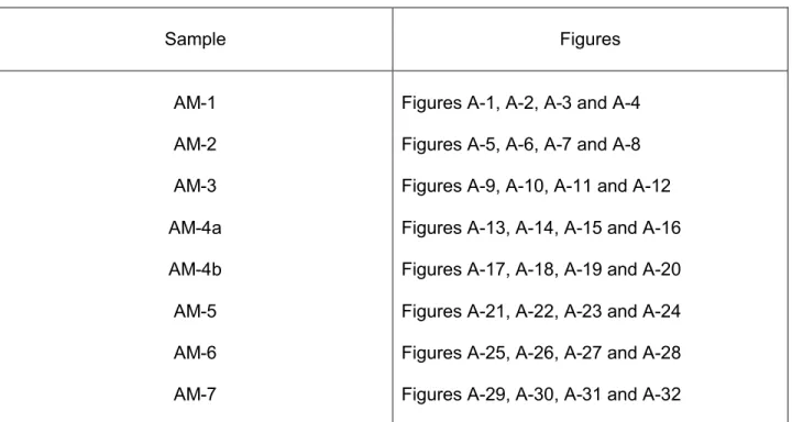
The list of the figures showing the data plots for each of the acoustic membrane samples are provided in Table A-1.
Table A-1. Figures showing plots for the acoustic membrane samples.
Sample Figures
AM-1 Figures A-1, A-2, A-3 and A-4
AM-2 Figures A-5, A-6, A-7 and A-8
AM-3 Figures A-9, A-10, A-11 and A-12
AM-4a Figures A-13, A-14, A-15 and A-16
AM-4b Figures A-17, A-18, A-19 and A-20
AM-5 Figures A-21, A-22, A-23 and A-24
AM-6 Figures A-25, A-26, A-27 and A-28
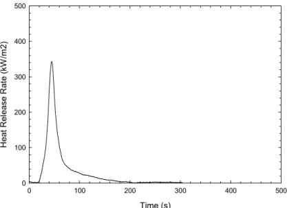
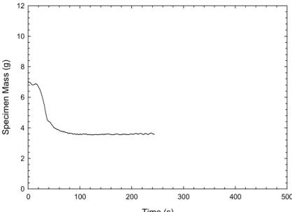
Figure A-1. Heat release rate - Sample AM-1. Figure A-2. Specimen mass - Sample AM-1.
Figure A-3. Rate of smoke release - Sample AM-1. Figure A-4. Effective heat of combustion - Sample AM-1. Time (s) 0 100 200 300 400 500 H ea t R el ea se R at e (k W /m 2 ) 0 100 200 300 400 500 Time (s) 0 100 200 300 400 500 S pe ci m en M as s (g ) 0 2 4 6 8 10 12 Time (s) 0 100 200 300 400 500 R at e of S m ok e R el ea se ( (m 2 /s )/ m 2 ) 0 2 4 6 8 10 12 Time (s) 0 100 200 300 400 500 E ffe ct iv e H ea t of C om b us tio n (M J/ kg ) 0 10 20 30 40 50
Figure A-5. Heat release rate - Sample AM-2. Figure A-6. Specimen mass - Sample AM-2.
Figure A-7. Rate of smoke release - Sample AM-2. Figure A-8. Effective heat of combustion - Sample AM-2. Time (s) 0 100 200 300 400 500 H ea t R el ea se R at e (k W /m 2) 0 100 200 300 400 500 Time (s) 0 100 200 300 400 500 S p e ci m e n M as s (g ) 0 1 2 3 4 5 Time (s) 0 100 200 300 400 500 R a te o f S m o ke R el e as e (( m 2 /s )/ m 2 ) 0 1 2 3 4 5 Time (s) 0 100 200 300 400 500 E ffe ct iv e H ea t of C om b us tio n (M J/ kg ) 0 10 20 30 40 50
Figure A-9. Heat release rate - Sample AM-3. Figure A-10. Specimen mass - Sample AM-3.
Figure A-11. Rate of smoke release - Sample AM-3. Figure A-12. Effective heat of combustion - Sample AM-3. Time (s) 0 100 200 300 400 500 H ea t R el ea se R at e (k W /m 2) 0 100 200 300 400 500 Time (s) 0 100 200 300 400 500 S p e ci m e n M as s (g ) 0 1 2 3 4 5 Time (s) 0 100 200 300 400 500 R at e of S m ok e R e le as e (( m 2 /s )/ m 2 ) 0 2 4 6 8 10 12 Time (s) 0 100 200 300 400 500 E ffe ct iv e H ea t of C om b us tio n (M J/ kg ) 0 10 20 30 40 50
Figure A-13. Heat release rate Sample - AM-4a. Figure A-14. Specimen mass Sample - AM-4a.
Figure A-15. Rate of smoke release - Sample AM-4a. Figure A-16. Effective heat of combustion - Sample AM-4a. Time (s) 0 100 200 300 400 500 H ea t R el ea se R at e (k W /m 2) 0 100 200 300 400 500 Time (s) 0 100 200 300 400 500 S pe ci m en M as s (g ) 0 2 4 6 8 10 12 Time (s) 0 100 200 300 400 500 R at e of S m ok e R el ea se ( (m 2 /s )/ m 2 ) 0 2 4 6 8 10 12 Time (s) 0 100 200 300 400 500 E ffe ct iv e H ea t of C om b us tio n (M J/ kg ) 0 10 20 30 40 50
Figure A-17. Heat release rate - Sample AM-4b. Figure A-18. Specimen mass - Sample AM-4b.
Figure A-19. Rate of smoke release - Sample AM-4b. Figure A-20. Effective heat of combustion - Sample AM-4b. Time (s) 0 100 200 300 400 500 H ea t R el ea se R at e (k W /m 2) 0 100 200 300 400 500 Time (s) 0 100 200 300 400 500 S pe ci m en M as s (g ) 0 2 4 6 8 10 12 Time (s) 0 100 200 300 400 500 R at e of S m ok e R e le as e (( m 2/s )/ m 2) 0 2 4 6 8 10 12 Time (s) 0 100 200 300 400 500 E ffe ct iv e H ea t of C om b us tio n (M J/ kg ) 0 10 20 30 40 50
Figure A-21. Heat release rate - Sample AM-5. Figure A-22. Specimen mass - Sample AM-5.
Figure A-23. Rate of smoke release - Sample AM-5. Figure A-24. Effective heat of combustion - Sample AM-5. Time (s) 0 100 200 300 400 500 H ea t R el ea se R at e (k W /m 2) 0 200 400 600 800 Time (s) 0 100 200 300 400 500 S pe ci m en M as s (g ) 0 5 10 15 20 Time (s) 0 100 200 300 400 500 R at e of S m ok e R e le as e (( m 2/s )/ m 2) 0 10 20 30 40 50 Time (s) 0 100 200 300 400 500 E ffe ct iv e H ea t of C om b us tio n (M J/ kg ) 0 10 20 30 40 50
Figure A-25. Heat release rate - Sample AM-6. Figure A-26. Specimen mass - Sample AM-6.
Figure A-27. Rate of smoke release - Sample AM-6. Figure A-28. Effective heat of combustion - Sample AM-6. Time (s) 0 100 200 300 400 500 H ea t R el ea se R at e (k W /m 2) 0 200 400 600 800 Time (s) 0 100 200 300 400 500 S pe ci m en M as s (g ) 0 10 20 30 40 50 Time (s) 0 100 200 300 400 500 R at e of S m ok e R el ea se ( (m 2 /s )/ m 2 ) 0 10 20 30 40 50 Time (s) 0 100 200 300 400 500 E ffe ct iv e H ea t of C om b us tio n (M J/ kg ) 0 10 20 30 40 50
Figure A-29. Heat release rate - Sample AM-7. Figure A-30. Specimen mass - Sample AM-7.
Figure A-31. Rate of smoke release - Sample AM-7. Figure A-32. Effective heat of combustion - Sample AM-7. Time (s) 0 100 200 300 400 500 H ea t R el ea se R at e (k W /m 2) 0 100 200 300 400 500 Time (s) 0 100 200 300 400 500 S pe ci m en M as s (g ) 0 5 10 15 20 Time (s) 0 100 200 300 400 500 R at e of S m ok e R e le as e (( m 2/s )/ m 2) 0 2 4 6 8 10 Time (s) 0 100 200 300 400 500 E ff ec tiv e H ea t of C om bu st io n (M J/ kg ) 0 10 20 30 40 50