MASSACHUSETTS INSTITUTE OF TECHNOLOGY ARTIFICIAL INTELLIGENCE LABORATORY
Working Paper 279 December 1985
Automated Program Recognition: A Proposal
by
Linda M. Zelinka
Abstract
The key to understanding a program is recognizing familiar algorithmic fragments and data structures in it. Automating this recognition process will make it easier to perform many tasks which require program understanding, e.g., maintenance,
modifica-tion, and debugging. This paper proposes a recognition system, called the Recognizer,
which automatically identifies occurrences of stereotyped computational fragments and
data structures in programs. The Recognizer is able to identify these familiar fragments
and structures even though they may be expressed in a wide range of syntactic forms.
It does so systematically and efficiently by using a parsing technique. Two important
advances have made this possible. The first is a language-independent graphical
repre-sentation for programs and programming structures which canonicalizes many syntactic
features of programs. The second is an efficient graph parsing algorithm.
Artificial Intelligence Laboratory Working Papers are produced for internal circulation, and may contain information that is, for example, too preliminary or too detailed for formal publication. It is not intended that they should be considered papers to which reference can be made in the literature.
Contents
1 Introduction
1
2 Program Recognition via Parsing
6
2.1 The Parsing Metaphor ...
...
12
2.2 Flow Graph Parsing ...
...
...
13
2.3 Parsing Plans ...
...
...
22
3
Applications of Program Recognition
39
3.1 Intelligent Tools ...
..
...
.
39
3.2 Computer-Aided Instruction ...
...
43
List of Figures
1 An Overview of the Program Recognition Process . ... . . . .... 2
2 Undocumented Common Lisp Code. .. . . .. ... ... . 6
3 Generating Textual Descriptions from the Recognizer's Output ... .. . 9
4 A Second Version of BBT-REF ... ... ... . .... . . 11
5 Another Instance of a Vector Reference . ... ... . 12
6 A Typical Flow Graph .... . ... ... 13
7 A Flow Graph Grammar ... . ... ... ... 15
8 A Derivation of a Flow Graph ... ... ... . 17
9 The Plan for BBT-LENGTH . . ... ... ... .. 19
10 The Plan of the Cliche Average . ... .... ... .... . 23
11 The Plan of a Program Which Contains Average ... ... 23
12 A Plan and a Subgraph of the Plan ... ... ... 25
13 Some Ways Joins can Associate ... ... .... 26
14 Control Environments ... ... .. 29
15 Sample Plan With Join... . . ... ... ... ... .. 32
16 Flow Graph Projection of Sample Plan ... ... 33
17 A Typical Grammar Rule with Constraints . ... ... 34
18 The Generation of All Possible Input Graphs . . ... ... . ... 38
1
Introduction
This paper proposes a system, called the Recognizer, which will perform automatic pro-gram recognition. Propro-gram recognition is the problem of automatically identifying oc-currences of familiar algorithmic fragments and data structures in a program. Given a program, the Recognizer will build a hierarchical description of the program's design, based on the stereotypic structures and fragments found.
The Recognizer's approach is based on a model of program understanding, called anal-ysis by inspection, developed by Rich [16]. The idea is that programmers (and engineers in general) do not attempt to understand a program (or any device) by collecting facts and proving theorems about it, except as a last resort. Much of the programmer's understand-ing comes from recognizunderstand-ing familiar parts and hierarchically buildunderstand-ing an understandunderstand-ing of the whole based on the parts. For example, a programmer may recognize that a bubble sort algorithm is being used to order the elements of a table. The table may be recognized further as having been implemented as a linked list of entries.
Performing this kind of recognition automatically is a difficult problem for several reasons. There are typically a variety of ways to syntactically express these structures in code. Some structures are diffuse in nature, requiring a global view of the code in order to find them. Recognition involves much searching.
As will be shown in the section on related work, most current approaches to the problem use techniques based on heuristics and deal with the program in its source code form. This severely limits the complexity and syntactic variability of the structures which are able to be recognized and the programs they can be recognized in.
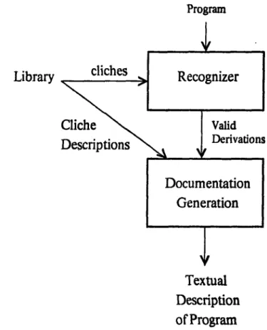
The Recognizer takes a different approach, shown functionally in Figure 1. The system treats program recognition as a parsing task. The basic idea is to convert the program into a graph representation, translate the library of familiar structures to be recognized into a grammar, and then to parse the program in accordance with the grammar.
This method is based on the idea that the stepwise refinement process used in pro-gramming can be modeled as a formal grammar derivation. Brotsky [1] drew an analogy between the implementation of high-level programming operations in terms of lower-level operations and the derivation of a graph by systematically replacing given nodes with
Program
Flow
Library of
Stereotypic
Structures
constraints
Valid
Derivations
Figure 1: An Overview of the Program Recognition Process
pre-specified subgraphs. If programs are represented as graphs and allowable implemen-tation steps are captured in grammar rules, then a parse of the program's graph provides a description of the program's top-down design.
As a first step toward applying the graph grammar metaphor to program recognition, Brotsky [2] developed a general-purpose graph parser which runs on a restricted class of labeled, acyclic, directed graphs, called flow graphs. His flow graph parser takes as input a flow graph and a flow graph grammar and determines whether or not the graph can be generated from the grammar. If it can, it gives all the possible derivations. The proposed research is concerned with the application of this parser to program recognition.
In order to use Brotsky's parser, the program must be treated as a flow graph and the collection of stereotypic structures must be treated as a flow graph grammar. This is made possible by a representation for programs which evolved from the Plan Calculus of Rich, Shrobe, and Waters ( [15], [16], [19], and [27]). This is a programming language-independent representation in which programs are represented as graphs, called plans. In a plan, nodes stand for operations and edges specify the data and control flow between them. Plans are quasi-canonical in the sense that they abstract away from how data and control flow are implemented. It doesn't matter which binding or control constructs are used in a program. Only the net data and control flow is shown in the arcs.
As is shown in Figure 1, a program is converted from source code to a plan by an analysis phase. The program is macro-expanded into a simpler language of primitive forms and then a control and data flow analysis is performed on the macro-expanded program.
The library of familiar structures must be translated into a flow grammar. Figure 1 shows that this is a manual translation. There is no intrinsic reason for the translation to be done manually. The same analyzer used in translating the program to a plan can be used if suitably extended. However, because of time constraints, the proposed system will have the library translated by hand into a grammar. This isn't a problem because this translation has to be done only once for the library to be used to analyze several programs.
Even when the program has been represented as a plan and the library as a grammar, recognition cannot be performed simply by parsing the plan in terms of the grammar.
There are two problems. The first is that the program plan is not a flow graph. There are several differences between the two representations. For example, plans may contain cycles while flow graphs are acyclic. Data flow arcs may fan out to several nodes within plans, but flow graphs cannot contain fan-in or fan-out arcs.
To make up for the differences between the two representations, some features, such as fan-in and fan-out, are dealt with by extending the flow graph formalism. Features of the Plan Calculus which cannot be handled by the extended parser, such as loops, are transferred to attributes on the nodes and edges of the flow graph. They are then dealt with by a reasoning mechanism which is separate from the parser.
In order to convert information into attributes, an intermediate translation stage oc-curs between the flow analysis and parsing stages. The graph which results from this translation contains a subset of the plan's nodes and edges. It is called the flow graph projection of the plan because it is a subgraph of the plan which contains some, but not all, of the information that the plan contains. The information it does not contain has not been discarded altogether. It is kept in the attributes of the flow graph.
The grammar rules which are induced by the stereotypic structures place constraints on these attributes. The constraint verification phase of the Recognizer filters out all successful parses which do not satisfy these constraints.
The second reason program recognition cannot be performed simply by running the parser on the program's plan is that programs cannot be expected to be constructed entirely out of familiar structures. There are bound to be unrecognizable sections in most large and complex programs. The recognition will therefore be partial. This means that parses may not always complete, but information can be gotten from subparses. (Nonterminals may be found, but not the top-level node.) This also means that parts of the program must be ignored. The Recognizer does this by running parsers at all points throughout the program graph. The parsing phase has a higher level control mechanism surrounding the flow graph parser to facilitate partial recognition.
The proposed research will focus on the following areas: * Developing the flow graph projection of the Plan Calculus.
* Adapting the flow graph parser to be able to parse this extended flow graph repre-sentation.
* Coordinating parses at all points throughout the program graph.
* Dealing with information which was converted to attributes in the translation from plan to flow graph.
Motivation
Understanding how a program is built out of stereotypic fragments is a prerequisite for being able to document, maintain, modify, and debug the program. Automating the program recognition process would, therefore, be helpful in making these tasks easier to carry out, both manually and automatically. This research is part of the Programmer's Apprentice (PA) project ([19], [20], [21], and [30]) whose goal is to design an intelligent software development system for assisting expert programmers in all aspects of program-ming. Many of the tools brought together in the PA will facilitate from the use of a program recognition module.
The Recognizer would also be very useful in the area of computer-aided instruction, since its ability to abstract away from the syntactic features of a program allow it to help deal with the great variability inherent in student programs. The ways that the Recognizer can benefit these applications will be discussed further after the Recognizer has been described in more detail.
Aside from its practical applications, program recognition is a worthwhile problem to study from a theoretical standpoint in the area of Artificial Intelligence. It is a step toward modeling how human programmers understand programs based on their accumulated programming experience. It is also a problem in which the representation of knowledge is the key to the efficiency and simplicity of the techniques used to solve the problem. Organization
Section 2 describes the problem of program recognition, giving the goals of the proposed recognition system and describing the parsing technique used to achieve them. This includes discussing the rationale behind using parsing, how flow graph parsing works, and what needs to be done to apply it to parsing programs. Section 3 shows how automatic program recognition can be put to use in a variety of applications. Section 4 discusses related approaches to automating the recognition process.
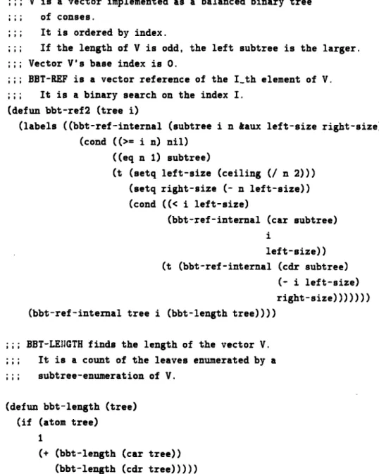
(defun bbt-ref (v i)
(labels ((bbt-refl (remaining-v index remaining-size) (cond ((>= index remaining-size) nil)
((eq remaining-size 1) remaining-v) (t (let ((lf-length
(if (evenp remaining-size)
(/ remaining-size 2)
(/ (+ remaining-size 1) 2))))
(if (>= index If-length)
(bbt-refl (cdr remaining-v)
(- index If-length)
(- remaining-size if-length))
(bbt-refl (car remaining-v) index lf-length))))))) (bbt-refl v i (bbt-length v)))) (defun bbt-length (v) (if (atom v) 1 (+ (bbt-length (car v)) (bbt-length (cdr v)))))
Figure 2: Undocumented Common Lisp Code
2
Program Recognition via Parsing
Suppose an experienced programmer were given the code shown in Figure 2 and asked to describe it. (The code is written in Common Lisp, as is all of the code in this paper.) In trying to understand the code, a programmer typically looks for familiar algorithmic fragments or data structures in it. These familiar structures are referred to as clichis.
In a typical analysis, a programmer may recognize that BBT-length is enumerating the elements of a binary tree of conses. The programmer can tell that it is also counting those elements enumerated which are on the fringe of the tree. The programmer recognizes this because a 1 is returned and accumulated every time an atom is encountered. Within
BBT-ref, the computation of If-length can be recognized as computing the ceiling of half of the remaining-size. Since this computation is used to determine which way to branch in the tree (to the left or to the right), the tree must be balanced and if its length is odd, the left subtree is larger than the right. The programmer can recognize that a binary search is being performed on index in BBT-ref from several clues. One is that the recursive call to itself is performed on the basis of whether index falls in the left or right subtree. Furthermore, when the tree is only one element in size, the element is returned as a result of the search. All the ways of dealing with trees shown in this piece of code are consistent with operations on vectors. This type of binary search on index suggests that this code is treating the tree as a vector and therefore the code for BBT-ref is performing a vector reference while BBt-length is finding the vector's length. The bound check for the index is a check that the index is greater than or equal to the size of the vector. This indicates that the vector's base index is 0.
As a result of this analysis, the programmer may come up with the following descrip-tion of the program:
The code treats the binary tree V as a vector. Vector V's base index is 0.
Vector V is implemented as a binary tree of conses, ordered by index and balanced. If the length of V is odd, the left subtree is the larger.
(BBT probably stands for "balanced binary tree".)
BBT-LENGTH finds the length of the vector by counting the leaves of the tree.
BBT-REF finds the Ith element of the vector V by a binary search on the index I.
The proposed system, called the Recognizer, is able to automatically perform a recog-nition process similar to the one just described. The Recognizer takes as input a program and a library of clich4s and finds all instances of the clich6s in the program.
To demonstrate the effectiveness of the analysis, the output of the Recognizer is pre-sented in the form of automatically generated program documentation. This documenta-tion is produced by a module which receives all valid derivadocumenta-tions from the Recognizer, as
is shown in Figure 3. The documentation module uses the technique, due to Cyphers [4), of associating with each cliche a textual explanation of itself. When a cliche is recognized, the explanation is used to generate text describing it. If given the code in Figure 2, the Recognizer will produce the following comments:
V is a vector implemented as a balanced binary tree of conses.
It is ordered by index.
If the length of V is odd, the left subtree is the larger. Vector V's base index is 0.
BBT-LENGTH finds the length of the vector, V. It is a count of the leaves enumerated by a subtree-enumeration of V.
BBT-REF is a vector reference of the I_th element of V. It is a binary search on the index I.
Some things to note about this documentation is that since the Recognizer does not understand natural language, some of the text will be awkward (e.g., "a count of the leaves enumerated by a subtree-enumeration of V"). Fixing awkward text will not be part of this thesis. Furthermore, the Recognizer cannot extract information from variable names or any comments the original program contains (e.g., it can't guess what the abbreviation BBT stands for).
Even though the documentation produced by the Recognizer is not as smooth as that written by the programmer, it describes the main features of the program's design. A desideratum for judging this output is for an experienced programmer to understand it easily.
The goal of the Recognizer is to be able to automatically analyze programs which contain straight-line expressions (i.e., ones containing no splits or joins), conditionals, single and multiple exit loops, recursion, and some data structures. The Recognizer cannot handle any side effects, except assignment to variables.
The library of clich6s given to the Recognizer will be a subset of an initial library of cliches which has been collected and formalized by Rich. The entire library cannot be used because some cliches contain side effects.
Program
Library
Textual
Description
of Program
The code used in the example of Figure 2 is contrived. The reason it is used is that it displays several of clich6s in a short example. It was given as part of a homework assignment in which the efficiencies of various side-effect free implementations of vectors were compared to each other. It displays more space efficiency than a list implementation does when an element is changed within the vector. Rather than copying O(n) elements to create a new updated vector, only O(log n) elements need to be copied. (Note that explaining what a piece of code is good for is not something the Recognizer is expected to be able to do, since that involves a much deeper understanding of the clich6s than is captured in the grammar.)
Recognizing Clich4s in Wide Classes of Equivalent Programs
One of the essential capabilities of the Recognizer is that it can recognize when two programs are equivalent at some level of design even though they may differ at a lower level. For example, the programs may differ syntactically (one using an if where the other uses a when), but the Recognizer will ignore these differences. The programs may also differ in the way a high level operation is implemented. The Recognizer will give the same -high level description of both of the programs. For example, one may use a hash table lookup while the other does a sequential search, but the Recognizer will point out that they are both performing a set member operation. The rest of the description for each program will be different, reflecting the differences in implementations on lower levels.
Figure 4 shows another version of the bbt-ref code which is different syntactically from the code in Figure 2. The Recognizer will yield the same analysis and textual description of the code as was given in Figure 2. Note that the two versions of bbt-ref differ in the control and binding constructs which are used, the binding of intermediate results, the way the index is compared to the size of the left branch ((> index If-length) versus
(< i left-size)), and the calculation of the size of the left and right branches.
The language-independent, canonical form into which the programs and clich6s are translated allows the recognition process to give the same description of both programs without being misled by the syntactic differences.
Some programs may also be seen as doing an equivalent operation even though they implement it in entirely different ways. For example, the code in Figure 5 can be seen as
;; V is a vector implemented as a balanced binary tree
;;; of conses.
;;; It is ordered by index.
;;; If the length of V is odd, the left subtree is the larger.
;;; Vector V's base index is 0.
;; BBT-REF is a vector reference of the I-th element of V.
;;; It is a binary search on the index I. (defun bbt-ref2 (tree i)
(labels ((bbt-ref-internal (subtree i n kaux left-size right-size) (cond ((>= i n) nil)
((eq n 1) subtree)
(t (setq left-size (ceiling (/ n 2))) (setq right-size (- n left-size)) (cond ((< i left-size)
(bbt-ref-internal (car subtree) i
left-size)) (t (bbt-ref-internal (cdr subtree)
(- i left-size)
right-size))))))) (bbt-ref-internal tree i (bbt-length tree))))
BT-LEi•TIn finas the length of the vector V.
It is a count of the leaves enumerated by a subtree-enumeration of V.
(defun bbt-length (tree) (if (atom tree)
1
(+ (bbt-length (car tree))
(bbt-length (cdr tree)))))
;;; V is a vector implemented as a list.
;;; It is ordered by index.
;;; LV-REF is a vector reference of the I-th element of V.
;;; It is a truncation of a list-generation of V by
;;; an integer count from I to 0.
(defun lv-ref (v i) (if (= i 0)
(car v)
(Iv-ref (cdr v) (- i 1))))
Figure 5: Another Instance of a Vector Reference
equivalent to that of Figures 2 and 4 when viewed on a high level of abstraction. They can both be seen as ways of doing vector references.
Viewing the design of programs on different levels of abstraction is an important capability for the Recognizer to have. The analogy between the hierarchical decomposition of programs and flow graph derivation is the key to having this ability. The next section will explain this analogy and discuss why it is an appropriate metaphor for recognition.
2.1 The Parsing Metaphor
A good way to explain the hierarchical design of a program is to take a top-down approach. Higher level operations can be described as being implemented in terms of lower level operations on each successive level of abstraction. This is directly analogous to a flow graph derivation process wherein a set of rewriting rules, called a flow graph grammar, are used to specify how given nodes can be replaced by specific subgraphs. In this analogy, flow graphs correspond to graphical abstractions of programs, flow grammars specify allowable implementation steps, and the resulting parse tree gives the top-down design.
Flow grammars derive flow graphs in much the same way as string grammars derive strings. The flow graph parsing process is simply a generalization of string parsing. All characteristics of standard context-free grammars for deriving strings apply.
Figure 6: A Typical Flow Graph
left hand side of each rule is a single node which gives a more abstract description of the right hand side graph. If the rules were context-sensitive, they would be specifying program transformations in a wide-spectrum language, rather than specifying implemen-tation relationships. In program transformations, instead of a single node, the left hand side is typically another graph which specifies a series of substitutions or modifications to be made to the graph being parsed.
It is important to note that no claims are being made that programmers actually program by having a grammar in their heads which they use to design (i.e., derive) a program. Nor do they use a grammar to parse programs in their attempt to understand them. A grammar is simply a useful way to encode the programmer's knowledge about programming so that, by parsing, standard ways of using the knowledge can be recognized more easily.
The key to being able to raise parsing from being simply a metaphor to being a technique for recovering a top-down design of a program is the representation of programs used. This point will become clearer once the Plan Calculus and flow graph representations and the clich6 library are described in more detail.
2.2 Flow Graph Parsing
A flow graph is a labeled, acyclic, directed graph with the following restrictions on its nodes and edges.
1. Each node has a label, called its type.
2. Each node has input ports and output ports. (Ports are positions at which edges enter or leave a node.) Each port is labeled. No port can be both an input and an output port. There are the same number of input and output ports on all nodes of the same type.
3. There is at least one input and one output port on each node.
4. All edges run from a particular output port of one node to a particular input port of another. No port may have more than one edge entering or exiting it. Therefore, a node can be adjoined by at most as many edges as it has ports.
The key restrictions to note are the third and fourth. The third outlaws sources and sinks, i.e., nodes which have empty input or output port sets, respectively. The fourth restricts edges from fanning into or out of a port. These will be particularly relevant to the discussion of what needs to be adapted in order to parse a program's graph, since this graph may contain edges fanning in and out, and sinks and sources.
Some further characteristics of flow graphs are that ports need not have edges adjoining them. Any input (or output) port in a flow graph that does not have an edge running into (or out of) it is called an input (or output) of that graph.
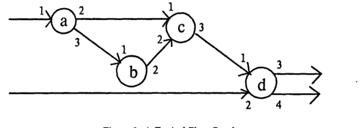
An example of a flow graph is given in Figure 6. The ports have been labeled with numbers so that they may be referred to. The inputs to the graph are port 1 on node "a" and" port 2 on node "d". The outputs are ports 3 and 4 on node "d".
The flow graph in Figure 6 can be derived from the flow graph grammar shown in Figure 7. A flow graph grammar is a set of rewriting rules each specifying how a node in a graph can be replaced by a particular subgraph. All rules in a flow grammar map a single left hand side node to a right hand side graph. The left hand side node is of a nonterminal node-type, while the right hand side graph can contain nodes of both terminal and nonterminal types. (Nonterminals are denoted by capital letters, while terminals are in lower case.) There is a one-to-one correspondence between the inputs of the left hand side and the inputs of the right hand side of each rule; the same holds for the outputs. This means that the arity of the left hand side and the right hand side must be equal.
-4
" N N --h N - N / /B
N - NFigure 7: A Flow Graph Grammar
\
J
A sample derivation of Figure 6 in accordance with the grammar of Figure 7 is given in Figure 8.
Since flow graph parsing can be seen as a generalization of string parsing, Brotsky de-veloped an algorithm which generalizes Earley's string parsing algorithm [6]. The behavior of a non-deterministic stack-based parser is deterministically simulated by his algorithm. The simulation essentially allows several graph parsers to run in parallel, each eventually coming up with a different guess as to the derivation of the input. Thus, all possible parses of the input are obtained. The way that this is done is by having a read head march over the input graph in one pass, scanning all nodes and edges exactly once. For each node scanned in the input, the algorithm generates all reachable configurations of all parsers being run on the input. Since these parsers are collectively simulating a single nondeterministic parser, the set of all possible configurations of the deterministic parsers can be seen as all the configurations the nondeterministic parser might be in, given the nodes that were scanned in the input graph.
The reachable configurations at each step are kept track of in item lists. Each item has associated with it a grammar rule which is being applied to the input being scanned. The item has information about where in the right hand side of the rule the read head is in relation to the read head in the input graph. Any nonterminal in the right hand side of this rule causes separate sub-items to be activated for each rule which derives that nonterminal. When a node is scanned in the input graph, the read head steps over it. The corresponding read head is also stepped in all active items. (This is a much simplified description of the parsing algorithm. The actual operation of the parser is much more sophisticated and optimized. Consult 12) for more information.)
Because the algorithm is agenda-based, i.e., it works by consulting and updating the current item list, its behavior can be controlled simply by altering this list. This is one of the key strengths of the parser which allows it to be adapted and applied to the problem of program recognition.
Some of the other good reasons for applying the flow graph parser to recognition are that it is efficient and that it works. The algorithm runs in time polynomial in the number of nodes in the input graph. Brotsky provided a working implementation of the algorithm written in Lisp.
Figure 8: A Derivation of a Flow Graph 17
The Plan Calculus
The representation of knowledge has a direct effect on how easy or hard it is to carry out a complex operation on the knowledge. In trying to perform the task of automatic program recognition, this is certainly the case. The Plan Calculus makes the recognition task much easier and more straightforward. It allows programs to be represented as graphs and the clich6 library as a grammar, making them more amenable to a parsing technique. The Plan Calculus representation is also valuable because it abstracts away from the syntactic features of a program, allowing the program's algorithmic structure to be emphasized. The complex task of program recognition is thus made easier by allowing syntax issues to be ignored.
A program is represented in the Plan Calculus as a graph, called a plan, in which nodes represent operations and edges explicitly show the control and data flow between them. As an example, Figure 9 shows the plan representation for the bbt-length function which is part of the program given in Figure 2. As is shown in the figure, there are two types of edges in plans: one indicating data flow and the other control flow. (When a graph is drawn, control flow edges are denoted by cross-hatched lines, while data flow edges are simply solid lines.) Branches in control flow corresponding to a conditional are represented by nodes, called splits, which have one control flow input arc and two control flow output arcs, one for each of the cases of the split (true or false). The type of a split node is null?. The test to see if an object is null is the only primitive predicate in Lisp. In other languages, there may be more types of primitive tests and therefore more types of splits. A merging of control flow and data flow (e.g., to obtain the return value of a conditional), is represented by a join. These are boxes which have two or more control flow arcs coming in. A recursive call to a function is represented as a node with the name of the function as its operation type. A loop may be represented in the Plan Calculus as a tail-recursion or as a cycle in control flow and data flow arcs.
In the Plan Calculus, all syntactic information about what types of binding or control constructs are used is abstracted away. It doesn't matter if one program uses cond while another uses if, for example, or if one binds intermediate results in variables while another passes all data through nested expressions. If all the data flow is coming from matching places in each program and the same operations are performed on the data, the plans for the programs will be equivalent in terms of data flow. This is because the representation
BBT-le
Figure 9: The Plan for BBT-LENGTH
shows net data flow. Net control flow is represented also, so that the particular control flow constructs used by the program are abstracted away, making it easier to compare two programs. However, two equivalent programs might not have the same plan because some of the control flow information of the plan is not canonicalized enough. As will be shown, this is-the main source of trouble in trying to apply parsing to recognition.
The Flow Analyzer
The module within the Recognizer which converts a program from source code to a plan is the Flow Analyzer. The method of translation is borrowed from the analysis techniques employed by KBEmacs
[301,
the most recent demonstration system implemented as part of the Programmer's Apprentice project. The translation is done in two stages: macro-expansion followed by control and data flow analysis.The macro-expander translates the program into a simpler language of primitive forms. It also selectively flattens parts of the program by open-coding functions and procedures inside their callers. It does not automatically flatten the entire program because for some cliches this is not necessary. For efficiency reasons and also because recursive functions cannot be completely open-coded, the flattening process is restrained. The selection of what should be flattened and at what time is under the control of the user, since it is in general hard for the Recognizer to make these decisions automatically.
The control and data flow analysis is performed by a symbolic evaluation of the pro-gram. The evaluator follows all possible control paths of the program, converting tions to nodes and placing edges corresponding to data and control flow between opera-tions. Whenever a branch in control flow occurs, a split is added. Similarly, when control flow comes back together, a join is placed in the graph and all data representing the same variable is merged together.
The graph that results from the flow analysis is called a surface plan, since it is only a more canonical, language-independent form of the program. It contains no deeper knowledge about the program.
The flow analyzer used by the Recognizer translates Lisp programs into plans. Similar analyzers have been written for subsets of Cobol, Fortran, and Ada ([191, [7), [27], [30]), but for simplicity will not be used in this system.
The Clichi Library
The clich6 library specifies implementation relationships between plans. These relation-ships give the library a hierarchical structure. There are two types of hierarchical structure which must be captured by the grammar rules used by the Recognizer.
The first type of structure is expressed by clich6s which relate a single high level operation or data structure to a group of lower level ones from which it is constructed. For example, the plan for the list-length clichd maps the abstract operation of finding the length of a list to a possible implementation of that operation. The plan for list-length induces the following rule:
SEE FIGURE NEXT PAGE
In general, the left hand side of the rule is a single node whose type is the name of the operation being implemented by the plan and the right hand side is the graph which gives a possible implementation.
The second type of hierarchical structure inherent in the clich6 library is expressed by implementation overlays within the library. These relate a single operation or data structure to another single operation or structure. They represent a shift in the way an operation or structure is viewed by a programmer. For example; a typical overlay is list-length>set-cardinality (read as "list-length as set-cardinality") which specifies that a list length operation can be viewed as an operation to find the size of a set, given that
list
List-Length
integer
integer
the input set is implemented as a list. The list-length>set-cardinality overlay induces the following rule:
set
\
list
Zr>
List-Length
integer
\
/
integer
It is simply a re-writing from a single node to another node. The important differences between the left and right hand sides of the rule are the types of the nodes and the type of data objects being operated on. These differences reflect the differences in the way the programmer views these operations and data structures between levels of abstraction. When an overlay-induced rule is used in the parse of a program, it uncovers a design decision to implement a certain abstract data type as a lower level data type.
2.3
Parsing Plans
Once the program is represented as a graph (i.e., as a plan), and the library of clich6s is
translated into a grammar, parsing can be applied as a technique for program recognition.
The parsing process finds those subplans within the program's plan which are clich6s inthe library. This means it finds subgraphs of the program's graph which match the right
hand sides of rules in the grammar. A fundamental part of parsing, then, is subgraph
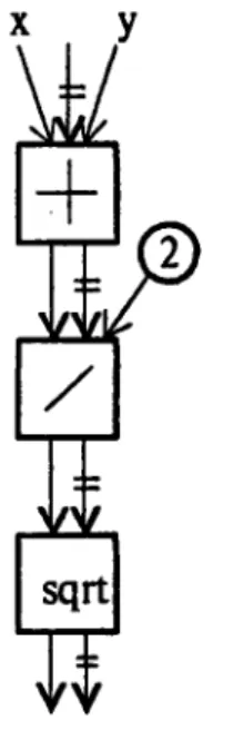
matching. For example, one of the simple straight-line clich6s in the library is the clich6average. It computes the average of two input numbers. Its plan is shown in Figure 10.
The following (contrived) program contains the average cliche.
Figure 10: The Plan of the Clich6 Average
(defun sqrt-avg (x y) (sqrt (/ (+ x y) 2)))
The plan for sqrt-avg is shown in Figure 11. It contains average's plan as a subgraph. This forms a structural handle for the right hand side of the grammar rule induced by the clich6 average. The code corresponding to this subgraph can then be pointed out as a clich6 within the program.
Why Subgraph Matching Cannot Be Used Directly on Plans
Performing subgraph matching directly on plans does not always lead to the recognition of all the clich6s which occur in a program. There are two major problems. Both stem from the fact that the Plan Calculus does not canonicalize some control-flow-related aspects of the program enough. In particular, even though it is able to abstract away from which constructs are used in a program to implement control flow, it is too rigid in representing the order of execution of operations and how joins merge data and control flow. The result is that two programs may be equivalent but have different plans. This is a major obstacle to the use of subgraph matching to compare two plans.
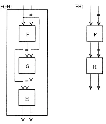
There are two problems with the Plan Calculus representation which hinders subgraph matching. First, it fails to capture the transitivity of control flow. Second, it doesn't treat joins as being associative.
As an illustration of the first problem, that transitivity of control flow is not repre-sented, consider the graphs in Figure 12. The smaller graph to the right ("FH") is a subgraph of the larger one ("FGH") which is the plan for the following function.
(defun FGH (x) (let ((z (F x)))
(G x) (H z)))
However, this subgraph cannot be found because it does not match exactly with FH. There is a control flow arc missing between the f and h nodes. By transitivity of control flow, there is control flow between the two nodes, but the plan does not show it explicitly.
FH:
Figure 12: A Plan and a Subgraph of the Plan
Figure 13: Some Ways Joins can Associate 26
The second major problem with the Plan Calculus is that it doesn't treat joins as being associative. Joins, when nested, can associate in a variety of ways. For example, all of the plans shown in Figure 13 are equivalent, since joins are associative. Yet they do not structurally match each other.
Expressing Transitivity of Control Flow
In order to solve the transitivity problem, the transitivity of control flow must be rep-resented in the Plan Calculus explicitly. One way to do this is to transitively close the entire plan with respect to control flow. This is an expensive computation, however. The extra control flow arcs bring added complexity to the graph and increase the graph's space requirements. Furthermore, the transitive closure computation is made more complicated by sections of the plans which contain splits and joins and which need to be treated spe-cially. In particular, all sections of a plan which have splits and joins at either end must be treated as a single node when closing the rest of the graph. Within the split-join section, each branch of the split must be transitively closed independently.
Rather than doing this expensive computation, the method chosen is to remove control flow arcs from the plan altogether and represent the information that they contain in a simpler, more manageable and space efficient form. Control flow arcs specify two types of information. One is the order of execution of operations which was chosen by the programmer. This order is irrelevant to the recognition process, since the only order between the operations which must be the same in two equivalent plans is that imposed by data dependencies. Data flow arcs provide this structural constraint.
The second type of information which control flow arcs provide is that they group together operations which are in the same control environment. Control environments tell under which conditions operations are performed. Each operation contained in a control environment is performed the same number of times as every other operation in that control environment. That is, all operations in a control environment co-occur. The co-occurrence relation specifies the transitivity of control flow between operations.
All operations in a straight-line expression co-occur. When control flow splits, two new control environments are created, one for the true side and one for the false side of the split. Each branch of the split is in a separate, unique control environment. Splits are
different than operations in that they have two extra attributes, success-ce and failure-ce which specify the control environments of the two sides of the conditional.
The control environments form a partial order. The order relation is less than. A control environment, ce2, is less than another control environment, cel, if operations in ce2 are performed fewer times than those in cel. Control environments of opposite branches of a split are incomparable. For example, in Figure 14, all operations are annotated with a control environment (in the form "ce" with a unique number). In the figure, ce4 is less than ce2, while ce3 and ce4 are incomparable.
By placing attributes on nodes which tell which control environment the nodes are in, control flow arcs can be done away with. The crucial information they carry is converted to a form which can be dealt with separately from subgraph matching (and therefore parsing).
The separate mechanism used is a constraint verifier which works as follows. Associ-ated with each grammar rule is a set of constraints. Once the parser is run, the constraint verifier completes the recognition by checking all successful parses to be sure that the control flow constraints of the rules that were applied are satisfied. A successful parse is thrown away if the nodes and edges involved in the input program graph do not obey the control flow constraints. The verification of constraints is actually folded into the parsing process for efficiency. At each parse step, the constraints are checked so that if any fail to hold, the parsing will be cut off earlier. In this way, the parser acts as a first filter of possible subgraphs that may be recognized as clich6s. If a subgraph does not pass the parser without the control flow information, it would not have passed with the additional information either.
success-ce:
ce2
failutre-ce:
ce5
Figure 14: Control Environments
:e.
node. In the FGH example, if FH were the plan for a clichM, the grammar rule would be
?+
constraint:
F and H
•H
co-occur
The clich6 FH would be found and the constraint that F and H be in the same control environment would be satisfied. Thus, the clich6 FH would be recognized in FGH.
Expressing Associativity of Joins
The problem of representing the associativity of joins is solved using the same attribute-constraint mechanism which is employed in solving the transitivity problem. Again, in-formation is removed from the plan and placed in attributes. In particular, all joins are removed from the plan, causing all data flow arcs merged by the join to fan into operations which received the merged data flow coming out of the join. The information joins pro-vide specifies, for each incoming data flow arc, in which control environment is data being carried by that particular arc. For example, the join in Figure 15 specifies that when the true side of the split is taken, b will receive data flow from the negate node and when the false side is taken, it will receive data flow from a. This information is converted into attributes on the edges of the graph which are being merged. The attribute on each edge simply tells in which ce the edge carries data flow. For instance, the plan in Figure 15 becomes the annotated flow graph in Figure 16 when the joins and control flow arcs are removed.
The typical constraint placed on an attributes of an edge is that data flow be carried on that edge in a particular control environment. For example, the grammar rule induced by the absolute value clich6 is shown in Figure 17. (The constraints are given informally to avoid describing the syntax of how they are specified.)
Note that the associativity of joins is expressed by allowing the data flow arcs which are being merged to fan in and thus associate in all possible ways. No particular way of associating (e.g., that all joins must associate to the left) must be enforced in order to canonicalize the graph.
In summary, determining whether two plans are equivalent cannot be done simply by matching them against each other. Therefore, subgraph matching alone cannot be used as the heart of parsing. Some of the information in plans is converted to annotations on the plan's nodes and edges. What is left is a flow graph (called the flow graph projection of the plan). Two plans are equivalent, then, if their flow graph projections match and their attributes are logically equivalent. The core operations of parsing are subgraph matching (of flow graphs) and logical subsumption (of attribute values).
ries data
:e3
I
Figure 16: Flow Graph Projection of Sample Plan 33
Figure 15: Sample Plan With Join
Constrain
1. Data fic
from negate node in
the success-ce of null?
2. Data flow out comes
from input in
the failure-ce of null?
Figure 17: A Typical Grammar Rule with Constraints 34
The key features of the attribute-constraint mechanism are its simplicity and gener-ality. It is a uniform way to solve two different problems. It is less expensive in terms of time to compute, algorithmic complexity to manipulate, and space required to store the information provided by joins and control flow arcs.
There is a tradeoff between how much information should go into attributes versus into the graph. If too little information is in the graph, a tremendous number of parses may be generated, since the structural information is less specific and constraining. The burden would then be on the verifier to weed out the valid parses. On the other hand, if too much information is in the graph, the parsing process may become too complicated.
For example, if the transitive closure of the plan were represented in control flow arcs, the graph to be parsed would be much larger and more complicated than the flow graph with control environment annotations.
Other Obstacles to Recognition via Parsing
There are still a few difficulties with running a flow graph parser on program plans - even flow graph projections of plans - in order to recognize cliches. One problem is that the flow graph projections of plans have characteristics which cannot occur in the flow graphs given to the parser. These include:
* fan-out arcs - the results of an operation may be shared by two or more operations,
a situation represented as edges fanning out of a single node; * fan-in arcs - the removal of joins causes data flow arcs to fan in; * sources - splits have no output ports;
* sinks - programs use constants which become source nodes;
* cycles and recursive nodes - programs contain recursion, including tail recursion (or loops), while flow graphs are acyclic and input graphs to be parsed may not contain recursive nodes.
Another obstacle to performing program recognition via parsing arises from the fact that programs (particularly large ones) typically cannot be analyzed entirely in terms of cliches. There will usually be parts which are not familiar. The Recognizer must be able to ignore sections of programs in order to recognize clich6s in other sections.
Jumping the Hurdles
The way the proposed Recognizer overcomes the difficulties of the type described in the previous section is by working at the problems from three angles:
1. extend the capabilities of the parser as far as possible,
2. convert to attributes any features of plans which the extended parser still cannot deal with and use constraint verification to deal with this information separately, and
3. provide higher level mechanisms for starting multiple parses throughout the input program graph and for dealing with recursion.
Extending the Flow Graph Parser
The parser is being extended to handle fan-in and fan-out edges, and source and sink nodes. The modifications made to handle sinks and sources are changes to the internal mechanisms which allow the read head to scan nodes. For edges to be able to fan in or out in the input graph or in the grammar rules' right hand sides, alterations are made to the item-lists as the parser is running. A discussion of exactly how the parser is modified would require taking a plunge too far into the implementation details. The important point is that aside from modifications extending the types of nodes and edges the parser expects to be manipulating, the modifications are simply ways of altering the parser's explicit agenda. This is what makes it feasible and easy to make such global extensions as allowing edges to fan-in and fan-out.
Loops and Recursion
Loops are dealt with by breaking any arcs which feed back in the plan and simply parsing the loop body. The feedback arcs and control environment information of the loop can then be dealt with separately using the attribute-constraint facility.
The details of how to handle recursion in general have yet to be worked out. It is anticipated that the research into recognizing clich6s containing loops will provide insights into how to deal with recursion in general.
Partial Parses
The problem of supporting partial recognition is dealt with by a higher level mechanism which oversees and controls the flow graph parser. In order to find familiar features in the midst of unrecognizable parts of the program, parses are started at all points throughout the input graph. This allows parts of the program to be skipped or ignored. The Recognizer coordinates multiple parses throughout the program graph. This involves essentially running the flow graph parser on several different input graphs. (For efficiency, the input graph will actually be shared by the various parsers.) The graphs are generated by systematically making all possible cuts through the input graph. For each cut, all combinations of the edges on the cut are found. The size of each combination is the number of inputs the top-level (S) node of the grammar has. (This is because the S-node is to have the same arity as the input graph in order to be matched with it.) Each combination found is treated as the set of input edges of a graph to be parsed. This causes
another level of input graphs to be generated.
Figure 18 shows this generation of all possible input graphs from a single graph. Level A shows the original graph, with all possible cuts indicated by vertically snaking lines. Level B shows some of the versions of the input graph which are represented by the cuts of Level A. Level C shows the combinations of input edges which would be produced for the version of the input graph given by the second cut. (The input arity of the S-node of the grammar is two.)
Level A:
- -~~/ -~
*so
Figure 18: The Generation of All Possible Input Graphs
3
Applications of Program Recognition
Automatic program recognition has applications in at least two main areas. First, it makes possible a set of new AI-based software development and maintenance tools. Their effectiveness comes from their deep understanding of the programs to which they are applied. A second domain in which recognizing a broad range of programs is useful is computer-aided instruction. This section discusses the ways the Recognizer can be incorporated into software development and maintenance tools and into a programming tutor.
3.1 Intelligent Tools
An analysis system supporting program recognition will be an essential part of the next demonstration system of the Programmer's Apprentice (PA) project ([19], [20), [21], and (30]). The PA is an intelligent software development system designed to assist expert programmers in all aspects of programming. Many of the tools provided by the PA will benefit from the use of a program recognition module. This section points out some of the tools for which program recognition is expected to be useful.
Documentation
The ability to recognize familiar constructs in code allows automatic generation of docu-mentation to explain these parts and how they fit together. This description will reflect a deep understanding of the program's behavior and structure, rather than simply giving the program's syntactic features, such as the number of arguments it has.
Cyphers [4] shows how explanations can be attached to clich6s so that when they occur in a program, automatic documentation can be generated based on the program-ming knowledge they contain. The documentation module which is used to demonstrate the Recognizer's output takes basically this approach. It gives as output an English de-scription of the parse trees generated by the parsing process. For each high level clich6 recognized, the system generates a textual, hierarchical description of the code containing the clich6 and any subclich4s involved. The description is generated on the basis of the documentation strings included in the cliche's definitions and the details of the parse.
Verification
Rich [161 discusses the applicability of program recognition to verification. Clich6s can be pre-verified in the sense that fragments which programmers use over and over usually have been tested and their behavior is predictable. Because of this, recognizing cliches in code can increase the programmer's confidence in the code. There is also ongoing work on formally pre-verifying clich6s [18], [17].
Debugging
The recognition system can be incorporated into a debugging tool, giving the debugger the ability to both find specific bug clichis and to do near-miss recognition [16]. Searching the code for specific bugs is the way most current debugging systems work (e.g., [22], [11], [25], [23]). This is useful when bugs are treated as explicit entities which have information attached, such as advice or bug-fixes. Rich, on the other hand, points out the usefulness of near-miss recognition in debugging. In near-miss recognition, clich6s which are almost correct are pointed out as potential errors. For example, near-miss recognition can point
out that a clich6 can almost be recognized except that
* a particular operation was not performed or a subclich6 was not recognized and therefore the larger one could not be found;
* the wrong operation was done on the correct data and the right thing was done with its result;
* arguments to a procedure or function were given in the wrong order; * the arms of a conditional are switched;
* the return value of a piece of code is coming from the wrong place.
* a superfluous operation is performed within a program fragment in which a clich6 was expected to occur.
An advantage of this type of error detection is that it does not require having to catalog all possible wrong versions of a clich6 in order to be prepared to recognize and intelligently
explain a bug. Note that a number of near-misses can be recognized by collecting those parses which pass graph matching but fail some control flow constraint.
In both debugging techniques, automatic program modification to fix bugs is made easier by program recognition. Bug clich6s are "pre-debugged" in that their fix can be included in the information associated with them. Likewise, near-misses of clich6s can be replaced by a correct version.
Shapiro's Sniffer [23] is an example of what is possible using program recognition in debugging. His clich6-finders do a kind of program recognition using exact match. Sniffer relies on the fact that the programs being debugged can be represented using a single clich6 with little or no variation in the roles and subclich6s. For larger algorithms, subclich6s can be implemented in a variety of ways. This poses a problem for Sniffer, but it is very easy to deal with using flow graph grammars. Flow grammars are able to capture several implementations for the same higher level operation on any level of design. Thus, the generality of the clich6-finders would be increased by the more powerful parsing technique used by the recognition system.
Translation
Translation is the process of converting a program in one language into another. This is usually for the purposes of making the program more efficient (as does compilation) or making it more readable (as does source-to-source translation). Being able to recover the top-down design tree of a program coded in the source language facilitates the automatic rewriting of the design in the target language (see Waters [31]). Faust [7] shows the feasibility of this approach to source-to-source translation in order to relieve the burden of understanding on the part of the maintainer. He built a prototype system which takes COBOL programs, converts them to the plan representation, and then abstracts them onto a higher level by analyzing them in terms of Plan Building Methods (PBMs) [27), [281. The analyzed program is then converted into HIBOL, a high level language for data processing applications. Faust's system is limited by the special-purpose techniques it uses to recognize specific features of COBOL programs. The system could benefit from a general program recognizer which would broaden the class of programs that could be translated.
Maintenance
The key to being able to maintain a program is being able to understand it. Translation and documentation generation are two ways discussed so far wherein automatic program recognition can help increase a maintainer's understanding of code. Another way is that analysis based on program recognition can generate more informative explanations about what can be expected to happen if a certain change is made to the code. The explanations are in the programmer's vocabulary and relevant pieces of code can be pointed out.
3.2
Computer-Aided Instruction
Program understanding is essential in the domain of computer-aided instruction of pro-gramming. Besides simply giving a student pre-stored exercises to solve, a programming tutor must have an understanding of what the student's solution is supposed to achieve. It must be able to recognize whether or not the student's code does achieve that goal in order to check the correctness of it and debug it. An important part of this is being able to deal with great variability in acceptable solutions. The tutor should not be dis-tracted or thrown off by extra activity, such as print statements, or by bugs which cause. unrecognizable sections of code.
This section gives a description of how program recognition can be applied to com-puter-aided instruction which is more detailed than the discussions of other applications. This is because the tutor takes advantage of most of the capabilities of the Recognizer. Two of the most important are its ability to deal with broad classes of equivalent programs and to perform partial recognition when parts of the code are not familiar or are buggy. The tutor also uses some of the applications described earlier. A design for the tutor is given in this section to show more specifically the role the Recognizer would play in such an application.
Overview
Figure 19 gives a block diagram of a recognition-based tutoring system. The tutoring system interacts not only with the student, but also with the teacher who is developing the curriculum.
The ways the tutor interacts with the teacher are the following. The system allows the teacher to set up exercises for the student to solve. For each exercise, the teacher gives a problem statement and a grammar defining a top-down design of a typical solution. The grammar corresponding to the teacher's solution is mapped to the problem statement in the exercise bank.
The top-level rule given by the teacher simply maps an exercise name to a plan which implements its solution. However, most of the rules in the grammar specify clich6s. These may be used in several of the teacher's solution designs. Rather than duplicating much of the grammar rules each time a solution grammar is given, the teacher may maintain a library of rules which specify cliches and which may be used in several solution designs.