HAL Id: tel-00712072
https://tel.archives-ouvertes.fr/tel-00712072
Submitted on 26 Jun 2012
HAL is a multi-disciplinary open access archive for the deposit and dissemination of sci-entific research documents, whether they are pub-lished or not. The documents may come from teaching and research institutions in France or abroad, or from public or private research centers.
L’archive ouverte pluridisciplinaire HAL, est destinée au dépôt et à la diffusion de documents scientifiques de niveau recherche, publiés ou non, émanant des établissements d’enseignement et de recherche français ou étrangers, des laboratoires publics ou privés.
during the design phase : a behavioural design approach
Huichao Sun
To cite this version:
Huichao Sun. improving product performance by integration use taks during the design phase : a behavioural design approach. Mechanical engineering [physics.class-ph]. Université de Strasbourg, 2012. English. �NNT : 2012STRAD002�. �tel-00712072�
École Doctorale Mathématiques, Sciences de
l'Information et de l'Ingénieur
UdS – INSA – ENGEES
THÈSE
présentée pour obtenir le grade de
Docteur de l’Université de Strasbourg
Discipline : MECANIQUE DES SOLIDES, GENIE
MECANIQUE, PRODUCTIQUE
Spécialité : Génie Mécanique
parHuichao SUN
Improving product performance by integration use
tasks during the design phase: a behavioural design
approach
(L’amélioration de la performance du produit par l'intégration des tâches d'utilisation dès la phase de conception: une approche de conception
comportementale)
Soutenue publiquement le 06 mars 2012
Membres du jury
Directeur de thèse : M. Mickaël GARDONI, Professeur, HDR, INSA de Strasbourg Rapporteur externe : M. Samuel GOMES, Professeur, HDR, Université de Technologie de
Belfort-Montbéliard
Rapporteur externe : M. Kondo Hloindo ADJALLAH, Professeur, HDR, Ecole Nationale d'Ingénieurs de Metz
Examinateur : M. Patrick MARTIN, Professeur, HDR, Arts et Métiers ParisTech centre de Metz
Examinateur : M. Dominique KNITTEL, Professeur, Université de Strasbourg Examinateur : M. Rémy HOUSSIN, Maître de Conférences, Université de Strasbourg Invité : M. Amadou COULIBALY, Maître de Conférences, HDR, INSA de Strasbourg
Laboratoire de Génie de la Conception (LGéCo) EA 3938
Acknowledgements
I would like to express my sincere gratitude to my supervisor, Prof. Dr. Mickaël GARDONI, for his continuous engorgement, invaluable insights and careful inspection for every detail during my PhD study. I have greatly benefited from his supervision style that provides intense training on how to think carefully and how to present logically. Secondly, I would like to thank my assisting supervisor, Prof. Dr. Rémy HOUSSIN, for his open-minded mindset as a leader and his trust in my choices throughout this research work. Both Mickaël and Rémy have provided a creative work atmosphere in the research group and always encourage one to strive beyond one’s limits. Thank you both for all your discussions and guidance!
I would also like to express my appreciation to the wonderful faculty members and stuff of the Design engineering laboratory (LGéCO) at the National Institute of Applied Science (INSA) of Strasbourg, for their support, understanding, and kindness throughout the course of my doctoral studies.
I would especially like to thank Prof. Amadou COULIBALY, Dr. Jing XU, Dr. Qiang ZHANG, Dr. Wei YAN, and Dr. Huan HE for their commitment to our common research interest of performance in product development. Our common goal and different backgrounds became the basis for inspiring creative thinking. Thank you very much. I am looking forward to continuing our collaboration!
Last, but not least, I would like to send my love to my family and friends for their friendship and support in my “other” life which runs beside the “research life”.
Abstract
Mechanical engineering design processes are often technology-centered and have difficulties to integrate user’s behaviour in term of using the product adequately. This problem is encountered along the whole life cycle of a project, and is especially noticeable during the early design phase. Although, industry and academia agree that human aspects are important for the success of the product, there are few methods that support the designers concerning these factors in the synthesis part of the design works.
Mechanical engineering design is connected with human behaviours targeted at and eventually leading to the development of the product. These behaviours take place all over the product lifecycle. In order to improve product performance, our research carefully thinks out a piece of research linking the user cantered and functional engineering design approached into an integrated package. It aims to a better integration of product and user behaviour during the early design phase. Designers have been obliged to set aside their dreams of a 100% machine due to the vital requirement of the user to perform some definite tasks with machines. While machine productivity and use conditions are the main reasons for automating production systems, human intervention on such systems remains a critical need and the tasks performed by the user remain poorly defined at the early design stage.
The focus of this research is the development and evaluation of a top-down technical and socio-technical framework for engineering design, which integrates various knowledge bases and the task model. The rationale behind such a framework is to develop a behavioural design approach not in a technology-centered approach, but with a socio-technical approach, in order to help designers to optimize the product performance through taking into account using conditions and requirements during the early design phase. We propose here a design approach that integrates user’s and system’s behavioural data as design specifications. We attempt to provide seamless integration means by merging engineering data and user-centered data within the engineer’s toolkit. Otherwise, classical user-centered approach may seem difficult to handle by the whole design team: in this respect, this work provides a formal integration model in the framework in mechanical engineering design.
This paper covers the multi-trade engineering design, and deals with the development of a behavioural design approach to help designers to optimize the product performance in the early design phase through taking into account utilization conditions and requirements. Finally, a software application is in development to support and allow a systematic utilization of the “behavioural design approach” by integrating it into the daily work of the designer.
Key words: Design method; Behavioural design approach; Use conditions; Task; User behaviour;
Résumé
Les processus de conception d'ingénierie mécanique sont souvent centrés sur la technologie et ont des difficultés à intégrer de façon adéquate les comportements des utilisateurs lors des utilisations du futur produit. Ce problème existe tout au long du cycle de vie du projet de développement du produit et est particulièrement visible lors des phases préliminaires de conception. Bien que les industries et les universités conviennent que les aspects humains sont importants pour le succès du produit, il existe peu de méthodes qui soutiennent les créateurs/concepteurs pour la prise en compte de ces facteurs lors des travaux de conception.
Afin d'améliorer la performance du produit, notre recherche vise à apporter ou complémenter la conception technique fonctionnelle par une approche plus intégrée. Elle vise en particulier une meilleure intégration du comportement du couple produit/utilisateur dès la phase de conception. En effet, les concepteurs ont été obligés de mettre de côté l’objectif d’une machine entièrement automatisée et doit continuer à faire appel à l'utilisateur pour effectuer certaines tâches. Même si pour améliorer la productivité de la machine l'automatisation des systèmes de production est une voix intéressante, l'intervention humaine sur ces systèmes reste un besoin critique, or elle reste mal définie au stade de la conception. Dans notre cas, le système mécanique pourrait être un système de production, une machine, un produit ou tout autre outil manipulé par un utilisateur. Les conditions d'utilisation sont directement influencées par les travaux de conception, qui constituent également le principal facteur d'amélioration des performances du système.
L'objectif de cette recherche est le développement d’une évaluation technique « top-down » et d’une conception d'ingénierie socio-technique pour intégrer les diverses bases de connaissances et en particulier le modèle de tâche. L’objectif est donc de développer une approche de conception comportementale non pas uniquement centrée sur la technologie mais aussi sur une approche socio-technique, afin d'aider les concepteurs à optimiser la performance du produit globalement dès les premières phases de conception. Ainsi, nous proposons une approche qui intègre les données comportementales système technique, utilisateur et utilisateur/technique.
Ce travail porte sur la conception d'ingénierie multi-métiers et traite de l'élaboration d'une approche de conception comportementale pour aider les concepteurs à optimiser la performance du produit globalement dès la phase de conception grâce à la prise en compte des conditions d'utilisation et de la présence de l’utilisateur. Pour expérimenter ces travaux, un logiciel est en développement pour soutenir et permettre une utilisation systématique de cette «approche de conception comportementale» en l'intégrant dans le travail au quotidien du concepteur.
Mot clés : Méthode de conception, une approche de conception comportementale, Conditions
Table of Contents
Acknoelwdgements ... II Abstract ... III Résumé ... IV List of Figures ... VII List of Tables ... IX Chapter 1 Introduction... 1 1.1 Objective and position of our work ... 2 1.2 Background ... 4 1.3 Problem statement ... 8 1.4 Structure of the thesis ... 10 Chapter 2 The state of the art ... 12 2.1 Definitions of design ... 12 2.2 Engineering design ... 14 2.3 Engineering design process ... 152. 3.1 The importance of the engineering design process ... 16
2.3.2 Detailed description of the engineering design process ... 16
2.3.2.1 Phase I: Conceptual design ... 16
2.3.2.2 Phase II: Embodiment design (Preliminary design) ... 17
2.3.2.3 PhaseIII: Detail design ... 17
2.3.2.3 PhaseIV: Iterations ... 18
2.4 Design theories and approaches ... 19
2.4.1 Design theories ... 19
2.4.1.1 General Design Theory (GDT) ... 20
2.4.1.2 Axiomatic Design Theory (ADT) ... 21
2.4.1.3 Universal Design Theory (UDT) ... 22
2.4.1.4 MathematicalDesign Theory (MDT) ... 23
2.4.1.5 Theory of inventive problem solving (TRIZ) ... 23
2.4.1.6 Concept-Knowledge theory (C-K design theory) ... 24
2.4.2 Design approaches ... 26
2.4.2.1 Systematic approach ... 26
2.4.2.2 Artificial Inteligence (AI) based Design approach ... 27
2.4.2.3 Case-Based Design approach (CBD) ... 30
2.4.2.4 Function-Based Design approach (FBD) ... 30
2.4.2.5 User-Centered Design approach (UCD) ... 33
2.4.2.6 Design For X approach (DFX) ... 33
2.4.2.7 Eco-Design approach ... 34
2.5 Conclusion of the chapter ... 35
Chapter 3 Behavioural Design Approach (BDA) ... 37
3.1 Research questions and general assumptions ... 37
3.2.1 The concepts of function, structure and behaviour ... 38
3.2.1.1 The function concept ... 39
3.2.1.2 The structure concept ... 42
3.2.1.3 The behaviour concept ... 43
3.2.2 Behavioural design modelling ... 45
3.3 Task model ... 49
3.3.1 Task mode ... 49
3.3.2 “Task” Concept ... 51
3.3.2.1 “Technical Task” Concept ... 51
3.3.2.2 “Socio-technical Task” Concept ... 53
3.3.3 The relationship between task, function, structure and behaviour ... 56
3.3.3.1 Task, Structure and Structure’s Behaviour ... 56
3.3.3.2 Task, Manual Function and User’s Behaviour ... 57
3.3.4 The global view of Task Model ... 58
3.3.5 Task Plans (TP) ... 61
3.4 Behavioural design approach integration tools ... 64
3.5 Knowledge based behavioural design modelling ... 66
3.5.1 Knowledge and Knowledge Management (KM) ... 67
3.5.2 Knowledge bases ... 69
3.6 Conclusion of the chapter ... 74
Chapter 4 Implementation of Behavioural Design Approach ... 76
4.1 General introduction of the software prototype ... 76
4.1.1 Directions of the BDAS prototype ... 77
4.1.2 BDAS software development environment and tools ... 78
4.2 BDA system framework integrated with the task model and knowledge bases ... 80
4.2.1 Target of the BDA system ... 80
4.2.2 Outline of the BDA system framework ... 81
4.3 Scenario of the BDA system modelling ... 83
4.3.1 Use case of BDA ... 83
4.3.2 Class diagram of BDA ... 85
4.3.3 Object interactions and process operations of BDA ... 87
4.3.4 Dynamic behaviours modelling of BDA ... 90
4.3.5 Corroboration of dynamic aspects of the BDA system ... 91
4.4 Software prototype implementation (BDAS) ... 94
4.4.1 The detailed manipulation steps of BDAS ... 94
4.4.2 Integration of the interfaces into BDAS ... 100
4.5 Conclusion of the chapter ... 102 Chapter 5 Application, conclusions and future work ... 104 5.1 Discussion on the applicability ... 104 5.2 Summary of the thesis ... 112 5.3 Recommendation for further study ... 114 Reference ... 116 Annex: List of publications ... 128
List of Figures
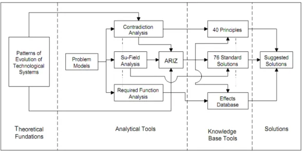
Fig 1.1 BDAS in the engineering design process ... 3 Fig 1.2 Impact of decesions at the early design stage after (Wang, Shen et al. 2002) ... 4 Fig 1.3 The dangerous zones sized at the various levels after (Houssin, Bernard et al. 2006) ... 9 Fig 1.4 Structure of the thesis ... 11 Fig 2.1 The basic engineering design process ... 18 Fig 2.2 Axiomatic domains after (Suh 2001) ... 21 Fig 2.3 Structure of TRIZ theory after (Altshuller and Shulyak 2002) ... 24 Fig 2.4 The design square modeled by C‐K theory after (Hatchuel and Weil 2003) ... 25 Fig 2.5 The engineering design process with four phases after (Pahl and Beitz 1996) ... 27 Fig 2.6 Computer expressions of the product design ... 28 Fig 2.7 Knowledge‐centered view of AI design ... 30 Fig 3.1 Dangerous zones between two rollers ... 46 Fig 3.2 Global view of behavioural design modelling ... 47 Fig 3.3 UML activity diagram of behavioural design approach ... 48 Fig 3.4 The concept of task mode ... 50 Fig 3.5 Task mode ... 51 Fig 3.6 The “Technical Task” Concept ... 52 Fig 3.7 The “Socio‐technical Task” Concept ... 54 Fig 3.8 The relationships between task, structure and structure’s behaviour ... 57 Fig 3.9 The relationships between task, manual function and user’s behaviou ... 58 Fig 3.10 The global view of the Task model ... 60 Fig 3.11 Task Plans ... 62 Fig 3.12 Behavioural analysis process ... 65 Fig 3.13 Knowledge based behavioural design modelling ... 70 Fig 4.1 Framework of distributed BDA system for engineering design ... 82 Fig 4.2 Use case diagram for the designer as the behavioural analyst and the knowledge user 85 Fig 4.3 The entire class diagram of the BDA system ... 87 Fig 4.4 Sequence diagram of Behaviour_Analysis_Package ... 88 Fig 4.5 Activity diagram of consumer login into the BDA system ... 90 Fig 4.6 Statechart diagram of Login_UMI ... 91 Fig 4.7 Corroboration of the dynamic aspect of the BDA system ... 93 Fig 4.9 Encapsulation of structure and behaviour in a composition ... 94 Fig 4.10 Analysis of the structure derived from the Solidworks (structure task) ... 95 Fig 4.11 Classification and analysis of the structure task ... 96 Fig 4.12 Analysis of manual function (user task) ... 97 Fig 4.13 Classify and analysis of user tasks ... 98 Fig 4.14 The evaluation of Task Comparison ... 99 Fig 4.15 Main frame of BDAS ... 100 Fig 4.16 (a) Start cover, (b) Login interface ... 101 Fig 5.1 Typical model of utility cutter ... 104Fig 5.2 Analysis of the utility cutter derived from Solidworks (structure task) ... 105 Fig 5.3 A behavioural comparison for a standard utility cutter ... 106 Fig 5.4 Classification and analysis of user tasks (utility cutter) ... 107 Fig 5.5 The evaluation of Task comparison (utility cutter) ... 108 Fig 5.6 The result of Task Comparison ... 108 Fig 5.7 New style of utility cutter ... 110
List of Tables
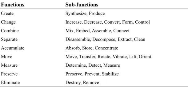
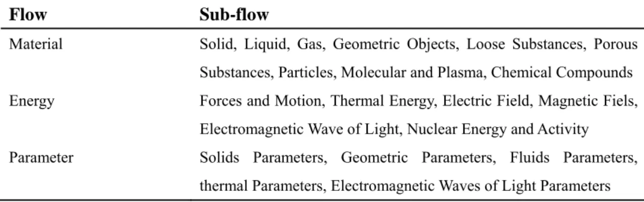
Table 2.1 Characteristics of the 4 domains of the design world after (Suh 2001) ... 22 Table 2.2 Comparison of different computer expression of the product design ... 29 Table 2.3 The FBS design steps ... 33 Table 2.4 Universal attributes of design theories and approaches ... 36 Table 3.1 Abstracted list of functions and sub‐functions ... 41 Table 3.2 Abstracted list of flows and sub‐flows ... 42 Table 4.1 Summary of various software systems ... 78 Table 4.2 The explanations of the icons in BDAS ... 102Chapter 1 Introduction
Along with 1) increased product complexity, 2) the urgency of market equipment, 3) standards requirements, and 4) the spread of the networked product development mode, companies must guarantee a more important estimation of the user activities required to use the system. The designers have to set aside the 100% automated machine because of the vital requirements of the user to perform some definite tasks with machines. In order to improve mechanical system performance, our research targets a better integration of system and user behaviour during the early design phase. In our case, the mechanical system could be a production system, a machine, a product or any tool handled by a user. Use conditions (each model of the mechanical system is designed for and intended to be used in a specific set of conditions) are directly influenced by design results, which also constitute the major factor for improving system performance.
Mechanical engineering design processes are often technology-centered and have difficulties to integrate user’s behaviour in term of using the product adequately. This problem is encountered along the whole life cycle of a project, and is especially noticeable during the early design phase. Although, industry and academia agree that human aspects are important for the success of the product, there are few methods that support the designers concerning these factors in the synthesis part of the design works.
The focus of this research is the development and evaluation of a top-down technical and socio-technical framework for engineering design, which integrates various knowledge bases and the task model. The rationale behind such a framework is to develop a behavioural design approach not in a technology-centered approach, but with a socio-technical approach, in order to help designers to optimize the product performance through taking into account using conditions and requirements during the early design phase. We propose here a design approach that integrates user’s and system’s behavioural data as design specifications. We attempt to provide seamless integration means by merging engineering data and user-centered data within the engineer’s toolkit. Otherwise, classical user-centered approach may seem difficult to handle by the whole design team: in this respect, this work provides a formal integration model in the framework in mechanical engineering design.
This thesis is accomplished at the Laboratoire de Génie de la Conception (LGéCo) and University of Strasbourg and financed by the China Scholarship Council (CSS).
1.1 Objective and position of our work
The objective of this research is to develop a design methodology for mechanical engineering design during the early design phase, which takes care of the structure behaviour and user behaviour, and provides a modelling formalism which can realize the behaviour comparison. As a result, the design quality can be assured, the use conditions can be safety.
We propose an approach to help the designer optimize product performance from the early design phase, taking into account utilization conditions and requirements. This approach is based on a Task Model and the fact that the behavioural system (system and end-user) must be studied and defined from the early design phase. We focus on a production system design, and so, to complete the mechanical system design method, we propose a global view of the behavioural design approach in the early design stage.
Our intention in that regard is to help the designer answer the following questions early in the design process:
z What does the system do to fulfil its automated functions? z What does the user do to fulfil manual functions?
z How does the system fulfil its function according to both the designer’s point of view and the user’s point of view?
z What is the interaction between the user and the system when fulfilling the functions?
z What are the parameters needed to:
z Define the place, the duration, and the nature of the task carried out by the user and the system?
z Have maximum global system performance by minimizing the influence of user ability on global system performance (Buzacott 2002)?
To answer these questions, we propose the behavioural design approach. Where, as noted by Darses (Darses and Wolff 2006), the designer does not have many direct inputs concerning the real needs of end-users, indirect inputs, such as human factors, information provided by ergonomics guidelines, and task analysis, can bridge this gap. However, this does not prevent the designer from referring to his own experience and knowledge of the user’s behaviour. These representations of use, whatever their nature, play a decisive role in the choice of a solution (system structure).
This behavioural design approach relates both to tasks done by the system and the users. For example, to load a machine (function identified by FA) what must the machine do, as a task, to be loaded? What will the user do, as a task, and how will he achieve this task to effectively fulfill this function? What are the consequences of their interaction? For example, must the user stop the machine in order to load it, or is
it possible to load it otherwise? Is this interaction dangerous? Does it require safety measurements? If so, what could these safety measurements be? What are their effects on machine performance? Specifically, the actual integration of aspects regarding safety, accessibility, usability and user ergonomics is carried out too late in the process to meet the requirements and propose some safety procedures to be applied by the user; moreover, these procedures are often hard to apply, and sometimes require that the machine be stopped (Hasan, Bernard et al. 2003; Houssin, Bernard et al. 2006). This late integration leads to reduced system performance. Some investigations have been performed to consider other lifecycle constraints at the early stage of the design process. We intend to optimize the interaction between the system and its potential users from a socio-technical point of view, starting from the early design phase (Carayon 2006). To that end, a global view of the behavioural design approach is proposed as a feasible solution to improve system performance starting from the early design phase.
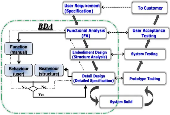
The ultimate goal of this work is to realize a computer aided design tool for mechanical engineering design that can provide higher design efficiency in terms of design lead time and lead designers to better design quality, as shown in figure 1.1.
Fig 1.1 BDAS in the engineering design process
1.2 Background
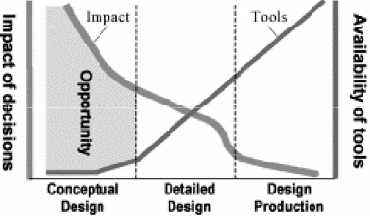
Mechanical engineering design is a process of divergent thinking and routine design. It contains multi-trade approaches which allow taking into account different kinds of criteria. It is the solution of a function used to meet different kinds of techno-economic indicators, and is intended to establish the optimal plan from different possible proposals (Feng and Song 2003). It is widely known that the bulk of the production cost is incurred at the end of the design process (Hsu, Chuang et al. 2000), and as a result it is therefore crucial to avoid errors in the design stage. As shown in figure 1.2, the impact of design decisions is initially very high and declines steeply as the design matures (Wang, Shen et al. 2002). A great opportunity exists at the early design stage to make a few reading decisions.
Fig 1.2 Impact of decesions at the early design stage after (Wang, Shen et al. 2002)
Several relevant concepts are rising from the early design stage. Designers have to perform a first choice among these concepts. In order to limit the duration of the design process and to decrease the risks, they tend to focus very early towards a solution they can handle. So, the alternatives might be eliminated, because they are unknown, unused or non-evaluated. Then, starting from a chosen concept, embodiment design aims to define rough arrangements and structural dimensions of the intended product, in accordance with technical, economic and aesthetic considerations (Pahl and Beitz 1996). Designers have to identify key parameters relevant for this definition. Even if there are few parameters and standard elements for a simple mechanism, there is however a great number of possible combinations. Then, designers make their choices (Hicks and Culley 2002), based on their own experiences and knowledge. So, design iterations cannot be avoided between the early design phase, before reaching design solutions (Ashby, Décarroux et al. 2000; Dieter, Schmidt et al. 2009). Moreover, the embodiment solutions are depending on these initial decisions, which greatly limit the field of design investigations. Another
difficulty in an integrated engineering context is the disagreement, as soon as possible, among the different points of view of the designer, user and technical skills (technical data, marketing data, company identity, environmental data, ergonomics, cultural and symbolic aspects).
In industry, current design approaches, such as Concurrent Engineering (Moustapha 2006), are often focused on the technical satisfaction required by customers. A range of methods for studying users and involving them in the design process have been developed based on User-Centered Design (Redstrom 2006; Redstrom 2008). However, user-centered design is rather difficult and expensive to apply because it takes time to gather data from and about users, especially if the idea is to understand the environment in which they will be using the products. The process requires resources, both financial and human. Another approach is Axiomatic design, which is proposed as a systems design methodology using matrix methods to systematically analyze the transformation of customer needs (Suh 2001) into functional requirements, design parameters and process variables. Finally, user needs (facility, safety, etc.) are often taken into account at the last phase of the design process in a bid to respect legislation and standards.
Many works in the literature confirm the fact that human integration is necessary and crucial in the design process (Obradovich and Woods 1996; Potter, Roth et al. 2000; Hendrick. 2003; EIMaraghy and Urbanic 2004). Marsot (Marsot 2005) holds that imposing the least possible demand on the user (do the job harmlessly, effortlessly, comfortably) now complements the initial aim involving performance-related efficiency (do the job better and quicker than by hand). To fit users’ needs and preferences (i.e., to have a high degree of user fitness), rather than focusing just on the functional factor, designers must also consider psychological, cultural, social and ideological factors (Siu 2003). Wu et al. (Wu, Lo et al. 2006) call for “establishing design processes in which the end-users themselves can influence the design so that it is compatible with their goals and beliefs, etc”. Sundin et al. (Sundin, Christmansson et al. 2004) claim that it is not enough to improve workplaces and production systems themselves; it is also necessary to involve “the earlier step that affects the production system, i.e., the system design”. Sagot et al. (Sagot, Gouin et al. 2003) hold that only a multidisciplinary approach combining social sciences and engineering sciences can respond to the challenge of the human factor being given greater consideration in the design of products. Other works propose to improve existing system performance using information systems. These information systems take into account the user behaviour (Hayman and Elliman 2000), modelling of users’ capabilities and the organization (Juran and Schruben 2004), and using dynamic task allocation (Buzacott
2002). Moreover, users’ expertise often allows considerable autonomy over the design and execution of their work (Lind and Sulek 2000; Pilemalm, Lindell et al. 2007). However, in all these works, the technical system is already designed and is theoretically in use in the designer’s imagination. The utilization aspects are only taken into account in the last step.
Through a case study, Cullen (Cullen 2007) shows that to facilitate the identification and assessment of user requirements, human factors must be integrated into the design from the start of the design lifecycle. However, sometimes it is difficult to integrate user factor into design because of his unknown. In Product Life-cycle Management (PLM), product design is a complex process during which stakeholders in various trades try to take into account all the phases of the product lifecycle (Gardoni 2005). Also, Noël (Frederic Noel 2006) focus on the need to have a multi-view model for sharing the product behaviour throughout the entire product lifecycle, including the utilization phase, where the system is used by the end-user. He distinguishes two behaviour paradigms: derived behaviour, issuing from an analysis activity, and expected behaviour, as a functional requirement for product design. So we propose, in this work, to concern the expected behaviour and derived behaviour during the early design phase.
Over the last two decades, several computer-based design methodologies have been proposed to increase the effectiveness and achieve better control over the design process. Computers have been used extensively in areas such as simulation, analysis and optimization, but relatively few applications exist at the early design stage. This is because knowledge of the requirements and constraints during this early phase of a product’s lifecycle is usually imprecise and incomplete. This lacuna makes it difficult to utilize computer-based systems or prototypes (Hasan, Bernard et al. 2003). There are many software applications and tools which could be used for design, such as CAD, CAM, CAE, CAPP, but which still rely primarily on geometric data (Houssin, Bernard et al. 2006). However, these commercial CAD systems are normally applicable on the product structure and its movement from a technical point of view, as the evaluation of the reliability or the kinematic. This evaluation is only half the track of a whole design process, and some critical issues are still present, such as a shortage of data on the consequences of this movement for the use of the product, like hazards and/or dangerous zones generated by the movement. Houssin and Gardoni (Houssin and Gardoni 2009) propose a Computer Aided Safety Integration in Design process (CASID) approach to help designers integrate users’ safety in the design process. This lack of data is at the root of the loss of performance noted at the user site. In reality, standards require that the system be stopped if the user has to intervene
in a dangerous zone or could be exposed to a hazard in performing his task. CAD technology is not yet at the level of development allowing it to take this type of data into account. To minimise this lack, a software application is in development to support and allow a systematic utilization of the “behavioural design” approach by integrating it into the daily work of the designer.
Process modelling describes design work, which is usually supported by some known methods. Design process modelling is implemented mainly through the mapping of function and structure. Most processes modelled are extended from two basic frameworks: Function-Structure (FS) (Pahl and Beitz 1996; Suh 2001) and Function-Behaviour-Structure (FBS) (Gero 1990; Umeda and Tomiyama 1997; Labrousse 2004). The FBS framework was first advanced by Gero (1990), who pointed out that the structure expresses the internal and external states of a physical element. This type of framework considers that function and structure must be linked through behaviour 1) to depict the action that is executed to complete a function, and 2) to indicate “how structure fulfils the function”. Nowadays, early system design is regarded as an ordinal process of mapping of function, behaviour and structure. Stalker (Stalker 2002) improved the FBS framework to take into consideration the elaboration of product models in terms of Function, Behaviour and Structure. In this framework, the author illustrates that when a product exists physically; its situation and use conditions are easily identifiable and may be affected by its function. This framework presents steps (Function, Behaviour and Structure), with the designer going from one step to another in completing processes (formulation, synthesis, analysis, comparison, construction, etc.). In this framework, the author states that in the design phase, there are two behaviours (expected and predicated), which must be considered. Stalker extended this framework, proposing the undated behaviour, which results from feedback using a product prototype (the physical use situation). It is often used in knowledge management, and has been enriched by Labrousse (Labrousse 2004), who proposed the integration of Process, Product and Resource (FBS-PPR). Unfortunately, this framework only covers product behaviour, while ignoring end-user behaviour; moreover, it does not go so far to propose how these behaviours could be characterised and what their influence on product performance might be. Hasan et al. (Hasan, Bernard et al. 2003) and Houssin et al. (Houssin, Bernard et al. 2006) proposed a “Working situation” model, in which they modelled the task of the end-user and of the product in identifying the risks that could be generated when the end-user performs his task in an identified dangerous zone. However, this model does not go as far as analysing the nature of different tasks or their types. As well, it does not identify their influence on product performance. The authors proposed this model
simply to aid the designer in integrating end-user safety in the design process. Our work, detailed in the following chapters, adapts from this Function, Behaviour and Structure approach.
It must be stated that all these important contributions do not yet offer any formalized methods or tools to help a designer study and evaluate behaviour and to carry out a Behavioural Analysis complementary to a Functional Analysis during the design stage.
1.3 Problem statement
Mechanical engineering design is connected with human behaviours targeted at and eventually leading to the development of the product. These behaviours take place all over the product lifecycle. In order to improve product performance, our research carefully thinks out a piece of research linking the user cantered and functional engineering design approached into an integrated package. It aims to a better integration of product and user behaviour during the early design phase. Designers have been obliged to set aside their dreams of a 100% machine due to the vital requirement of the user to perform some definite tasks with machines. While machine productivity and use conditions are the main reasons for automating production systems, human intervention on such systems remains a critical need and the tasks performed by the user remain poorly defined at the early design stage.
In traditional engineering design, designers normally take into consideration product functions and structures, while users’ behaviours in terms of using the system are generally not fully considered during the early design phase. A product’s behaviour is studied only from a technical point of view in order to verify its reliability and potential problems in the detailed design phase. However, this behaviour is neither characterised nor studied from a use point of view. Nowadays, although designers do increasingly have some understanding of user behaviour, they rarely pay much attention to the behaviour which derives from the structure (how the structure will move to fulfil the function), and behaviour which is fulfilled by the user (how the user will react to the machine).
Here, we quote two examples observed in real companies in order to reveal some factors of user behaviour in terms of using the system.
z Example one: Amusement equipment such as rotary amusement and rail amusement equipment, among others, are generally operated by workers. Moreover, passengers are in a position of being controlled; it is thus hard for them to choose and control the motion, and their fate is totally tied to the machine. Users here refer to two groups of persons: workers (operators) and passengers
z Fig Clas prob (clients). R from incor (Bagge an distance th danger. Du regulations behaviour. reduce inju movement Example t designers dangerous of the dang person is e our resear Figure 1.3 g 1.3 The da z Techn pheno z System techni may b z Worki system install create betwee ssically, the blem, desig Regarding rrectly trans nd Pendrill 2 he human fr ue to the da s be adopt Personal p ury. Howev t, visibility a two: At a P try to red phenomeno gerous zone exposed to ch, the dan . angerous zon ical solutio menon. m level: in cal solution e modified ing situation m installatio ation of a a dangerou en the mobi e utilization gner shoul equipment sferring and 2002). Vari rom the mac
anger posed ed and set protection e ver, such p and accessib Printer Man duce the da on is bound e defines an a risk of h ngerous zon es sized at th on level: n which w ns. In this le or even dis n level: in on but resu mobile org us zone bec ile organ an n of the prod ld add som operators, d converting ious safety chine in ord d by the de t up, and m equipment personal pro bility, but al nufacturer’s angerous ph ded accordin ny zone insi hurt or healt ne can be s he various lev in which we represen evel, the dan
appear. which a d ults from it gan near a cause of ris nd the wall) duct is stud me new fu the main m g from kinet protection der to keep t esign, it is managemen should also otections co lso require t s, in order henomenon ng to its nat ide and/or a th damage situated at vels after (H could be nt the dime ngerous zon dangerous z ts integratio wall or ne sk of crush . died in proto functions, s mechanical tic to the po devices can the operator crucial that nt should s o be provid ould not on time to be p to respect n. Usually ture in a zon around a sys (Standardiz three level Houssin, Bern engendered ension ‘ass nes defined i zone does n on on using ear another h between b otyping pha such as so l danger co otential en n be adopte r far away f t various sa tipulate hu ded to avoi nly restrict put on. the legislat the potent ne. The con stem in whi zation 1994 ls, as show nard et al. 20 d a dange sembly’ of in the first l not exist be g site (e.g. r system w both system ase. If there ome protec omes nergy ed to from afety uman d or user tion, tially ncept ich a ). In wn in 06) erous f the level efore . the would ms or e is a ction
equipments which make product safe in use. If it is not possible, designer propose some coercive utilization procedures. These equipments and procedures could decrease product reliability and availability and by consequence its performance. In this stage, designer’s choices are limited by the product itself and all modifications could be very expensive.
Additionally, early product development phases are considered to have the most influence on major changes of products in general. Thus the changing of products and product systems towards a sustainable development has its highest potential in early design phases. Furthermore, product development is becoming increasingly complex within industry. Taking into consideration the impact of utilization conditions of a new product is one more task to be added and integrated into the long list of things already under consideration.
Due to the complexity of the situation, there is a real need for efficient and easy-to-understand design methods applicable to product development and design. Adapting products to achieve a sustainable society, together with customer preferences and the complex situation facing designers constitutes the basis of this thesis. Moreover, this work develops a methodical approach for assisting designers in their endeavors to improve the product performance during the early design phase through taking into account using conditions and requirements, while taking into account other functional requirements at the same time.
1.4 Structure of the thesis
In the above sections, we explain the general introduction about our research, which includes the background, problem statement, as well as the research questions and aims.
The rest of the thesis is organized as follows:
Chapter 2 reviews the related work in order to shed light on the characterization and representation of design, engineering design and study of design theories and approaches. Three streams of related works are reviewed: a. the definitions of design; b. state of the art of the characterization and representation of the engineering design and engineering design process; and c. design theories and approaches from different kind of perceptive and criteria.
Chapter 3 proposes a global view of the behavioural design approach integrated with the task model and knowledge bases as a feasible solution to improve system performance starting from the early design phase. Two domains are explored, namely task domain and knowledge domain. A generic task model and knowledge based behavioural design model are developed respectively. A UML based representation
sche beh Cha part Beh othe soft the The eme is also avioural de apter 4 dev ts are inclu havioural De er part is th tware applic “behaviour e whole stru developed sign approa elops a Beh uded in this esign Appro he impleme cation is in d al design” a ucture of the according ach. havioural D s chapter. O oach (BDA entation of t developmen approach by e thesis is ill Fig 1.4 S to the char Design App One part co A) system fo the system nt to suppor y integrating lustrated in Structure of t racterization proach Softw oncerns fram or mechanic in C++ pro rt and allow g it into the figure 1.4. the thesis n and repres ware (BDA mework of cal engineer ogram langu w a systemat daily work sentation of AS). Two m f the distrib ring design. uage. Final tic utilizatio k of the desi f the major buted The lly, a on of igner.
Chapter 2 The state of the art
The previous chapter introduced the core research question of the thesis and the general motivation behind it. Here in the second chapter, we study the state of the art from multi-disciplines by adopting a divergent-convergent review strategy.
The product design process is the primary phase and also the creative part during the product life cycle. The implementation effect of the follow-up manufacture process is directly influenced by design results. The design results are also the major factor of controlling the product cost and use. Product design theories and methods have attracted widespread attention by academic and industrial research. And the design theories and methods have become important research areas and application fields. The reasons are as follows: 1) the increase of product complexity; 2) the urgency of market equipment; 3) the spread of the networked product development mode.
Design is one of the most crucial sectors of the economy. In recent years, more and more countries are realizing that design brings wealth to their societies. Design has been considered as both a technical and a socio-technical activity.
Here, we concentrate our study on the state of the art of design in the aspects of design theory, design process and knowledge.
2.1 Definitions of design
Design is a complex, multifaceted and broad concept with no universally agreed definition. There is agreement that design as a noun refers to a plan for the construction of an object while “to design” (verb) refers to making the plan. Here, we constrain our research into the engineering design field. So the main task of design is the application of their scientific and engineering knowledge to find and optimize solutions within the diverse requirements (Pahl and Beitz 1996).
Different aims of design bring on different design activities and definitions. Many researches and institutions define design from several standpoints. The UK Department of Trade and Industry (Department of Trade and Industry 2005) said the following about design: “Design is a structured creative process. Design is readily
associated with industrial product design for manufactured products -specifically the ‘look’ of a product. However, the application of design is much broader, for example designing for function; for aesthetic appeal; for ease of manufacture; for sustainability; and designing for reliability or quality and business processes themselves.” Design is a creative activity whose aim is to establish the multi-faceted
Therefore, design is the central factor of innovative humanization of technologies and the crucial factor of cultural and economic exchange (ICSID 2008). In nature, in design revolution today design is a tool for innovation and development.
Design is a process, an activity, and not only the results of that activity. Simon (Simon 1969) proposed that “everyone designs who devise courses of action aimed at
changing existing situations into preferred ones”. Design is an inseparable part of the
overall technological system and provides the primary source database for all other activities in the system (Yoshikawa 1989). Design activity can be characterized as a goal-oriented, constrained, decision-making, exploration and learning activity which operates within a context which depends on the designer's perception of the context (Gero 1990). Hinrichs (Hinrichs 1992) defines design as “the task of generating
descriptions of artifacts or processes in some domain”. The definition provided in
Engers et al (van Engers, Gerrits et al. 2001): “design is the creative process of
coming up with a well-structured model that optimizes technological constraints, given a specification”.
The government of New Zealand (NZIER 2003) defines design as follows: “Design is
an integrated process. It is a methodology (or a way of thinking) which guides the synthesis of creativity, technology, scientific and commercial disciplines to produce unique (and superior) products, services, and communications”. Some governments
prefer talking about the potential of good design. The Danish government’s 2007 white paper (Danish 2007) defines the good design as the following:“Good design is
an increasingly important means for businesses to hold their own in international competition. Design has the power to make products and services more attractive to customers and users, so they are able to sell at a higher price by being differentiated from the competition by virtue of new properties, values and characteristics”.
As highlighted by several of the definitions above, design is an activity that follows a certain methodology and a number of steps — such as research, conceptualizing, modelling, testing and re-design — and not only the results of that activity.
As Dieter et al. (Dieter, Schmidt et al. 2009) said in his book, the way to summarize the challenges presented by the design is to think of the four C’s of design:
z Creativity: requires creation of something that not existed before or not existed in the designer’s mind before;
z Complexity: requires decision on many variables and parameters;
z Choice: requires making choices among many possible solutions at all levels, from basic concepts to smallest detail of shape;
z Compromise: requires balancing multiple and sometimes conflicting requirements.
Design allows a broad range of considerations to be taken into account. Design as a purposeful and goal-oriented activity takes on various forms in practice. It is a holistic approach which allows a range of considerations beyond aesthetics to be taken into account, including functionality, ergonomics, usability, accessibility, product safety, sustainability, cost and intangibles such as brand and culture (European Communities 2009). The aim of design could be competitiveness and differentiation on international markets, or it could be sustainability and quality of life.
In short, design as an activity can and often does take place in any organisation (Community Design Regulation 2002). Design as a driver of user-centred innovation is a structured innovative process
2.2 Engineering design
Since design is detached from manufacturing because of the labour division and the specialization, two streams of design have been developed separately: design as art and design as engineering (Von Stamm 2003). The engineering design can be applied to several endings. One is the design of products, whether they are consumer goods and appliances or highly complex products. Another is a complex engineered system such as the production systems. The emphasis in this thesis is on complex product design because it is the area in which many engineers will apply design skills.
Since design stands at the core of both the craft and engineering traditions, its meaning and usage in technique is not always settled. Where craft design draws on aesthetics primarily, engineering design has both creative as well as rational dimensions (Cross and Knovel 2000).
In engineering design, the end goal is the creation of an artifact, product, system, or process performs a function or functions to fulfill customer needs. Conceptualizing, defining, or understanding an artifact, product, or system, in terms of function, is a fundamental aspect of engineering design (Hubka and Eder 1982; Ulrich and Eppinger 1995; Pahl and Beitz 1996; Ullman 1997; Otto and Wood 2001).
Dieter (Dieter, Schmidt et al. 2009) has written further that engineers work “at the
margin of solvable problems,” proceeding from the known to the unknown. They
work under conditions of change, uncertainty, and resource constraints. Dieter explains that unlike scientists who proceed within the framework of scientific laws, engineers employ heuristic laws to arrive at design solutions.
Pahl and Beitz (Pahl and Beitz 1996) write that the main task of engineers is to “apply
their scientific and engineering knowledge to the solution of technical problems, and then optimize those solutions within the requirements and constraints set by the material, technological, economic, legal, environmental and human-related
considerations”.
Beyond the technical, engineering design can also be situated in the domain of the philosophy. It is creative, requiring grounding in mathematics and science, as well as in domain specific knowledge and experience (Lewis 2005). These authors identify types of design, goals and methods.
Types include:
z innovative: new tasks and problems needing original design, which must proceed through all phases (Gero and Kannengiesser 2007);
z adaptive: established solution principles held continuous but the realization is adapted to alterative requirements;
z variational: sizes and arrangements of parts are varied within the original design parameters.
Goals include:
z optimization of function; z minimization of cost; z aesthetic considerations;
z ergonomic considerations (Das and Sengupta 1996). Solution methods include:
z traditional (e.g. literature review);
z intuitive, inclusive of preconscious or subconscious ideas or insight or flash, brainstorming, or using analogy;
z discursive, use of design catalogs or systematic combinations.
Among these various explanations of engineering design, there are two different exemplifications, which are the problem solving (Simon 1969) and the reflective practice (Schön 1987). Problem solving is a mental process and is part of the larger problem process that includes problem finding and problem shaping. Considered the most complex of all intellectual functions, problem solving has been defined as a higher-order cognitive process that requires the modulation and control of more routine or fundamental skills (Simon 1969). Problem solving paradigm is set up on the epistemology of positivism, while the reflective practice paradigm is built on the epistemology of constructivism (Pahl and Beitz 1996). Reflective Practice is the capacity to reflect on the action so as to engage in a process of continuous learning, which, according to the originator of the term, is one of the defining characteristics of professional practice (Schön 1987).
2.3 Engineering design process
engineer in creating a product. The engineering design process is defined as: “the
process of devising a system, component, or process to meet desired needs. It is a decision making process (often iterative) in which the basic sciences, mathematics, and engineering sciences are applied to convert resources optimally to meet a stated objective. Among the fundamental elements of the design process are the establishment of objectives and criteria, synthesis, analysis, construction, testing and evaluation” (Ertas and Jones).
It means that the engineering design process is the set of activities by which designers develop and/or select the means to achieve a set of objectives. The engineering design process may bring about the creation of a new solution, the selection of an existing solution, or a combination of the two.
2. 3.1 The importance of the engineering design process
Here, we introduce two quotes to emphasize the importance of design in the product realization process:
z “Studies have shown that 50 to 80 percent of the life cycle cost of products
are influenced in engineering design” (PREVIEW 1995).
z “After all, 70% of a product’s total cost is determined by its design, and that
cost includes materials, facilities, tooling, labour, and other support costs”
(Munroe 1995).
The two quotes not only indicate the large impact that the engineering design process has on product cost but also some of the other considerations that go into the product realization process, such as tooling, facilities, and labour. These other considerations dictate that certain members of the engineering design team must be knowledgeable in these other areas.
2.3.2 Detailed description of the engineering design process
Morris Asimow (Asimow 1962) is among the first to give a detailed description of the complete engineering design process in what he called the morphology of design. Pahl and Beitz (Pahl and Beitz 1996) provide one of the better known engineering design process. One of the useful parts of this process is the fact that it not only shows the steps, it shows what the output of each step should be. The list of the engineering design process described below is established by researching the literatures (Ertas and Jones ; Hubka and Eder 1982; Pugh 1991; Pahl and Beitz 1996; Cross 2000; Dieter, Schmidt et al. 2009).
2.3.2.1 Phase I: Conceptual design
by which the design is initiated, carried to the point of creating a number of possible solutions, and narrowed down to a single best concept (Dieter, Schmidt et al. 2009). The objective of this phase is to determine the principal solution. Some of the terms used by Pahl and Beitz to describe it are:
1. Identification of customer needs: The objective of this activity is to completely understand the customer’s need and to communicate them to the design team. (but in our paper the customer needs and user needs are not the same things)
2. Problem definition: The objective of this activity is to make a statement that describes what must to be accomplished to satisfy the customer needs. Quality function deployment (DFD) (Akao 1990) is a valuable tool for linking customer needs with design requirements.
3. Gathering information: The objective of this activity is to ensure that you benefit from the work of others (i.e. don’t reinvent the wheel!).
4. Concept generation: Concept generation is involved with creating a broad set of concepts that potentially satisfy the problem statement.
5. Concept evaluation: Evaluation of design concepts, modifying and evolving into a single concept.
2.3.2.2 Phase II: Embodiment design (Preliminary design)
In this phase a structured development of the design concept takes place. Embodiment design consists of preliminary layouts and configurations, selecting the most desirable preliminary layouts, refining and evaluating against technical and economic criterion (Cross 2008). Embodiment design is concerned with three major tasks:
1. Product architecture: It is concerned with dividing the overall design system into subsystems.
2. Configuration design: It means to determine what feature will be present and how these features are to be arranged in space relative to each other.
3. Parametric design: It starts with information on the configuration of the part and aims to establish its exact dimensions and tolerance.
2.3.2.3 PhaseIII: Detail design
In this phase the design is brought to the stage of a complete engineering description of a producible product. The detail design includes specifying the materials, the sizes, the type of motor, the size of the hydraulic pump and cylinders, where the attachment and assembly holes should be drilled, the size of the holes, etc. It requires a lot of skills to specify this myriad of items correctly if the design to “go together” in a satisfactory manner (Hubka and Eder 1982). Many alternatives and options should be
considered during this phase of the engineering design phase.
2.3.2.3 PhaseIV: Iterations
All of the steps or phases of the engineering design processes indicate feed-back arrows which indicate re-doing or iterating the steps. It is important to note the iterative nature of the engineering design process. Various stages may be visited multiple times during the evolution of your design.
This re-doing is necessary because we seldom know enough at any stage of the design process to produce a complete answer, let alone the best one. For instance, we must define the problem to begin, but the beginning is precisely when we know the least about the system that we are designing. We learn about its characteristics, performance and limitations as we design.
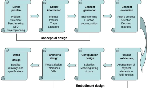
The basic engineering design processes described above are displayed in figure 2.1.
Fig 2.1 The basic engineering design process
This eight-step process is the representation of the basic engineering design process. The purpose of this graphic is to illustrate the logical sequence of activities that leads from the problem definition to the detail design. It constitutes the primary design process. However, the design does not normally proceed in a straight-line fashion. Much iteration will be necessary and can be expected for the final process.
Phases I, II and III take the design from the realm of possibility to the real word of practically. However, the design process is not finished with the delivery of a set of detailed engineering drawings and specifications. Many other technical and business
Define problem Problem statement Benchmaking QFD Project planning Define problem Problem statement Benchmaking QFD Project planning Define problem Problem statement Benchmaking QFD Project planning Gather information Internet Patents Trade Literature Concept generation Brainstorming Function decomposition Concept evaluation Pugh’s concept selection Decision matrices Define problem Problem statement Benchmaking QFD Project planning Define problem Problem statement Benchmaking QFD Project planning Detail design Detailed drawings and specifications Parametric design Robust design Tolerances DFM Configuration design Selection Modeling/sizing of parts product architecture, Arrangement of physical elements to fulfill function Conceptual design Embodiment design Define problem Problem statement Benchmaking QFD Project planning Define problem Problem statement Benchmaking QFD Project planning Define problem Problem statement Benchmaking QFD Project planning Gather information Internet Patents Trade Literature Concept generation Brainstorming Function decomposition Concept evaluation Pugh’s concept selection Decision matrices Define problem Problem statement Benchmaking QFD Project planning Define problem Problem statement Benchmaking QFD Project planning Detail design Detailed drawings and specifications Parametric design Robust design Tolerances DFM Configuration design Selection Modeling/sizing of parts product architecture, Arrangement of physical elements to fulfill function Conceptual design Embodiment design
decisions must be made that are really part of the design process.
In order to understand the realization of the engineering design process, we will review some known design theories and approaches in the following section.
2.4 Design theories and approaches
Over the last decades, most engineering design researchers have focused on developing prescriptive design methods such as the Systematic Approach (Pahl and Beitz 1996). Descriptive design theory was underestimate and sometimes ignored (Reich 1995). Few industrial design practices have a scientific or theory background. Engineering design is mainly performed on the basis of the designer’s experiences. On the other hand, no existing design theories have been really used in the industry because they mainly deal with the idealized design situations (the gap between theory and its uses). Nevertheless, it is generally agreed that the development of a theory of design will contribute to a better understanding of the design process and a better organization of design knowledge, and consequently allow better performing the design.
2.4.1 Design theories
A theory is an analytical tool for understanding, explaining, and making predictions about a given subject matter (Ayala 2008). Scientific theory is a deductive theory, in that, its content is based on some formal system of logic and that some of its elementary theorems are taken as axioms. In a deductive theory, any sentence which is a logical consequence of one or more of the axioms is also a sentence of that theory (Curry 1977).
A theory of design is scientific if it is developed using a scientific method. A scientific theory of design seeks to explain the design process and predict design results by repeatable or verifiable means. The method upon which the approach is developed is the experimental method consisted of three steps (Wiley 2000):
z The researcher observes facts (designs);
z He formulates hypothesis which can bring an explication to observed facts; z He verifies by experimentation the pertinence of these hypotheses.
A theory of design is generic (or general) if its concepts and principles apply to various design areas. It is generally believed that there are no real differences between the design process that it is engineering products, architecture or civil engineering, chemical ,microelectronics and micro-mechanical products, etc. (Grabowski, Rude et al. 1998). Brown et al. (Brown, Waldron et al. 1998) indicate that although design problems in different domains require different domain knowledge such as knowledge
of equations, components, and the analysis techniques. There are underlying similarities in the form of that knowledge and in the way that is used.
The theory of design explains the phenomena of design by means of a set of concepts and operations between the concepts. It is generally believed that a theory of design is really useful if it is not only descriptive (to explain what is design), but also prescriptive (to show how to better perform design) and/or predictive (to forecast properties of designed objects) (Finger and Dixon 1989; Blessing, Chakrabarti et al. 1998). No theory can capture all of design perspectives; each theory provides one perspective, contributing to improve the understanding of design. Furthermore, developing a theory of design is itself a long and iterative process. The approach presented below is only an intermediate result of that process. To avoid to “reinvent the wheel”, it must be based on the existing theoretical approaches (at least at its early stage of development).
Simon (Simon 1969) is the first to consider the design theory as a science of artificial. Early approaches view the design theory as a generalized problem-solving method (Asimow 1962; Simon 1969; Rittel and Webber 1984). Since the beginning of 1980’s, the research on design theory has gained attention. The first general design theory was proposed by Yoshikawa (Yoshikawa 1989). Various known design theories developed today will be introduced in the following section.
2.4.1.1 General Design Theory (GDT)
General Design Theory (GDT) developed by Yoshikawa (Yoshikawa 1989), based on the philosophical and mathematical considerations, is the most general one. It uses set theory and topology to model design knowledge and design process. Although, it is limited to the study of idealized design process with perfect knowledge structure (topology). And it contributes to a better understanding of the process of designing and the structure of design knowledge from cognitive point of view.
In this theory, Yoshikawa picked up the notions of entity, entity concept, abstract concept, and attribute as basic items for an axiomatic theory of design, and proclaimed three axioms for them called the Axiom of Recognition, the Axiom of Correspondence, and the Axiom of Operation.
The axioms of GDT are basic conditions about the relationship and properties about entities, entity concepts, and abstract concepts.
1. Axiom 1 (Axiom of Recognition) Any entity can be recognized or described by the attributes.
2. Axiom 2 (Axiom of Correspondence) The entity set S’ and the set of concepts of entity (ideal) S have the one-to-one correspondence.
the set of entity concepts.
2.4.1.2 Axiomatic Design Theory (ADT)
Axiomatic Design Theory (ADT) is a systems design methodology using matrix methods to systematically analyze the transformation of customer needs into functional requirements, design parameters, and process variables (Suh 1990). It aims at identifying generalizable principles which govern good design solutions. These principles are formalized in terms of axioms and theorems. The primary goal of axiomatic design is to establish a systematic foundation for design activity by two fundamental axioms and a set of implementation methods. The two axioms are:
z Axiom 1: The Independence Axiom: Maintain the independence of functional requirements.
z Axiom 2: The Information Axiom: Minimize the information content in design.
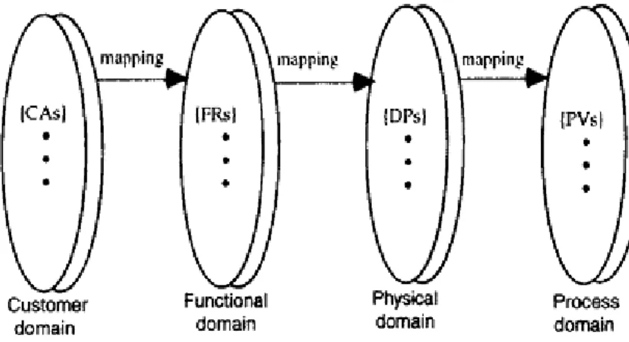
The design process is defined as the set of activities by which designers develop and/or select of a means (design parameters: DPs) to satisfy objectives (functional requirements: FRs), subject to constrains (Csikszentmihalyi). Axiomatic design breaks the design process into four domains, shown in Figure 2.2.
Fig 2.2 Axiomatic domains after (Suh 2001)
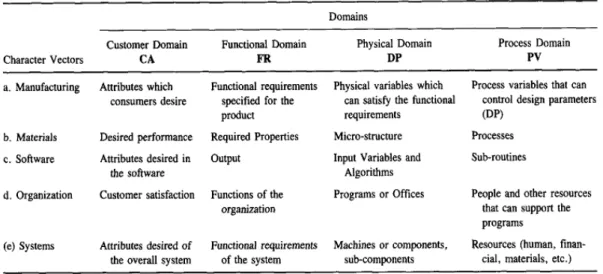
The customer domain can be thought of as the voice of the customer (VOC). The functional domain is initially populated by mapping the VOC into independent measurable functions. High-level functions are driven by the customer; lower-level functions are driven by design choices. Every function must be measurable. The physical domain is the domain of physics, chemistry, math and algorithms. The process domain is where the specifics of how the design parameters identified in the physical domain will be implemented.
consistent for all types of design problems and at all levels of detail. Thus, different designers, as well as observers to the design process, can quickly understand the relationships between the desired functions of an object and the means by which the functions are achieved.
In summary, the main concepts of Axiomatic design are:
1. domains, which separate the functional and physical parts of the design;
2. hierarchies, which categorize the progress of a design in the functional and physical domains form a systemic level to more detailed levels;
3. zigzagging, which indicates that decisions made at one level of the hierarchy affect the problem statement at lower levels;
4. design axioms, which dictate that the independence of the functional requirements must be maintained and that the information content must be minimized as criteria for high-quality design.
In manufacturing, many disciplines and fields are involved, such as mechanical, electrical, hardware and software. However, all designs can be represented using the 4 design domains, enabling us to generalize the design process. The design objectives can be different from one problem to another, but all designers go through the same thought process. Table 2.1 shows how all these seemingly different design tasks can be described in terms of the 4 design domains.
Table 2.1 Characteristics of the 4 domains of the design world after (Suh 2001)
2.4.1.3 Universal Design Theory (UDT)
Universal Design Theory (UDT) is drafted as an on-going research project by Grabowski (Grabowski, Rude et al. 1998). It is based on the systematic design approach and views design process as a finite number of abstraction levels and a set of structured stages to follow. It serves as a scientific basis for rationalizing