HES-SO Valais-Wallis • rue de la Plaine 2 • 3960 Sierre +41 27 606 89 11 • [email protected] • www.hevs.ch
Bachelor Thesis 2016
Virtual Desktop Sizing
Source: http://bit.ly/29WTkyW
Student : Aleksandr Mikheev Professor : David Wannier
Department : Business Information Technology Submitted on : 22th July 2016
i ABSTRACT
This paper is intended to describe a process of choosing and building a demo of virtualization solution for a group of people in campus of EPFL located in a city of Sion, Valais Wallis. The aim of the paper is to compare different desktop virtualization solutions and choose the best one within the given customer’s requirements and infrastructure. The second goal of the paper is to provide a demo implementation of the selected virtualization solution with guidelines describing how it was created and notes on specific customizations required within the given internal computer structure of the campus.
The document presents some theory behind desktop virtualization specifically and the problem customer has with the current solution (chapter 1), comparison of different systems and description of the selected system (chapter 2 and 3) and how the demo solution was implemented within given requirements (chapters 4-6).
Most of the work is based on official specifications and documentation for desktop virtualization system. Since this thesis is a project made for a customer, the main deliverables of it are demo implementation and instructions on how it was created (Appendix I).
ii FOREWORD AND ACKNOWLEDGEMENTS
Virtualization in computer science is a large topic. There are multiple types of virtualization and they perform differently, sometimes completely, if compared on how they work. As an author of the paper, my main intention in selecting this topic was that desktop virtualization nowadays includes most of those types of virtualization combined together within a single platform. Usually the structure of desktop virtualization starts from a generic virtualization platform, which creates an abstraction for running different types of virtual machines, and goes to the actual virtualization of a full user’s computer, which, if examined, hardly differs from a computer running on a real hardware. Since desktop virtualization evolved, it started to gain more features. For example, now it also gives abilities to virtualize not only a complete computer but even a single application, which gives broad possibilities for computer systems of the future.
Another reason in choosing the topic was that I see changes in how computer systems work over time and it seems to me that desktop virtualization is the next trend there. For the last few years all intensive computations were moved to a “client-server” model, where end-user’s computer doesn’t actually perform tasks but only provides an interface for displaying and interacting with data while doing computations on a separate server. Desktop virtualization brings this idea even further: instead of user interacting with a client user interface inside an operating system, which runs on a real hardware, user starts his work by running a client user interface for the operating system itself. As an author of the project, I found it very useful to gain experience in implementing such a solution because it seems logical to me that this idea will eventually replace usual work stations.
This topic was done as a working project accompanied with the thesis paper. During project development the most problematic were technical difficulties because such systems are still new and for some topics there is not enough information. These problems were eliminated by testing different possible implementations and finding those that work the way it was defined by requirements.
I would like to thank Voiselle Joël Gilbert André Robert Emmanuel for providing me with the opportunity to do this research inside EPFL’s campus in Sion and helping in all matters, which required customer’s involvement. Also, I would like to thank my thesis coordinator, David Wannier, who helped me with choosing the right thesis topic and provided help on the first premises.
iii TABLE OF CONTENTS ABSTRACT ... I FOREWORD AND ACKNOWLEDGEMENTS ... II TABLE OF CONTENTS ... III LIST OF TABLES ... V 1. INTRODUCTION ... 1 1.1. VIRTUALIZATION AND DESKTOP VIRTUALIZATION ... 1 1.2. CUSTOMER AND EXISTING CUSTOMER’S SOLUTION ... 4 1.3. PROBLEM TO BE ADDRESSED DURING THE PROJECT ... 6 1.4. PROJECT DEVELOPMENT ... 6 2. CHOICE OF A SYSTEM ... 8 2.1. GROUPS OF VIRTUALIZATION SYSTEMS ... 8 2.2. COMPARISON CRITERIA OF PRODUCTS EXPLAINED ... 9 2.3. SYSTEMS COMPARISON AND COMPARISON CONCLUSIONS ... 11 3. SYSTEM ARCHITECTURE ... 13 3.1. SYSTEM COMPONENTS ... 14 3.1.1.
Active Directory ... 15
3.1.2.
ESX Host ... 15
3.1.3.
vCenter Server ... 15
3.1.4.
View Connection Server ... 16
3.1.5.
Client workstation ... 17
3.2. DIFFERENT APPROACHES TO IMPLEMENTING SYSTEM ARCHITECTURE ... 17 3.2.1.
First architecture ... 18
3.2.2.
Second architecture ... 20
4. SYSTEM IMPLEMENTATION ... 22 4.1.1.
Preparing the hardware ... 22
4.1.2.
Setting up ESXi. ... 22
4.2. SETTING UP ESXI USING VSPHERE CLIENT ... 24
4.3. SETTING UP VCENTER SERVER ... 24
4.4. SETTING UP HORIZON VIEW CONNECTION SERVER ... 25
iv 5. PROJECT MANAGEMENT ... 28 5.1. PROJECT ORGANIZATION (METHODOLOGY) ... 28 5.2. COMMUNICATION WITH THE CUSTOMER ... 28 5.3. MAINTAINING TASKS ... 28 5.4. WORK ORGANIZATION ... 29 5.5. DISCUSSION ON THE RESULTS BETWEEN ITERATIONS OF TASKS ... 29 5.6. RELEASE ROADMAP ... 30 6. PROJECT REALIZATION ... 31 6.1.1.
First month ... 31
6.1.2.
Second month ... 32
6.1.3.
Third month ... 34
7. CONCLUSIONS ... 35 7.1. WORK CONCLUSION ... 35 7.2. POSSIBLE IMPROVEMENTS ... 35 7.3. PERSONAL CONCLUSION ... 36 REFERENCES ... 37 APPENDIX I: SETTING UP VIRTUAL DESKTOP INFRASTRUCTURE WITH VMWARE HORIZON ... 39 APPENDIX II: HORIZON DESKTOP VIRTUAL MACHINES TESTING INSTRUCTIONS ... 62 AUTHOR’S DECLARATION ... 69
v LIST OF TABLES
Table 1. Groups of desktop virtualization providers ... 8
Table 2. Desktop virtualization platforms comparison ... 11
vi LIST OF FIGURES
Figure 1. Virtualization defined visually ... 1
Figure 2. Desktop virtualization ... 2
Figure 3. Some of the characteristics of desktop virtualization solutions ... 3
Figure 4. Components within Horizon 7 infrastructure ... 14
Figure 5. Selected "recommended topology" from VMWare for the vCenter Server ... 16
Figure 6. First system architecture design ... 18
Figure 7. vSphere Web Client - Remote Console feature ... 19
Figure 8. First system architecture design ... 20
Figure 9. ESXi vSphere Host Client administrative panel ... 23
Figure 10. vSphere Client main window ... 24
Figure 11. vCenter Server with ESXi host added ... 25
Figure 12. Horizon View Connection Server with desktop pool installed ... 26
Figure 13. Burndown chart ... 30
vii LIST OF ABBREVIATIONS
Cloud platform (cloud provider) - company that offers remote servers hosted within the company's infrastructure.
DHCP server - a server that automatically provides client computers with IP addresses. Emulation - process of enabling one computer to look and behave like it is another computer. Fully qualified domain name (FQDN) - complete domain name for a specific computer within some network.
HyperThreading - technology by Intel, which makes all processor cores to be doubled, with some restrictions on how this “doubled” cores work.
Internal network (intranet) - network belonging to an organization that is accessible only by organization's members.
IP address - a semi-unique numerical identification label of a computer.
SSL - security technology for encrypted communication between receiver and sender. Virtual desktop - a client computer that is emulated with a virtualization solution.
1
1. INTRODUCTION
Although terms like “virtualization” and “virtual desktop” are commonly used throughout all Computer Science and Information Technologies, finding complete, yet understandable, definitions for them can be hard to achieve. The main reason for that is based on complexity of the term “virtualization” because it is not a new term and it grew throughout the time, initially appearing in 1960s. Nowadays the term includes many areas and, depending on the subject area and implementations, it can have very broad meanings. According to Graziano (2011, p. 3-4), the most drastically changes in virtualization occurred throughout 2000’s, “[when] x86 based systems became more powerful”. For this paper, different definitions of virtualization and virtual desktops were reviewed, selected and their key characteristics were combined together to form an overall picture specific for the subject area and required project’s goals.
1.1. Virtualization and desktop virtualization
Amit Singh (2004) provides, as he says, a “loose definition” for virtualization as a term. This is one of the most understandable and complete definition that can be found at the time of writing: “Virtualization is a framework or methodology of dividing the resources of a computer into multiple execution environments, by applying one or more concepts or technologies such as hardware and software partitioning, time-sharing, partial or complete machine simulation, emulation, quality of service, and many others”.
2 Source: (Al-Aqqad, 2014)
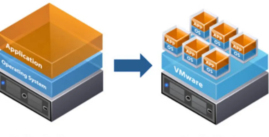
Although Singh’s definition contains technical wording, if re-phrased and re-compiled, the term becomes clear. Basically, what is meant under “virtualization” is division of computer resources to provide a simulation of multiple computers running simultaneously while having only a single real computer. Virtual computers (which are actually represented by virtual machines) act like any real computer: they have an operating system and software. Software runs within virtual machine’s operating system and it is isolated from the hardware that actually executes it. For the software to run correctly, it still usually needs some hardware, therefore virtualization platform provides some simulated hardware. There are also many other types and characteristics of virtualization, and how it can be applied, but, for the purpose of the paper, we will use this definition. As a simple explanation of virtualization, figure 1 can be used for reference: there is a simple example of how virtualization looks like compared to traditional computer architecture from a high-level perspective.
Figure 2. Desktop virtualization
Source: (Pure Storage, 2016)
Desktop virtualization is the concept of isolating a logical operating system (OS) instance from the client that is used to access it. (TechTarget, 2011) The idea behind desktop virtualization is that user uses some simple interface for accessing and interacting with a computer, which exists only virtually, running on a server connected to the interface through a network or other kind of connection. On contrary to “client-server” communication, in desktop virtualization the user doesn’t change his workflow to the new environment because all interaction looks and performs like user interacts with a personal computer, not a centralized server. As can be seen on figure 2, the overall picture resembles the same way as with more generic virtualization shown on figure 1 but, instead of
3 virtualizing some parts of a normal computer, the virtualization provider creates a full emulation of this computer.
Figure 3. Some of the characteristics of desktop virtualization solutions
Source: (Locuz, 2012)
As shown on the figure 3, there are many characteristics of what desktop virtualization provides, and, therefore why it can be beneficial for the customer. Main characteristics useful for this project and explanation why they are useful are as follows:
• independency from hardware, which includes possibility to change components of user’s virtual computer fast and a tolerance to the client’s local hardware failure (all data persists on the server)
• centralized control over client computers: all components of company’s infrastructure can be managed through a single point of access easier
4 • control over hardware resources, e.g. they can be used for other tasks during hours when there is small demand from users. For example, resources can be used for other computation tasks like scientific computation
• since all resources are at a single point, there is no need in over-estimating them because all users don’t have the highest resource demands at the same time, therefore resources can be brought more efficiently with idea that even for “peek moments” server doesn’t need the same resources as if all client computers were standalone systems, which require to have “peek” resources to be available at a client machine all the time
1.2. Customer and existing customer’s solution
The customer for the project is a group in the Valais Wallis campus of École polytechnique fédérale de Lausanne (EPFL), which is dedicated to scientific research in energetic optimization in urban systems and industrial processes. Most of the work happening in the group is research produced over long periods of time: some people work there for up to 4 years but some can work for only a few months. Normally there are up to 40 people using their desktop computers on a daily basis. Because of different timeframes when people come and go, it becomes hard to maintain all computers in a decent state and re-install environment for new users who might come for only 3 months.
Currently people working at the site use desktop computers for connecting to EPFL network and authenticating against Active Directory. Most of the users use the same applications to work on their projects and rarely install other software. Because sometimes users work on their projects for years, it is important to save user-generated information, which can be anything from a few small files to gigabytes of data requiring special software.
All computers in the laboratory have pretty much the same hardware and run within the same network, which is provided through a direct connection to the network of EPFL in Lausanne. The network speed is fast enough for accessing shared resources on internal network but it can be a problem if the whole desktop operating system should be transferred from the Internet to the user. Also, regarding network, all computers have a dynamic external IP address, which changes every 1.5 hour.
For the reason of implementing a virtualization environment a server, Dell PowerEdge R730, was purchased. It has 8 hard drives, each 1,2 terabytes in the size, 2 Intel Xeon 14-core processors with HyperThreading technology, 256 gigabytes of memory and a networking capabilities of 4 connections by 10 gigabits per seconds plus 2 network adapters capable of a speed 1 gigabit per second. Initially, that server would be used for scientific projects requiring specific virtual machines. Later on, when
5 the project completes, if the capabilities of it will be found satisfying, it will be also used as a main server for the desktop virtualization.
Main contact with the campus was Voiselle Joël Gilbert André Robert Emmanuel, who is in charge of IT in this research group. His tasks contain developing, maintaining and extending the optimization platform along with maintaining virtual machines and general IT help.
6 1.3. Problem to be addressed during the project
Because there are many new users coming and leaving the research group every few months, it is not feasible to reinstall manually operating system and all software on the desktop computer in order to have a new, clean installation on the machine for the new users. Right now all computer maintenance is done manually and it is a big problem for the IT support. Using desktop virtualization, such tasks could be automated and new users would be able to start working a few hours, or even minutes, after they request a new machine.
Also, some computations require a lot of computer power. Executing such computations on a client computer is nearly impossible because of the time required for them to complete on a regular computer. If a virtualization solution is used, these computations could be executed on a server, for example, during the night, when desktop virtualization is not used and there are free resources on the virtualization server.
The client defined requirements for the virtualized desktop computers as follows: a hard drive 100 gigabytes in size, 2-core processor, 8 gigabytes of memory.
Therefore, the problems to be addressed in the paper are as follow: create a demo of desktop virtualization platform, provide reasoning for whether this kind of solution would comply with the customer’s requirements if executed on the purchased server and define, whether it would be possible to use such a solution as a place for computational tasks of users’ projects during the night periods of time.
1.4. Project development
Although some parts overlapped with other, the project can be divided in 3 main parts, which occurred sequentially:
1. Finding, analyzing and comparing desktop virtualization solutions, which are popular nowadays. As a result of this part, one solution is selected for demo implementation.
2. Analyzing current customer’s infrastructure and how a new system would fit it. This part is iterative meaning that it isn’t possible to create, even a high-level view on how new system should be implemented, without trying to do it in different ways. All virtualization solutions today are complex systems, which interact with different parts of existing infrastructure and have different possible implementations. Since not all of the possible implementations can be achieved or be really useful for the customer, the main goal is to find a solution which fits customer’s needs within the given environment.
7 3. Process of implementing a demo of virtualization solution for testing.
Although analysis and comparison of different solutions is useful for the customer, the main deliverable of the project for company is step-by-step instructions to achieve what was done in the demo implementation. These instructions should contain enough explanation of what have been done and why so that it is understandable how to use them in case of environment different from what has been given for testing purposes for the project. The complete result of this part is in Appendix I.
8
2. CHOICE OF A SYSTEM
There are many desktop virtualization solutions on the market right now. First of all, different solutions were gathered and grouped by where they are installed: on a hardware within an existing infrastructure (standard providers) or if they are provided by a cloud platform as a service.
2.1. Groups of virtualization systems
During the process of collection of data on cloud providers it was decided to only include well-known providers with a good 24/7 support because customer asked for maintainable solution since desktop machines are critical for the company and even a few hours of outage should not occur under normal circumstances. Also, since this infrastructure would contain all information created by users, it is key that provider can be trusted on saving and maintaining the data.
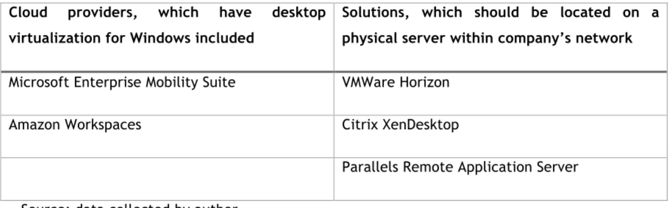
Table 1. Groups of desktop virtualization providers
Cloud providers, which have desktop virtualization for Windows included
Solutions, which should be located on a physical server within company’s network Microsoft Enterprise Mobility Suite VMWare Horizon
Amazon Workspaces Citrix XenDesktop
Parallels Remote Application Server
Source: data collected by author
Looking at table 1, first thing to note is that VMWare Horizon and Citrix XenDesktop are long-known competitors inside this market. Both of products also provide cloud solutions but they are mainly famous for their solutions for virtual desktops served from the network within the company. Other companies (Parallels, Microsoft and Amazon) are new to the market: all of them just started the business of desktop virtualization from 1 to 3 years ago but the names of the companies are still valuable within general virtualization market.
After creating the table, by combining providers by this criterion, 2 main differences between this groups become clear: how price of the solution is calculated and how the solution integrates within existing infrastructure.
For cloud providers the price is a monthly fee and for standard providers the price is the price of hardware plus the price of owning the software. If considered as a setup that is profitable to evaluate for short period of time (up to 2-3 years), cloud providers are ideal because they don’t require big
9 investments and can be cancelled any month. In a long term, it is clear that cloud providers would cost more than their competitors because their prices contain a price of renting the hardware required for virtual desktops, which is greater than buying a standalone server. As James (2015) writes: “…cloud is great for small setups but with the added complexity, you won’t get the performance/cost ratio of a dedicated server”. Also, since cloud providers are usually hard to integrate within existing infrastructure and they require some networking changes, the overall cost of ownership with them includes price of changing infrastructure and dealing with problems after those changes are made. For example, it will be hard to do user authentication users against private Active Directory with cloud providers. As for this project, implementing a demo of such a solution that would be showing how to do those infrastructural changes might not be even possible to do within a given timeframe.
For standard providers the main disadvantage is that the complete price of the hardware and software they require should be paid at the moment before implementing such a solution. Also, since standard providers integrate within existing infrastructure, they require more planning to be done and a better understanding of how they work inside. For cloud providers all internal operations are hidden: administrator doesn’t have an access to the actual hardware running virtualization platform and, therefore, this part of the job is fully outsourced to the support team.
At the moment of completing gathering information about solution providers the company already acquired a new physical server, which main goal was to enable desktop virtualization within the research group, therefore the main advantage of renting in cloud solutions was gone.
2.2. Comparison criteria of products explained
After discussion with the customer, standard providers were chosen for a more detailed comparison. Features important for the customer were selected and discussed in a matter of their importance. The importance is either “important” (red in the table) or “recommended” (green in the table). By the agreement with customer, the final solution should have all “important” features to be implemented and “recommended” features are those that can influence on the choice between systems that have all “important” features.
Linux support – along with supporting Windows as an operating system for client computers, virtualization platform should be able to run virtual machines with Linux. Mainly this is meant for running an internal web server; important feature.
Automatic environment configuration – operations like installing and configuring software on the virtual desktop should be possible to automate; important feature.
10 Stateful virtualization support – it essential that the data is being saved as long as the user needs it. For that reason, stateful virtualization is important because virtual desktop is saved between user logins; important feature.
Alerts about resource consumption overload – there should be a notification system that informs administrator about overload in server’s resources consumption; important feature.
Full-stack solution – it is best that virtualization platform and components within it come from a single provider. That way it is possible to receive support in any questions regarding virtualization from this provider and there are no cross-interaction problems within providers; important feature.
User environment management – ideally, all data generated by user (settings, files) should be possible to retrieve and re-use between virtual machines. This way it would be possible for the customer to manage virtual machines in a “stateless” mode but still provide all advantages of a “stateful” virtual machine like; recommended feature.
Connect with any operating system – client computer connecting to the virtual desktop should be able to do it from Windows, Linux and macOS; recommended feature.
GPU computation virtualization – some projects occurring within a research group may require computations running on a graphical card. Because of that, it should be possible to have an integration with graphical card systems like NVidia GRID in order to do such computations; recommended feature.
Mobile devices support – in the future it might be good for users to be able to access their virtual desktops from mobile/tablet devices; recommended feature.
11 2.3. Systems comparison and comparison conclusions
Table 2. Desktop virtualization platforms comparison
Criterion Citrix XenDesktop VMWare Horizon Parallels Remote Application Server
Linux support Yes Yes No
Automatic environment configuration
Yes Yes Yes
Stateful virtualization
support Yes Yes Yes
Alerts about resource consumption overload
Yes Yes Yes
Full-stack solution Yes Yes No
User environment management
Partiala Yes Yes
Connect with any
operating system Yes Yes No GPU computation
virtualization Yes Yes No Mobile devices
support
Yes Yes Yes
Source: data collected by author
a. “Partial” used in the “User environment management” for Citrix XenDesktop refers to the fact that this platform has a limited support of this feature: it is possible to save and restore user’s environment but this operation is used mainly as a backup – it does not integrate with “stateless” virtualization and, therefore, can’t be used in a scenario provided by the customer.
Data collected for the comparison in table 2 came from companies’ official websites and marketing materials. Because companies usually don’t like to disclose their missing features, some information was implied from the systems’ documentation.
Although Parallels Remote Application Server is an interesting solution because it is a new player on the market and it has many things done differently, it lacks two important features, which makes it not viable for this project. First of all, it doesn’t have support virtualizing of Linux operating system, which makes it unusable for customer’s requirements. Secondly, it is not a “full-stack” solution
12 because all desktop virtualization within this system happens on other provider’s platforms. Basically Parallels Remote Application Server provides only the interface and monitoring for other desktop virtualization platforms like those provided by Citrix and VMWare.
When it comes to comparison between Citrix XenDesktop and VMWare Horizon, there is no clear leader: only 1 “recommended” parameter of comparison is significantly different between these products but otherwise products provide the same features for all project’s requirements. This is mostly due to the fact that both companies have been competing on the market for years and they integrated features of each other during this competition.
It is worth noting that, although Citrix XenDesktop is considered a “full-stack” virtualization provider, many XenDesktop installations involve VMWare’s ESXi server. According to Hidalgo (2014), this is due to “simplicity of the deployment and implementation, which translates into less hidden costs”.
Although there is no clear leader among Citrix XenDesktop and VMWare Horizon, the latter one complies to requirements more precisely than the former in the part of user environment management. Also, as it turned out after the comparison, customer already used solutions from VMWare’s virtualization platform, including VMWare ESXi and VMWare vCenter Server. VMWare Horizon is built upon those two products therefore it would be easier for the customer to implement and work with this solution, which can be a big benefit. Because of this, VMWare Horizon was chosen as a main system for implementation and Citrix XenDesktop was chosen as a backup variant, in case it won’t be possible to create a demo of Horizon-powered virtualization system within the company’s infrastructure.
13
3. SYSTEM ARCHITECTURE
Since VMWare Horizon 7 consists of many virtualization solutions working together, there are many decisions to be made during setting up the system. Probably the most important decisions are architectural because system architecture is very hard to alter after it was already implemented. This kind of decisions include networking, choosing of systems and design of how those systems interact. Of course, since this paper talks about a real project, all of those decisions should be made according to the customer’s environment, without suggesting something that is not possible or hard to implement within existing computer system.
Since not all VMWare Horizon’s components limitations and features are put straightforward in the documentation, a big amount of time on the project was spent for determining what is and what isn’t possible to do with this system.
Among most notable limitations of selected system that isn’t properly described is networking. Most of VMWare’s components require a unique static IP address, which should be set up for the component’s machine before the installation. Also, as it turned out during the project, most of the components do not work well with multiple networks combined together. Since EPFL’s network is built on an idea that all computers have an external IP address, it would be a good solution to create a small separate “management” network for all servers and/or components of those servers. This kind of network would provide an additional level of security by protecting all highly valuable services which do not require interaction with normal users to be accessible only to a system administrator, who has an access to this kind of network. The first complete working system architecture planned was based on this idea. Later on, it turned out that, although it is possible to implement, VMWare doesn’t recommend to use multiple networks within its’ virtualization components, therefore other system architecture was built up, according to VMWare’s best practices and how EPFL’s network works.
14 3.1. System components
There are many components interacting within Horizon.
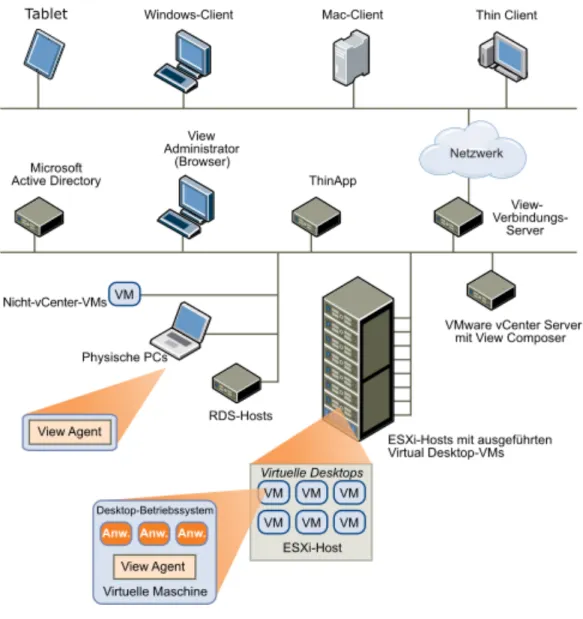
Figure 4. Components within Horizon 7 infrastructure
Source: (VMWare, 2016)
The picture in figure 4 contains a high-level representation of all main components in VMWare Horizon 7 infrastructure: Client devices represented by tablets, thin clients and other kinds of user computers, View Connection Server, vCenter Server, ESXi Host and Active Directory. Also it contains additional components like ThinApp and View Composer, which are not essential and can be added later.
15 All of the main components, on the other hand, are important to be analyzed because their correct implementation is the goal of the demo for the project.
3.1.1. Active Directory
Active Directory is used throughout solution’s virtualization platform for system configuration and user authentication. First of all, Active Directory can be used as a DNS server so that some of the components within the company’s intranet are at least accessible by their unique domain name and not just their IP address. Secondly, Active Directory can be used in vCenter Server as a main authentication method because this way there is no requirement on creating separate user profiles inside vCenter Server for different user roles – user accounts will be centralized and managed in the Active Directory.
Third and main role of Active Directory within VMWare Horizon is View Connection Server. This component uses Active Directory both for user authentication and computer configuration. Since all virtual desktop computers should comply to policies of the internal organization’s network, View Connection Server uses existing Active Directory infrastructure for that goal. To access their virtual desktops, all users authenticate using their Active Directory credentials. Based on those credentials, View Connection Server can determine whether user is allowed to use the virtual machine and what are limitations and features given to him based on Active Directory’s Group Policy Objects and View Policies defined inside View Connection Server. VMWare also provides Group Policy Objects rules templates so that features specific to View Connection Server-provided machines are also possible to be configured.
Active Directory is a part of the system, which should be hosted outside of the main server. Since Active Directory already exists within company’s infrastructure, the existing system was used for the purposes of the project.
3.1.2. ESX Host
ESXi Host is a main server inside the virtualization platform. Its’ purpose is to run virtual machines prepared and executed by other servers or clients. The main networking requirement for it is that it should have a dedicated static external IP address to be available to other components.
3.1.3. vCenter Server
vCenter Server – main virtual machine execution server. It is used to administer virtual machines on an ESXi Host and provides services for other more high-level execution servers and components to run and manage their own virtual machines. vCenter Server is central to VMWare’s desktop virtualization because it is a big part of an overall architecture. Also, vCenter Server contains
16 different components which can be installed together or independently. For example, one of such a component is “Single-Sign On” – unified way of user authentication within the VMWare virtualization solution. vCenter Server should have a dedicated static external IP address to be available to other components and system administrator. It can be run inside the ESXi host it manages, therefore making it easy to
Figure 5. Selected "recommended topology" from VMWare for the vCenter Server
Source: (VMware, Inc., 2016)
As for the vCenter Server installation, because this component itself contains multiple parts described above, VMWare has different topologies recommended for installation. (VMware, Inc., 2016) Since the goal of this paper is to provide simple yet working solution, the first recommended topology was selected: one Single Sign-On domain with one Single Sign-On site and one vCenter Server with embedded Platform Services Controller within a single virtual machine. This topology supports all of the features of vCenter Server, including possibility to backup and restore configuration, and doesn’t require many steps to be followed.
Depending on the company's needs, installation should be adjusted accordingly: vCenter Server's database, instead of using built-in vPostgres, can be moved to an external Oracle database. According to VMWare, this is not the case for the customer right now, because limitations of vPostgres are relatively big:
vPostgres on windows is limited to 20 hosts and 200 virtual machines. Upgrades where SQL express was installed will be converted to vPostgres. The vCenter Server Appliance supports embedded vPostgres at full scale, 1000 host and 10,000 virtual machines and is the recommended database for the vCenter Server appliance. (VMWare, Inc., 2015)
3.1.4. View Connection Server
View Connection Server – desktop virtualization server, which is in charge of all operations tied with desktop virtualization inside VMWare’s platform. It provides administrating interface for all desktop and application virtualization services, maintains virtual desktops and acts as an information
17 broker between virtual desktops and client workstations. It also should have a dedicated static external IP address to be available to other components and users.
3.1.5. Client workstation
Client workstation is an interface for displaying and providing interaction with a desktop virtual machine. It can include anything from a smartphone to a Mac computer, including “thin client” computers. The workstation should be on the same network as View Connection Server but otherwise it doesn’t have any networking requirements.
3.2. Different approaches to implementing system architecture
Desktop virtualization systems, due to their complexity, can be created completely different and their architecture mostly depends on how the network in the company works and which hardware company owns. Probably because of that, VMWare doesn’t have any “reference” implementation of the overall system and the only complete picture of Horizon 7 architecture is shown in figure 5. Therefore, all components first should be understood one-by-one, how they work and what do they require. Only then they can be connected together by a system administrator. In the case of this project, the author of the paper was in charge of this work. After understanding all components and their requirements, and after applying customer’s computer environment on those components, 2 different system architectures were proposed as a result.
18 3.2.1. First architecture
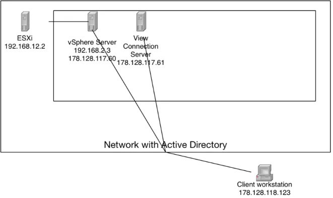
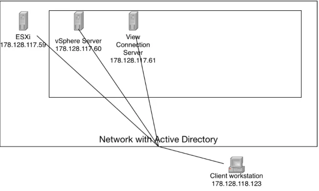
Figure 6. First system architecture design
Source: image produced by author
On the figure 6 first system architecture plan is shown: network connections are represented with lines, nesting of systems is represented with boxes near the “parent” systems and examples of IP addresses are given under the components.
Initial architecture design was done according to VMWare’s “ESXI Networking Security Recommendations” in the “vSphere Installation and Setup” document. As this document states: “A management network isolates client traffic, command-line interface (CLI) or API traffic, and third- party software traffic from normal traffic. This network should be accessible only by system, network, and security administrators.”. (VMware, Inc., 2015, p. 168) The term “management network” here is used within VMWare’s ESXi server terminology and refers to the main network where ESXi is accessible. Therefore, the main idea behind this recommendation is that ESXi should be placed on a separate network, which is accessible only by server components which require access to it. In the case of this project, the only component requiring direct access to the ESXi was vCenter Server. All other server components, including vCenter Server and View Connection Server, should be placed on a static internal network.
19 ESXi is the only main component where authentication is only possible using a standard password. Other components provide ways to ensure security by extending it with, for example, Active Directory authentication or other secure authentication mechanisms. Because of that, it made a perfect sense to implement such an architecture.
Figure 7. vSphere Web Client - Remote Console feature
Source: author’s screenshot
Although initially this design seemed to be possible to achieve, it turned out that this is not an easy task to be done. After implementing such an architecture, multiple problems occurred. First of all, some parts of vCenter Server assume that ESXi is managed through the same network as the network through which user accesses vSphere Web Client. As a result, it is not possible to use features like “Launch Remote Console” inside vSphere Web Client, shown on the figure 7, because the application launches using that button tries to reach ESXi by an address in the private network. Also, there are some communicational problems occurring between vCenter Server and ESXi when using this architecture: connection may drop any time and restoration may or may not be possible.
As it turned out later, the last problem was due to how network routing is built within vCenter Server: it considers all networks connected to as they are the only main network and routing is configured through the first network, which vCenter Server finds. I wasn’t the only one who stumbled at that problem. According to Lam (2016), VMWare doesn’t actually support this kind of scenario for vCenter Server: “Although it is possible to add additional vNICs to the VCSA, as far as I have been told, this is currently not officially supported by VMware.”. In the article mentioned there are ways describing how to overcome this limitation but they require a good knowledge of Linux operating system and how networking there works. Also, since it’s not a standard scenario, VMWare probably won’t support such a configuration. Because of that, this system architecture was dropped in favor of a second one.
20 3.2.2. Second architecture
Figure 8. First system architecture design
Source: image produced by author
As seen on the figure 8, the second architecture looks not very different from the first one. From a high-level perspective, which is shown there, only one network connection changed: ESXi now connects straight to the network and not to the vCenter Server.
This change on the high-level picture of infrastructure actually changes a lot. First of all, ESXi gains networking communication and, therefore, receives an ability to synchronize time and data with an external network. Secondly, with this change, computers other than vCenter Server are able to communicate with the ESXi. This is convenient because, for example, if vCenter Server fails to start for some reason, there is an easy way to evaluate what have gone wrong without needing a direct access to the private network between ESXi and vCenter Server. Thirdly and mainly, this change fixes the problem mentioned in the first system architecture design: vCenter Server now has only one network.
Of course, this change comes with constrains. Mainly it makes ESXi the most vulnerable component in the system because authentication constrains in ESXi are not very configurable (only a single password exists) and also because ESXi becomes a single point of failure: if, for example, a
DDoS-21 attack targets it, there is no possible way to access any of the virtualization resources through the network.
To implement this architecture, a new installation of the system was carried out because there is no way to reconfigure the networking in such a way without breaking a connection through which the reconfiguration occurs. During a few weeks this installation was working without any troubles concerning system design, which was not the case with the first system architecture.
22
4. SYSTEM IMPLEMENTATION
After finding and testing the optimal system architecture, which complied to the customer’s requirements and performed well over time, the system implementation phase of the project started. During this phase all information gathered about VMWare’s virtualization platform and specific configuration required was applied to provide the testing environment. Also, while implementing the demo system, installation instructions were created, which included step-by-step instructions on how customer can implement the same system. These instructions are meant to provide sufficient information to not only replicate the demo environment but also to explain critical parts of the installation and reasoning of why certain configuration was chosen for each of the components. They are included in Appendix I. This chapter is only the summary of the final system implementation process.
For using the platform, client software is required to connect to the virtual desktops. A tutorial on using different approaches for that was created so that users can test the demo implementation. It is included in Appendix II. The tutorial was built the way that, when the system is implemented for real, there are only a few changes that are required for this tutorial to be re-used with the production system.
4.1.1. Preparing the hardware
First of all, BIOS settings on the hardware should be configured. The main options are boot settings, which depend on the hardware, and time settings – the time on the server should be set correctly and in the UTC time zone. This is important because otherwise conditions may occur, when new operations happening in ESXi will have time set earlier than operations that already occurred before. This kind of situation can corrupt the whole system.
Secondly, network interfaces should be configured properly. The server needs at least two network cards: first card should be connected to a static network and the second should be connected to a DHCP server-enabled network.
4.1.2. Setting up ESXi.
After writing ESXi installation image on a CD or USB device, the process of ESXi installation is straightforward: most of the options when installing on a fresh hardware have only one value and the most important setting is selecting a correct “Management Network” for ESXi. Since “Management Network” is a network through which clients connect to ESXi for configuration and accessing virtualization level, it is best to set a static IP address to it. Therefore, the correct setting for it is
23 the first network card. The second option, which should be set up properly is the “root” password for the system. It is best to set strong password of at least 12 characters long.
After installation completes, the management network should be properly configured. Since we are only using a static IPv4 address and already selected network card(s) for the management network, we need to supply information about ESXi’s IP address information. Another option to be taken in account is “DNS Configuration” – here we have to supply information about computer’s hostname and DNS servers. For easier ESXI’s integration within the network, it is recommended to set up DNS servers of the network’s internal Active Directory.
Figure 9. ESXi vSphere Host Client administrative panel
Source: (Smith, 2016)
When configuration is finished, to ensure that everything works fine, we can go to the server’s IP address in a web browser and see the ESXi’s vSphere Host Client shown in the figure 9.
24 4.2. Setting up ESXi using vSphere Client
Figure 10. vSphere Client main window
Source: author’s screenshot
To properly configure the second (DHCP server-enabled) network and time synchronization, a connection from vSphere Client application (shown on figure 10) is required. After installing the software on the administrator’s computer a connection to the ESXi should be done. Since by default all server components use self-generated SSL certificates, a warning about an untrusted certificate should have been suppressed. After that, a second network was created with the previously unused network interface assigned to it. Also, NTP servers were configured in order for ESXi to synchronize time from the network.
4.3. Setting up vCenter Server
vCenter Server comes in 2 editions: a standalone appliance and a server application installed in Windows Server. During the system architecture phase of the project, the appliance edition was selected. The appliance was installed on an ESXi host. After installation, the ESXi host was added to the hosts that are managed by the vCenter Server.
25
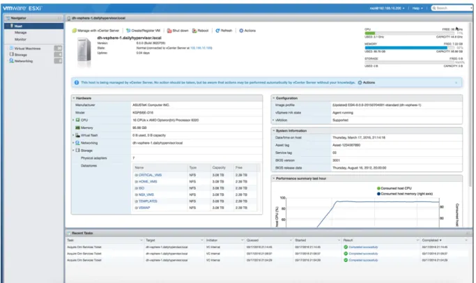
Figure 11. vCenter Server with ESXi host added
Source: author’s screenshot
When everything is done and ESXi host was added, the “Navigator” in vCenter should look like it is shown in the figure 11.
4.4. Setting up Horizon View Connection Server
First of all, to implement a View Connection Server, a virtual machine with Windows Server was set up created inside vCenter Server. The View Connection Server has been installed on this virtual machine and set up for connection with Active Directory.
After that vCenter Server was added to the View Connection Server. Within vCenter Server a “master” virtual machine was created for the virtualized desktops. This machine was configured so that it is connected to the internal Active Directory, updated and optimized for using as a virtual desktop. With that done, Horizon Agent software was installed for the View Connection Server to be able to communicate with the “master” virtual machine.
26
Figure 12. Horizon View Connection Server with desktop pool installed
Source: author’s screenshot
The last step in configuring Horizon View Connection Server was the process of converting “master” virtual machine to a template and creating a “Desktop Pool” backed by this template in Horizon View Connection Server. After setting up users, who are able to access virtual machines, the implementation was complete and Horizon View Connection Server should look like on figure 12. 4.5. Testing the implemented system
The computer, on which testing environment was installed, didn’t have a big amount of computational power and, after installing all server components, had about 8.5 gigabytes of free memory, 4 free CPU cores and 90 gigabytes of free disk space. Because of that, to measure virtualization overhead on resources, two different tests were performed.
27 First test was focusing workload and how much additional resources virtualization takes up from the platform for each virtual machine. The test included 1 virtual machine, which have assigned with 4 CPU cores and 8 gigabytes of memory. When this virtual machine was working under heavy load, up to 95% of all resources were used on the server and notifications about low resources occurred in administrative panel of vServer Center. The virtual desktop still performed normally and there was no lag or other kind of problem. Therefore, the impact of virtualization is very small on the additional resources usage in terms of a virtual machine.
During the second test, since the first one performed good, concurrency was the main concern. For that, 2 virtual desktops were created instead, each of them having 2 CPU cores and 4 gigabytes of memory. For simulating 2 client users, connections through a browser and Horizon Client to the virtual desktop were performed. During the test, once again, no problems were encountered.
Since the client of a project also wanted to test the environment, virtual machines made for the second test were once again re-created and this environment, along with instruction for testing users, were given back to the customer.
28
5. PROJECT MANAGEMENT
Project management is an important part of the project because organization and planning steps that had to be made in order to achieve success. With help of planning project ahead it was possible to make right decisions regarding goals at each stage of the project and manage technical problems occurring during the project.
5.1. Project organization (methodology)
The process of project development was iterative: every few days, depending on the complexity of current iteration, completed tasks were reviewed and, if some of those were not possible to achieve within the estimated deadline, a re-evaluation of them was done in order to take actions and fix the overall project flow. As a result, during the project, something similar to Agile methodology was used although there was not a lot of documentation because there was no requirement on that in the project’s goals.
5.2. Communication with the customer
All meetings with the customer were organized in person by a special appointment. The main goal of meetings was to gather customer’s feedback on the current progress of the work done and to get requirements regarding next stages. These meetings were only organized during early stages of the project, when there only theoretical parts were done. All important information from meetings was noted.
Along with meetings, questions about requirements and company’s infrastructure, which didn’t require explanation, were asked by e-mail. All important information from e-mail conversations was also noted so that nothing is missed and the result of the project would meet customer’s expecations.
5.3. Maintaining tasks
Most of the tasks on the project were sequential, therefore all tasks were placed in an ordered list where each preceding task was required to be completed before the task coming after it. This way it was easy to not only understand current state of the project but also, when changes were required, to re-organize the list and see new priorities.
The tasks in the project could be divided on “milestones” and normal tasks. “Milestones” were the big tasks, without which completing the project was not possible. Normal tasks are the tasks happening inside the “milestones”, which by itself are not so important and most of them can be substituted if they were not possible to achieve. Normally all tasks should have been done but some
29 tasks, due to changes in planning and problems occurring during the demo implementation, were partly dismissed
5.4. Work organization
Most of the work was done alone because this project is not a group work. Normally I started with gathering theoretical information on a task by reading system’s documentation and other information sources. After understanding main requirements and steps to achieve the task, I started implementing it and documenting implementation’s steps that were successful. Sometimes, when there were technical difficulties, which I couldn’t resolve myself due to technical limitations, which I couldn’t overcome because I didn’t have access rights or required materials, I asked the customer for help. This way it worked very well because I tried to do it as a last resort, and, as I think, I didn’t create any excessive anxiety from my presence.
5.5. Discussion on the results between iterations of tasks
After implementation part of the project started, on one hand, there was no need in special meetings with the customer because most of the questions were answered before. On the hand, many small questions on how to implement the demo of the system started to come up. Especially this questions occurred at times when one task was already finished and the other one was on early stages of development. If it was possible, to provide customer with a context of the question, I demonstrated or described what was achieved until that moment and why I am asking this question. This way I could get both answer to my question and some feedback on what I have done to the moment. Since usually we were in the same office, there was no need to organize any special meetings for that and it occurred on a daily basis.
30 5.6. Release roadmap
Figure 13. Burndown chart
Source: author’s image
The burndown chart (shown in figure 13) represents how much hour were spent during each month on the tasks related to the project. Of course, this is only a rough estimation but it gives a hint on how the work was distributed and whether all tasks were completed.
At the end of the project, all main tasks were done and the solution (demo implementation) was presented to the customer. Since the solution was accepted and it contained all tasks from the release roadmap, the burndown chart in the figure 13 ends at a point 0.
Because first two months’ time devoted to the project work was shorter than in the third month, almost half of working hours (160 from 360) spent on the project belong to the last month of work. Partly this is also because during first two months of work there were technical difficulties not all of which were expected and, in the result, I did less tasks than I planned. Due to this, during first two months of work, I have done about a 25 hours of work less than I planned.
31
6. PROJECT REALIZATION
The whole project took almost 3 months to complete. Each month there was a meeting with coordinator to inform him about current status and what have been done within the month.
6.1.1. First month
A meeting with a customer was conducted long before the project started, initial goals were set in advance. Because of that it was possible to start the project and have communication with the customer via e-mail.
For the first two weeks theoretical data on virtualization providers was gathered and compared. After that, a first meeting with the customer was conducted. During that meeting we discussed information I found on virtualization providers and agreed on the comparison criteria.
The problem at this stage was that during initial requirements gathering there was no hardware purchased and, therefore, it was agreed that all virtualization providers should be equally compared. During the meeting it turned out that the hardware would arrive soon and there is already no reason to use this kind of providers within comparison. The solution for the problem was to put aside cloud providers and, since requirements changed, find more information on standard providers because part of the criteria were based on the type of the provider.
For the next two weeks the main goal was to finish comparison and start analysis of customer’s infrastructure projected on the chosen virtualization solution. At this stage communication with the customer was made via e-mail. One of the risks were deadlines: because of the changed requirements and the fact that customer needed time to provide hardware for testing and demo implementation. This risk was undertaken without big problems because customer provided hardware just on time after the comparison was finished.
When it came to analyzing customer’s infrastructure, initial time estimations were wrong. Mostly it was due to the fact that I didn’t know much about how EPFL’s network and authentication works and my assumptions, mostly, appeared to be wrong. Of course, this kind of problems are common within and I expected that. Because the amount of work required to implement a demo was not clear at the start of the project, and during first month I understood that it would be harder than I thought, a demo of a second system, which was planned as an optional task, was dropped from the list of tasks. Also, there were hardware limitations: from what I understood, Citrix XenDesktop required at least 2 hardware servers and I had only 1 computer which I could use for it.
32 6.1.2. Second month
At the start of the second month I had to finish analysis of company’s existing infrastructure and start to gather information on what had to be done to implement a demo within it.
Main parts of the infrastructure became understandable to me after a first week of analysis conducted in the previous month, therefore this month I first started with gathering information about components of VMWare virtualization platform.
Figure 14. Horizon 7 Connection Server installation wizard
Source: author’s screenshot
During analysis of server components, I first read documentation about them and then tried to implement them according to documentation. Since Horizon (View Connection Server component) is the actual system that is in charge of serving virtual desktops, I decided to go with it first. As it turned out, there are many dependencies for View Connection Server to be properly installed (installer is shown on a figure 14): it requires a separate installation of Windows server, joining computer in the Active Directory and creating accounts for the desktop virtualization-related administrators, users and computers inside the Active Directory. Because I didn’t have administrative rights inside EPFL’s Active Directory, I first tried to simulate their environment by creating a local Active Directory installation on the same computer. It wasn’t clear from the documentation but, when I tried to do
33 this, I met one of the first restrictions: it is not possible to have the same computer being the Active Directory server and a View Connection Server.
Because I was limited on hardware, there was a problem of running Active Directory on a separate machine like it was required from the VMWare’s documentation. I’ve thought about my alternatives and there were only two available at the time. First alternative was to create the whole system inside a virtualized environment. The second alternative was to gather all information, what was needed to from Active Directory by the virtualization platform, create a plan, how these requirements could fit within EPFL’s policies (it is obvious that I couldn’t have, for example administrative rights on real computers and users inside it) and ask customer whether my plan is possible to implement inside their Active Directory. When I weighted my alternatives, I decided that, although emulating EPFL’s network is not a very hard thing to do, since I don’t know all of the caveats, I can miss with my assumptions and instructions for system implementation will become useless. Therefore, I first went with the second option and asked customer for enough rights so that I could test the system inside of the Active Directory in the EPFL network. As usual, Joёl was fast to process my request and I got everything I needed on the next day.
Another big problem I had with View Connection Server installation was also misrepresented in the documentation. Normally, for all components, VMWare allows to use dynamic IP addresses assigned by a DHCP server combined with or without DNS names for the computers. Although it is not very recommended for a production system, for the testing it seemed to be enough because at the time I had no access to a static IP address inside the EPFL’s intranet. When problem with Active Directory requirements from the View Connection Server was resolved, I received another error from the installation wizard (figure 14). As it turned out, View Connection Server was different from other server components in a way that it always enforced a requirement on a static IP address configured for the machine it runs on. When I tried to fix the issue with assigning a DHCP server-provided IP address as a static address for the machine, EPFL network stopped responding on any network requests. When I contacted the customer on the behalf of acquiring static IP address for the server, I understood what was the problem: the networking in the internal network was working different from what I expected and static IP addresses are only possible to be acquired on another, dedicated network.
When I fixed all problems mentioned, I was able to understand View Connection Server and other components of the virtualization platform became more clear to me. Therefore, I started to work on the first system architecture and tried to implement it.
34 6.1.3. Third month
During the third month I found that my first system architecture didn’t work as I expected – there were constant problems somehow related to networking. After digging on the subject in search engines, I found an article describing my problem and solutions for it. After that I was able to create a second system architecture, which was working fine and proved to be stable.
Next, after contacting customer, I gained additional information on virtual desktops configuration and started the last part of implementation. The only problem, which occurred during this process was the required operating system on the virtual desktop. Once again, it is not mentioned in the documentation but not all editions of Windows operating systems are supported by VMWare Horizon. Since I had no access to “Enterprise” editions of those operating systems, I asked the customer for a help and he provided me with the required file.
When implementation was done, I first tested it myself, using two techniques that I could imagine and then I presented it to the customer. Since everything was working as expected, we agreed on that I would re-create the testing environment so that real users would be able to test it with their accounts.
35
7. CONCLUSIONS
7.1. Work conclusion
As a result of the study different desktop virtualization platform were reviewed and compared. The final implementation of a system requested by the customer was done and tested. During the workload test it was proven that the solution’s virtualization platform impacts very small on how much additional resources it takes up for each virtual machine to run. The virtualization platform itself (vCenter Server and View Connection Server combined), according to system requirements, should not take more than 18 gigabytes of memory and up to 8 computer cores. Therefore, it was proven that the server purchased by the company for the virtualization platform should be enough to provide at least 40 client virtual desktops with only a small resource overlap between the machines. As for possibility of executing tasks not related to desktop virtualization, for example, computations, this is also possible because the whole solution runs on a generic virtualization platform (ESXi), which can also be used for such tasks.
It is important to note that the solution was accepted by the client because it conformed to all of his requirements and did exactly what was asked.
7.2. Possible improvements
Systems like VMWare Horizon are very complex and always have things to be improved. The work done during the project was limited in time and available resources. Because of that, in the resulting solution and project work itself there are already several things that could be improved if the project would be continued.
First of all, a look at system redundancy should be made because right now this system by design is a single point of failure. Of course, platforms like Horizon are well-tested and have millions of users world-wide but there are still some concerns on a possibility of a system failure, which would result in all desktop computers not accessible to the users. The redundancy itself is a large topic and it requires additional resources, like another server of the same configuration and a load-balancing server between this two servers, to be acquired.
Secondly, in a production system, SSL certificates should be set up for the servers to be accessed without SSL warnings.
Thirdly, VMWare’s features like Instant Clone combined with User environment management should be reviewed more closely because they can provide even more resources savings while giving abilities to modify users’ virtual desktops on-they-fly, without requiring users to manually backup and restore information they created.
36 7.3. Personal conclusion
As for me, this was a great experience of working inside a modern company that has resources and a willingness to change and evolve. This project gave me not only knowledge in virtualization platforms and other related technologies, it also provided me with an interesting situation where I had to analyze and understand a complex (for me) infrastructure, which serves for thousands of users every day. I had nice people helping and access inside a research group that I would never be able to visit in other cases. I would be glad if something like this would happen to me again.