A Collaborative Environment for Distributed Web-based
CAD
by
Gangadhar Konduri
B.Tech(Hons), Indian Institute of Technology, Kharagpur (1997)
Submitted to the Department of Electrical Engineering and Computer Science
in partial fulfillment of the requirements for the degree of
Master of Science
at the
MASSACHUSETTS INSTITUTE OF TECHNOLOGY
February 1999
@ 1998 Massachusetts Institute of Technology. All rights reserved.
The author hereby grants to MIT permission to reproduce and distribute publicly
paper and electronic copies of this thesis document in whole or in part.
A u th o r ...
...
.... 0 ...
Department of Electrical Engineering and Computer Science
December 18, 1998
Certified by...
I...
...
Anantha Chandrakasan
Associate Professor of EECS
Thesis Supervisor
Accepted by ... .
~..m~~
ArthuV C. Smith
Chairman, Department Committee on Graduate Students
A Collaborative Environment for Distributed Web-based CAD
by
Gangadhar Konduri
Submitted to the Department of Electrical Engineering and Computer Science on December 18, 1998, in partial fulfillment of the
requirements for the degree of Master of Science
Abstract
The increasing complexity and geographical separation of design data, tools and teams has created a need for a collaborative and distributed Computer-Aided Design environment. The high integration levels call for tools and generators that allow the exploration of the design space irrespective of the geographical location of the design tools.
The World Wide Web serves as a desirable platform for distributed access to libraries and design tools. The web has several properties that can provide an important platform for
VLSI CAD, when combined with distributed object technologies and platform independent
languages. In this thesis an environment for collaborative and distributed Web-based CAD is presented. In this environment, the designers can efficiently utilize the capabilities of existing design tools on the Web and also build hierarchical Web-tools in a collaborative fashion. The environment includes a Java hierarchical collaborative schematic editor and the required interfaces to distributed Web-tools and cell libraries. The environment also includes the infrastructure to store and manipulate design objects and the protocols for communication with tools, message passing and collaboration.
Thesis Supervisor: Anantha Chandrakasan Title: Associate Professor of EECS
Acknowledgments
"
I would like to express my deepest gratitude to my advisor, Anantha Chandrakasan, for his support, guidance and suggestions throughout the project. Anantha has always inspired and motivated me. It has been a wonderful experience to have him as my advisor." My sincere thanks to Debashis Saha, who helped me throughout the project with his
inputs about WebTop and other issues.
" My thanks to all my office mates, Duke Xanthapoulos, Jim Goodman, Seonghwan
Cho, Raj Amritharajah, Wendi Rabiner, Vadim Gutnik, Joshua Bretz, Amit Sinha, Alicia Wong and Scott Meninger for providing a wonderful environment to grow and develop myself.
" I gratefully acknowledge DARPA for supporting my graduate study.
" And most importantly, I would like to thank my parents and my brother for their
constant support, love and encouragement. Their blessings and sacrifice have made this possible.
Contents
1 Introduction 11
1.1 Challenges in designing "Systems-on-a-chip" . . . . 11
1.2 The Web and the Internet . . . . 12
1.3 The model of Web-based CAD . . . . 13
1.4 The Distributed Microsystem Design Framework, WebTop . . . . 15
1.5 The Collaborative environment . . . . 16
1.6 Related W ork . . . . 17
2 Web based Technologies and Java 19 2.1 The Hypertext Transport Protocol . . . . 19
2.2 The Common Gateway Interface (CGI) . . . . 21
2.3 Java Programming Language . . . . 22
2.3.1 New Features in Javal.1 . . . . 24
2.4 Distributed Object Technologies . . . . 25
2.4.1 Java R M I . . . . 26
2.4.2 Java Serialization Mechanisms . . . . 27
2.5 Sum m ary . . . . 28
3 Design Example with the Distributed Tool 29 3.1 The Distributed Web-based CAD tool, WebTop . . . . 29
3.2 Adding new cells to WebTop . . . . 32
3.3 Interaction with tools . . . . 36
3.4 Saving the designs . . . . 37
4 The Collaborative Environment 41
4.1 C ollabTop . . . . . 41
4.1.1 Client-Server Architecture ... ... 42
4.2 Higher Level Issues . . . . 44
4.2.1 Synchronization . . . . 45
4.2.2 R ecovery . . . . 48
4.2.3 Locking . . . . 49
4.3 Implementation Details . . . . 50
4.4 Example Collaborative Flow . . . . 53
5 Summary and future work 59
List of Figures
Distributed CAD Environment . . . . WebTop: The distributed framework . . . . The Concept of the Collaborative Environment . . . .
The components of a simple WWW interaction . . . . Java language and its APIs . . . . The Java RMI Mechanism . . . .
3-1 Data flow in Hierarchical tools . . . .
3-2 A snapshot of WebTop's schematic editor and Library Manager .
3-3 WebTop and Various tools . . . . A 2 input 1 output prototype cell with Verilog and
A cell including a prototype cell in its schematic .
Steps involved in the DC-DC simulation . . . . .
Concept of the Collaborative framework . . . . . Collaborative design with several sessions . . . .
Client-Server and Peer-to-Peer Architecture . . .
Synchronization of the System . . . .
An example of mouse movements where locking is Snapshot of the Collaborative framework . . . .
Client-Server Architecture of the System . . . . . Example flow in the Collaborative framework . .
Spice views
required
A-i The Schematic of the media processor
A-2 The netlist from the media processor that is submitted to PowerPlay .
1-1 1-2 1-3 2-1 2-2 2-3 . . . . 14 . . . . 15 . . . . 16 . . . . 20 . . . . 23 . . . . 27 3-4 3-5 3-6 4-1 4-2 4-3 4-4 4-5 4-6 4-7 4-8 31 32 33 34 35 40 42 43 44 48 50 55 56 57 . . . . 6 1 62
A-3 The snapshot of PowerPlay after it receives the netlist from WebTop . . . . 63
A-4 The output of Stanford Power Simulator and the netlist from WebTop . . . 64
A-5 The Schematic of the IDCT chip submitted to Pythia . . . . 65
A-6 The verilog netlist of IDCT chip . . . . 65
Chapter 1
Introduction
In the design of large integrated systems, design teams use various CAD tools that is distributed across several sites. The tools used in the design process might be situated in different locations. Such distribution of tools and the data calls for a framework facilitating distributed design. Diverse expertise is required at various levels of abstraction during the design process, and the design teams are expected to be geographically separated, requiring that the design environment be collaborative in nature.
1.1
Challenges in designing "Systems-on-a-chip"
Deep submicron scaling enables integration of tens of millions of transistors on a single chip, allowing the implementation of an entire system on a chip. Such a design of "systems
-on - a - chip" increases both the complexity of design and the issues of management in
the design process. CAD tools that are capable of handling the increased complexity are required to design such systems. Making tools that integrate these large designs and that efficiently test and verify them is a major challenge.
Modular approach helps in easier and better management of the designs. These complex chips consist of various modules requiring diverse design knowledge. Reuse of existing modules and libraries in the design helps significantly in the design process, by reducing the design time and by simplifying the design.
Therefore, there is a need for a design environment exhibiting the following properties:
9 It simplifies the design process, as seen by the user, by automating design flows and by allowing collaboration among the users.
" The environment gives collaborative access to the remote libraries and design tools, at all levels of design abstraction, with simple and standard user interfaces.
" It enables a modular/hierarchical approach to the design.
Such a requirement motivated us to develop an environment that facilitates collabo-rative, distributed and hierarchical design. The WorldWideWeb(WWW) provides a nice channel of communication required for the tool.
1.2
The Web and the Internet
The advent of Internet has opened new vistas in the area of collaboration. The WWW has emerged as the most desirable platform for distributed access to information. The Web can serve as a very attractive platform for distributed applications because of the following reasons:
" The protocols and mechanisms of WWW are simple and do not rely on the underlying
hardware.
" The popularity of the WWW is mainly due to its simple and standard browser
inter-face. This means that many users are already familiar with a friendly user interface that WWW has to offer.
" The limitation of only server-side computation of the WWW using form based CGI
programming has been alleviated with the emergence of a platform independent pro-gramming language, Java. Client-side processing can be done through the Java ap-plets.
" The limitations of state-less connection are also overcome with Java as a full
program-ming language being integrated in the browsers.
" The Object technologies and the Java serialization mechanisms facilitate the easy
communication of large data between clients and server and among different clients.
" The WWW has also emerged as a strong platform for remote access to tools, enabling
Java applets can be embedded in the webpages and therefore the designers can use their browsers to use the tools implemented as an applet. All these factors, along with the advantages of Java, make the WWW an ideal platform for collaborative and distributed micro-system design.
1.3
The model of Web-based CAD
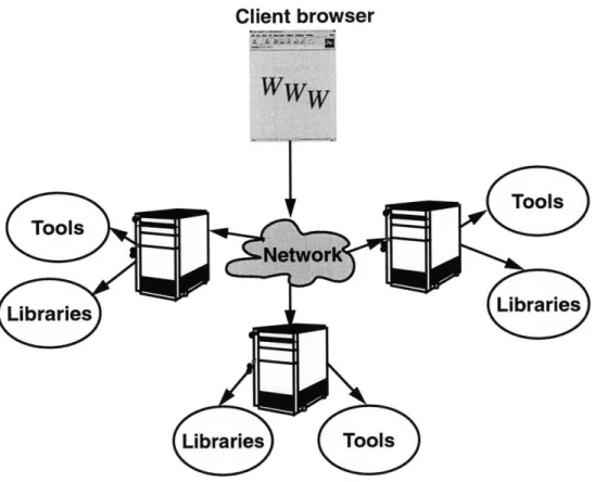
The World Wide Web has led to a paradigm shift in the research, development and integra-tion of EDA tools. Web-based CAD poses to define a new era of electronic design in which tools, models and cell libraries are accessible from any remote location. VLSI design in-volves many compute-intensive steps like simulation and verification. These jobs should be executed nodes on the network with significant computation power. Typically, server-side computation meets such requirements, and less compute-intensive jobs can be performed at the client end. A Web-based framework should optimally partition the client-side and server-side jobs efficiently. It should integrate the tools seamlessly in the framework. At all levels, it should allow the designers to collaborate in the design process.
In the model of Web-based CAD, the designers use a Web browser on their desktop and access cell libraries and design tools irrespective of their location. The designer can also collaborate in the design process. The tool utilizes the existing cells and tools from different places without the user having to install these locally. This is a design-centric approach, with the designer at the center of the methodology and the tool takes care of the distributed
access.
The following are the various aspects of Web-based CAD that are fundamentally different from the way VLSI design is done today:
" No installation of CAD tools: Web-based CAD does not require any client end
installation of tools. Tools are either downloaded via internet or the input is sent to the server, where the tool is executed. The location of the tool on the Web and the interfaces of the tool are required for accessing it through Web-based CAD framework.
" No Maintenance: It reduces the maintenance cost of the CAD tools. The latest
version of the tool can be maintained and distributed by the vendor at their site so that the designer can use it. Currently, much of the designers' effort go into tool
Client browser
Figure 1-1: Distributed CAD Environment
installation and maintenance in terms of version controls, license controls etc. Since all of the burden falls on the vendor with web-based CAD, the designers are simply left with the use of the tool in this framework.
" Access to Powerful Computers: Many CAD tools require extensive computational
power, which many small designer houses cannot afford to have. With the server based computation of Web-based CAD, users could make use of the high performance computing power of the servers.
" Pay-per-use CAD: Making tools available on the Web will allow tool vendors to
use a pay-per-use model.
" Ease of Collaboration:The framework creates a collaborative environment so that
the designers could easily cooperate in the design process.
col-laborative framework in a distributed design environment. The WWW can help better utilization of resources through distributed design and in bringing together team of experts from all over the world into the design space through collaboration. The information ex-change between the tools should be efficient in this framework to make effective use of the wide variety of tools available.
1.4
The Distributed Microsystem Design Framework, WebTop
A distributed design environment, WebTop, has been developed at M.I.T. It is a
web-based CAD framework providing all the advantages mentioned in the previous section. The environment makes it easier for the designer to use the tools or data without having to think about their physical location and versioning.
Client
Server
Design
Prediction
Entrv
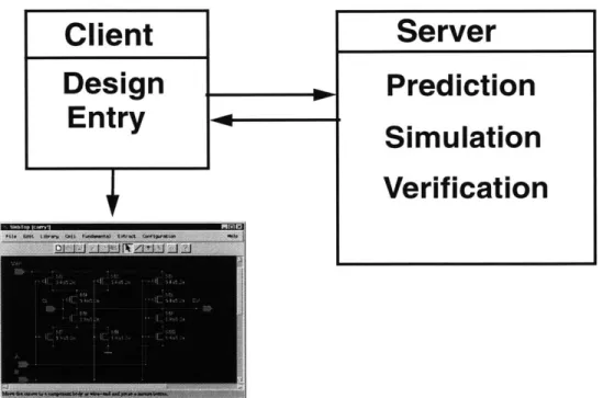
Figure 1-2: WebTop: The distributed framework
The entry point for the design is a schematic editor that supports hierarchical design. WebTop is capable of accessing cell libraries located on different servers through the internet. The users can extract the netlist, that conforms to the input specification of several web-tools, from their design. They can submit such a netlist to the corresponding webtool and view the results. The tool uses the CGI mechanisms for remote tool invocation. There
I
___
Simulation
are certain fundamental cells, inbuilt and defined by WebTop, that can be included in the design. The tool has a very easy-to-use and intuitive user interface.
1.5
The Collaborative environment
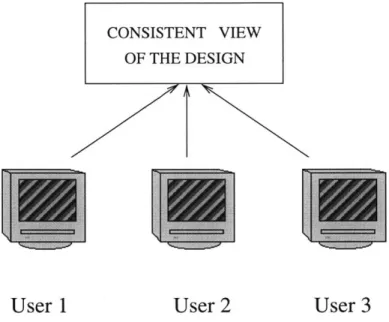
Collaborative design involves various designers co-operating in the design process. The environment used by the designers to access the distributed tools and libraries has to enable collaboration among the designers because of various reasons as mentioned in Section 1.1. The environment should provide an efficient way to exchange the information and allow designers to be involved in parallel sessions at the same time. Though the parallel sessions increase the load on the server, it is sometimes convenient for the designer to participate in more than one session at the same time.
CONSISTENT VIEW
OF THE DESIGN
1'
User 1
User 2
User 3
Figure 1-3: The Concept of the Collaborative Environment
The collaboration should also allow one designer to use the tools and all the designers to view and use the results to enhance the design.
In this model the issues with limited internet bandwidth and secure communications need to be addressed critically. Since, the data has to be transferred to the location where the tool is available, the limitation in bandwidth is of concern. Similarly, the security of communications of the design data over the internet is an important aspect of the design.
The web-tools should have the capability to exchange information efficiently and in a secure manner.
1.6
Related Work
The popularity of the internet and the WWW has lead to many web-based tools. Bentz et al. have proposed an information based design environment[2]. They describe an environment which helps the users to collect and manage information in a uniform fashion, independent of the abstraction levels or implementation platforms. Lidsky and Rabaey present a World Wide Web based prototype tool, PowerPlay[3], which helps in system level exploration of power consumption. PowerPlay uses a HTML form-based user interface which prompts the user to select a subset of the available library and their parameters. The design is then submitted to a script which calculates the power, area and timing information. The methodology combines pre-characterized and user defined modes to provide quick and power estimation in a spread sheet like format at the earliest stages of design, using a distributed
modeling environment.
The WELD project at UC Berkeley
[4],
aims to construct a distributed CAD environ-ment enabling Internet-wide IC design for the US electronic industry. They have developed a Java Object Database Server supporting persistent object class management. Boglilo et al. describe PPP, a gate-level power simulator[5], which provides a Web-based integrated environment for synthesis and simulation of low-power CMOS circuits. The graphical in-terface of PPP is a dynamically generated tree of interactive HTML pages that allow the user to access and execute the tool by using a Web browser.There have been efforts to provide Web-based Interfaces to executable CAD/CAM soft-ware. Links to different Web-based tools can be found at [6]. Fortes et al. present a network based simulation laboratory which can be accessed via standard WWW browser. The Purdue University Network Computing Hub (PUNCH) [7], is a set of network-based laboratories that provide toolkits of programs for various fields.
A stand-alone utility, XMX[8], for sharing an X Window system session on multiple
X displays has been developed at Brown university. It acts as an intermediary between XClient and XServer and takes advantage of the networked nature of the X Window system. Though it leads to a collaborative environment, it works only on X-based systems. It is not
platform-independent and not web-based, the two features that are essential for distributed design. Xplexer[9] is a distributed application sharing system for X Windows. It allows sharing of stand-alone X window applications, in a heterogeneous environment. This tool restricts the applications to those developed in X Windows. Some other such systems that are available include Xshare and XTV. Lavana et al. use executable directed hypergraphs to describe collaborative design activities on the internet[1O].
Although there are numerous instances of design tools being available over the Web, there has been limited attention to design an environment which would allow designers to utilize the different tools over the Web and do design in a collaborative fashion. In this paper we show how a collaborative and distributed environment could be built over the Web, utilizing the core Web technologies, to support efficient communication and data exchange between different Web-based tools and to allow the designers to collaborate in the design.
Chapter 2
Web based Technologies and Java
"Web is a planetary nervous system", - John Barlow, 1996.
There are several technologies, mechanisms and protocols available that support dis-tributed applications with the standard Web interface. In this chapter, we briefly explain some mechanisms that have been used in developing this framework. They include protocols that support the transfer of information through the Web using the HyperText Transfer Protocol, HTTP and those that support remote execution like the Common Gateway Mech-anism, CGI. There are mechanisms that create applications that could be executed locally on the client machines using Java technology, scripts and plug-ins. The mechanisms for communication use object technologies to define, locate and request computational services from participating applications, both remotely and locally. In these approaches, the Web takes the role of providing uniform access and presentation mechanisms. For creators and users of CAD, the Internet is an ideal mechanism for facilitating collaborative design and real time communication.
2.1
The Hypertext Transport Protocol
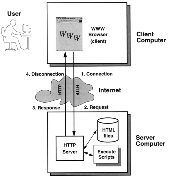
The Hypertext Transport Protocol (HTTP) is the principal means by which a Web server and a client communicate with each other[11]. This communication could be to retrieve a document or to execute a script. Under this protocol, a client sends a request to the server. The server compiles such a request and replies with a response containing the
requested output or with an error message. Together, the request and the response form a
transaction, a single interaction between the server and the client. The protocol is basically
stateless, a transaction consisting of a connection, request, response and a disconnection. A feature of HTTP is the negotiation of data representation, which allows systems to be built independently of the development of new advanced representations.
User
www
7
BrowserClient
(client)Computer
4. Disconnection 1. ConnectionInternet
3. Response 2. Request HTMLfiles
Server
HTTP
Computer
Server LExecute ScriptsFigure 2-1: The components of a simple WWW interaction
There are two common methods or syntax for the request line, GET and POST methods.
GET method is generally used for simple document retrieval, database lookup and similar
of data to the server. The POST method uses the method body to send the additional infor-mation from the user, rather than encoding it in the part of URL as in GET. The client can use different encodings, that the server and the script can understand, for sending the data. The default HTML[12] encoding is application/x-www-f orm-urlencoded which encodes the data as ampersand-limited name/value pairs. The data that needs to be transmitted from the client to the CAD tools in the Web-based CAD paradigm tends to be large and it would be useful to send large files with a single HTML tag. File uploads with the HTML tag <input type=file>, use the encoding of multipart/f orm-data. Error responses are supplied in human readable text in HTML syntax. The error messages and the response messages are different only in the content of the text.
The server breaks the TCP-IP connection when the whole document has been trans-ferred. The client may abort the transfer by breaking the connection before this, in which case, the server does not record any error condition. In the environment of collaborative and distributed CAD, we are dealing with non-deterministic delays, corresponding to the execution time of the tools. The client might have to wait for longer time for some responses in Web-based CAD tools because of these delays. The http server times out after waiting for a specific period of time, which is defined by a server variable. Therefore, the methodology used should be robust with respect to these delays. To allow the users to continue working with the design while waiting for the results from a web-tool, these jobs could be spawned as a thread of execution.
2.2
The Common Gateway Interface (CGI)
Sometimes we need the server to generate information depending on the client input. The Common Gateway Interface[14] is a mechanism to present dynamically generated informa-tion on the World Wide Web. A Hypertext Transport Protocol (HTTP) server is often used as a gateway to a legacy information system: for example, an existing body of documents or an existing database application. The Common Gateway Interface (CGI) is an agree-ment between HTTP server impleagree-mentors about how to integrate such gateway scripts and programs. CGI programs are usually referred to as scripts. They run on the server machine and produce the output (usually HTML output) to be displayed on the client's browser.
running on the server. With CGI, the Web server can execute a program, while passing user specific data to that program. The program processes the data and passes its response back to the server, which sends this data back to the client. CGI transforms the Web from
a simple collection of static hypermedia documents into an interactive medium, in which users can ask questions and execute remote applications.
The request for a CGI program looks the same as it does for all Web documents. The dif-ference is that when a server recognizes that the address being requested is a CGI program, the server does not return the file content, but instead it tries to execute the program.
CGI scripts provide a very useful mechanism to provide remote access to CAD tools. Since many CAD tools take inputs which are either files or some parameters in plain text, HTML forms can easily be used to capture the inputs from a browser interface and can be submitted to CGI scripts. For example, a power estimation tool could have a simple Web interface using the CGI mechanism.
2.3
Java Programming Language
Though the CGI mechanisms allow the client to execute server-side programs, they lack the interactivity and good user interface. Designers would not be satisfied with the limited display of a CGI based program and HTML output. They need to modify and view different designs in real time. Java[13] helps us overcome this problem by allowing us to do complex client-side processing in a platform independent manner.
Java is an object-oriented programming language and comes with a rich set of Applica-tion Programmers Interface (APIs) as shown in Figure 2-2. Java has been widely accepted as the standard for Web computing. Java source code is compiled to byte-codes whose target architecture is the Java Virtual Machine (JVM). This JVM can be embedded within other environments, like the web-browser and operating systems. A class loader can load classes over the network and a byte-code verifier verifies the byte-codes while reading them. Java has been designed such that a compiled Java class can be conveniently handled with ordinary text and graphics. Java applets can be embedded in HTML pages, which are loaded from the Web server. The browser interprets the Java byte-codes and executes them as an application on the client side.
Figure 2-2: Java language and its APIs
than making interactive CGI programs Complex user interfaces where the users use the mouse to draw and edit images, which are not easy to create with HTML and CGI, can be easily incorporated in a Java applet. Java applets use modern graphical user interfaces (GUI) like text boxes, buttons, list boxes etc. With Java, the processing is off-loaded to the user's system and thus Java enables client side processing without the need to go across the network for every small application. Moreover, the problems of the non-persistent connec-tion of HTTP and CGI are alleviated since Java applets run as independent applicaconnec-tions.
The Virtual Machine refers to the active interpreter which executes Java byte-codes. Since the Virtual Machine does not necessarily correspond to any particular hardware or operating system, the Java class files are portable to any implementation of the Virtual Machine. This is the essence of Java's portability. Therefore, applications which do not need extensive computational power could be handled well with Java based interface. But leaving all the work to Java based client-side processing would hinder our attempts to do
CAD with a simple desktop. Therefore what we need is a partitioning of an application
into Java based client processing and the traditional remote server-side computation. Java enables a philosophy of "Write once, Run anywhere" for programs. The features which make Java so attractive are listed below.
e Java is Object-oriented.
" Java is a cross platform language enabling easy portability.
" Java inherently supports multi-threading, enabling a Java Server to time multiplex
several tasks.
" Java has API's for transparent network access and can be inlined in a HTML document
in a Java-capable browser.
To prevent the creation of malicious applets that can damage the file system on the client side, there are some security restrictions on the applets. One of these is that the Java applets are not allowed to examine the file system on the client side. So, the applets can not save designs on the client machines. In a web-based CAD application, the designer, using an applet, might want to save the design on the local machine. This is a limitation on the Java applets that needs to be worked around.
2.3.1 New Features in Javal.1
Several new features have been added in the new version 1.1 of the Java programming language. Out of them, the new event model, the security features, and the serialization mechanisms are extensively used in developing this distributed framework, WebTop into the collaborative environment. The event model is described briefly in this section and the serialization mechanisms are explained in Section2.4.
Event Model:
WebTop was originally developed using Javal.0 event model. In Java 1.0, there are certain Graphical User Interface(GUI) component classes and the applets or the GUIs have to subclass these components and handle events. This model is not suitable for develop-ing complex programs. All these events should be managed in one method action. This necessitates the method to check the cause of the event to take appropriate action.
Javal.1 defines a new model for dispatching and handling events. The new event han-dling model is a "callback" model. When a GUI component is created, the methods that should be invoked on the occurrence of different events, have to be declared. Since Java does
not support first-class functions (functions that can be passed as parameters), an instance of this class has to be passed to the GUI component to specify the callbacks. The GUI component invokes the appropriate method of the object specified. These interfaces are called listeners(e.g., MouseMotionListener, WindowListener). Given below is an example of how this event model has to be programmed with:
" A componentBox has a button. If the user clicks on the button, it disappears and
takes the appropriate action. The componentBox class contains an instance of the Button GUI component.
" The componentBox is added to the button's actionListenerList.
" The componentBox which implements ActionListener interface implements the
ac-tionPerformed method with the signature as specified in the interface.
" When the user clicks on the button, the button component calls the corresponding method in the componentBox class, which takes the necessary action.
In the collaborative environment, where various user actions at the clients are to be broad-cast to all the clients, such a callback model would make the program flow simple. The corresponding message object can be created in this callback method to be sent over the network.
2.4
Distributed Object Technologies
Distributed computing enables the development of applications across several heterogeneous systems. With the growth of the internet and the advances in networking, distributed computing offers a vision of flexible computing with no boundaries. Distributed computing has gained a new direction with a vision of object-oriented computing in which, there is no essential distinction between objects that share an address space and objects that are on two different machines with different architectures and at different geographical locations. Distributed computing in this context refers to programs that make calls to other address space, possibly on other machine. Objects can therefore invoke a method of an object which may be remote to the calling object. In such a system, an object, whether remote or local, is defined in terms of a set of interfaces. The implementation of the object is independent
of the interface and hidden from other objects. This can be seen as an extension to the remote procedure call (RPC) in the object-oriented paradigm.
The distributed programs can communicate through message-passing. These messages are examined by the receiver to take appropriate action on its variables. Java Serialization mechanisms could be used for this purpose to create the messages. In this section we describe in brief the Remote Method Invocation of Java and the Java Serialization mechanisms.
2.4.1 Java RMI
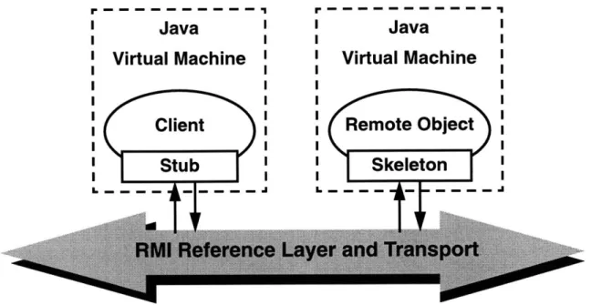
Java Remote Method Invocation (RMI) [16] enables the programmer to create distributed Java-to-Java applications, in which the methods of remote Java objects can be invoked from other Java virtual machines, which might be on different hosts. A Java program can make a call on a remote object once it obtains a reference to that remote object. This reference could be obtained either by looking up the remote object in the bootstrap naming service provided by RMI or by receiving it as an argument or as a return value. A client can make a call on a remote object in a server, and that server can also be a client of other remote objects.
Java Remote Method Invocation (RMI) is an interprocess protocol for Java, allowing Java objects located on different Java Virtual Machines to invoke transparently each others' methods. Since these Virtual Machines could be running on different computers anywhere on the network, RMI enables object-oriented distributed computing.
Java RMI provides the Java programmers with an efficient, transparent communication mechanism that frees them of all the application-level protocols necessary to encode and decode messages for data exchange.
Remote objects written in Java RMI interact in the following way:
" server objects publish their interfaces to make them available to RMI clients.
" stub classes deal with binding to the remote objects and do the client-side data
mar-shaling.
* skeleton classes on the server-side handle incoming calls.
r - -
-Java
I
I
Java
Virtual Machine
' 'Virtual Machine
I~I
III
~I
IIClient
Remote Object
I
~I
IIStub
Skeleton
I
~I
IIFigure 2-3: The Java RMI Mechanism
2.4.2 Java Serialization Mechanisms
Message-passing is another mechanism in which distributed programs could communicate with each other. They could do so by agreeing upon a protocol for communication. Though, RMI does the same thing, a user-defined protocol gives the user more control over the communication. These messages could be implemented as objects using the serialization mechanisms of Java. Programs written in Java could communicate easily in this way.
Object Serialization[17] is the mechanism in Java through which objects are written to output streams. Through deserialization, objects can be read from the input streams at the receiving end. Java writes out the values of all the fields of the object being serialized. If the object refers to another object, serialization is done recursively. Care is taken such that this serialization mechanism does not enter into infinite recursion. Classes should implement
serializable interface for its instantiations to be serializable. The transient and static fields
of an object are not serialized.
The various events at different client ends are to be sent to the server in the collaborative environment and these events are to be broadcast from the server to various clients. The Java Serialization mechanisms are used to create these messages from the Java objects.
2.5
Summary
In this chapter, we presented the enabling technologies for Web-based CAD. HTTP and CGI include protocols and mechanism, which provide access to tools running on the Web server. Java applets can be embedded in Web browsers to enable complex, platform independent client side processing. And finally, the distributed object technologies enable transparent, distributed method invocation on remote objects.
Chapter 3
Design Example with the
Distributed Tool
As a first step in developing the collaborative environment for web-based CAD, a framework for distributed web-based micro-system design, WebTop, was developed[18]. WebTop is an environment in which users can design systems using either the in-built fundamental cells or other designed cells in the library, in a hierarchical fashion. Designer can access the distributed library of cells and can execute several web-based remote tools through WebTop. WebTop can be accessed at the URL http: //apsara.mit.edu/WebTop. An example design using the distributed tool of a single-chip media-processor is described here.
3.1
The Distributed Web-based CAD tool, WebTop
WebTop is a distributed Web-based CAD framework, implemented as a Java applet. It is based on a public domain applet called "Digital Simulator" (DigSim) [191. The entry point of the design is a hierarchical schematic/block editor. This editor has a simple GUI. The design can be validated by using distributed Web-based tools. The netlist of the design can be extracted from WebTop so that it conforms to the input specification of several web-based tools. Such a netlist can be submitted to the remote web-tools.
WebTop includes a hierarchical schematic editor. It includes mechanisms to add and delete cells, to cut and paste schematic, to change properties of cells and the mechanisms to save the designs. WebTop has a number of in-built primitive cells (e.g., logic gates, MOS devices, passive circuit elements). The designer can include them in the design by selecting
them from the menus in the GUI. The properties of these cells(e.g., transistor sizes) can be changed using the pop-up menus. The design can be hierarchical, meaning that a new cell designed can be included within other cells. There is a simple User Interface through which the designer can navigate a cell hierarchically. WebTop supports block editing, in which the user can create a template of the cell and provide a behavioral and structural view in
SPICE or verilog.
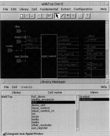
The Library Manager helps the designer keep track of the cells. Figure 3-2 shows a snapshot of the schematic editor and the Library Manager. The designer should be able to save the schematic cells into a file and use it subsequently in the design. This can be performed in two different ways using WebTop. The schematic cells created in WebTop's editor are serializable using the Java serialization mechanisms. So, the cells created by designers can be saved in the Java object format. There is a WebTop file format in which the tool can save the cells in files. The schematic cells saved in both these formats can be loaded into WebTop's editor from the files subsequently. These cells can be downloaded from a URL and so schematic cells created and stored, using WebTop, by another designer can be downloaded and used. WebTop supports distributed cell storage and access. Cells could be stored in different Web servers and such cells can be loaded from WebTop by referring to the corresponding URL. A CellServer exists along with WebTop on the host server and it allows users to store cells remotely at the server's site after checking user authentication. Both the verilog and SPICE views of cells can be entered through a text editor in WebTop. They can also be referred to by a URL or by the location of a local file and WebTop loads them.
The main objective of the distributed environment is to give access to remote Web-tools through a single point web-tool. Therefore, WebTop has a mechanism through which the design(or parts of the design) can be submitted to the web-tools. The designer can extract a netlist from WebTop's schematic, so that it conforms to the Input Specification of the remote tool. The user can also extract the netlist of subparts of the schematic. The user can submit this extracted netlist to the corresponding web-tool through the WWW and obtain the results of its execution. WebTop provides the infrastructure to extract the netlist, to submit it to the web-tool and to get the results back to view them through the browser.
The tool uses the CGI(Common Gateway Interface) mechanisms to invoke remote tools. WebTop has interfaces with several webtools including Pythia [20], a verilog RTL power
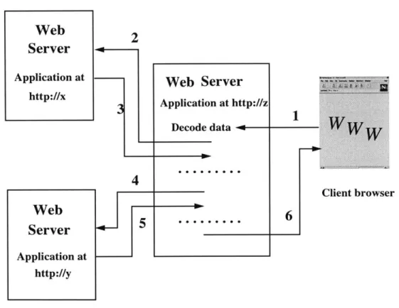
estimator tool, PowerPlay [3], a system level power exploration tool and WebSpice. The extracted netlist is submitted to a CGI script existing on the applet host. The results from the remote tool can be returned to the applet as a dynamic URL, which is used by WebTop to display the HTML page. In some other cases, a Java server is started on the applet host by the CGI tool, which accepts the results from the remote tool through a socket connection. This is also useful when these results should be submitted to a second web-tool, whose output is shown to the designer. Therefore, a new meta web-tool could be created using the CGI mechanisms and the Java server. An example in which a web server at a site z creates a meta webtool, by accessing the tools at the sites x and y, is shown in Figure 3-1 [18].
Figure 3-1: Data flow in Hierarchical tools
Originally, WebTop was developed using Java Development Kit (JDK) Version 1.0. But, as explained in Chapter 2, the event model in JDK Version 1.1 is more suitable for developing the environment into a collaborative framework. So, the whole code base for WebTop was modified to follow the JDK 1.1 format. Also, some useful features like menu
Figure 3-2: A snapshot of WebTop's schematic editor and Library Manager
shortcuts were added to the framework.
3.2
Adding new cells to WebTop
As mentioned in the previous section, WebTop has several inbuilt primitive cells. All these primitive cells have the SPICE and verilog views included in their specification. Each of these cells has a java source file written with these specifications. A primitive cell can be included in the design by selecting the corresponding item from the "Fundamental" menu in the GUI. Designers might need new fundamental cells to simplify the process of design and so WebTop provides the support to add new cells.
One way in which this can be achieved is to create a new blank cell with the required number of ports, both input and output, in it. Such a cell when included in the schematic has a symbolic view which looks like a black box with all these input ports and output
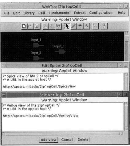
Figure 3-4: A 2 input 1 output prototype cell with Verilog and Spice views
ports. The verilog and SPICE view of this cell could be specified as either separate URLs or as local files. This cell can be used like a primitive cell, by choosing from the library. As an example, in Figure 3-4 a prototype 2 input 1 output cell is shown in the WebTop schematic editor. The Verilog and Spice views are specified as URLs. In Figure 3-5 a cell includes this prototype cell in its schematic.
The other way in which new fundamental cell could be included into WebTop is to include another java source file that follows the format of any of such files (e.g.,AND.java). In this file, the geometry of the view, which the cell should exhibit in the schematic, has
to be specified. The verilog and SPICE views are also to be specified in this file. Any new view(e.g., PowerPlay view) could be defined in this source file. The cell properties are defined in this source file (e.g.,).
3.3
Interaction with tools
As explained in Section1.1, WebTop can interact with several remote web tools. The de-signer can extract the netlist from the design and submit it to a web tool. The tools with which WebTop can currently interact are Pythia, WebSpice, PowerPlay and a DC-DC sim-ulator. Currently, the specifications of extraction of netlist and the manner of interaction with tools is hardwired into the source code and the CGI scripts of the framework.
The first step in making the interaction between a remote webtool and WebTop is to get output from the schematic that conforms to the input specifications(e.g., the input language of that tool). This step would be simpler if the remote tool accepts the WebTop file format as input. Pythia takes the verilog specification of a design along with some technology parameters as input. So, to interact with that tool, WebTop should output verilog specification of the schematic. Each fundamental cell in WebTop has a verilog description of it inlined in its source file. Similarly, a verilog view can be attributed to a cell, as explained in the previous section. The extractor does a hierarchical navigation of the cells to provide the necessary output from the schematic.
WebSpice accepts its input in the SPICE format. In a similar way as explained above, the SPICE views for cells can be specified and WebTop's extractor uses this information to generate the SPICE output.
To incorporate interaction with a new tool, the extraction method in WebTop should have the knowledge of the parts of the schematic that are relevant to the new tool and of the method in which the output for that parts of the design could be generated. New views of the fundamental cells might have to be incorporated in WebTop. For example, the DC-DC simulator only needs the URL of the data input file and so no new information in terms of the views of cells was needed to incorporate interaction with this new tool. In order to make this scalable, all the remote webtools should be using a common format and WebTop should have a netlist extraction capability to that common format.
The netlist extracted from WebTop is submitted to a tool-specific CGI script that is located on the applet host. The tool specific details are all incorporated in these scripts (e.g., the technology parameters in the invocation of Pythia). This CGI script invokes the corresponding webtool. The CGI script on the receiving end of the webtool sends the dynamic URL containing the output or the output itself, back to the invoking CGI script
on the applet host which presents this information to WebTop.
In case of some tools, a JavaServer can be installed on the server, where the tool is lo-cated, to accept the input data and to send the output through socket connections. The CGI scripts and the tool-input-specific view information of WebTop cells are the specifications in WebTop that are to be written for incorporating interaction with a new web-tool.
3.4
Saving the designs
The users should be able to save the schematic designed in WebTop to obtain persistent copies of the designs. This could be done either on the user's local disk or on the applet host. The security restrictions of Java do not allow an applet to read from or write to the local disks. They cannot open a socket connection with any host except the applet host. This problem can be worked around in the following ways:
" A CellServer has been implemented on the applet host site. This is a server program
written in Java, which allows the users of WebTop to store their designs on the applet host after checking user authentication. Since it runs on the applet host itself, the applet can open a socket connection with the CellServer.
" The security restrictions, that are applicable to the downloaded applets, can be set
through the HotJava browser. So, if the browser being used is HotJava, the designs can be saved on local disk by choosing a less strict security mechanism for this applet.
" In JDK1.1, the appletviewer tool accepts digitally signed files. When it loads an
applet that has been signed by a trusted entity, it runs the applet without subjecting to the usual security restrictions. So, digitally signed applets can read and write files on the local disks. Common Web browsers are expected to follow suit and give special privileges to trusted applets. Using these features in the browser, WebTop as an applet can be digitally signed so that the user can save the design on the local machine by trusting this applet.
" If the framework is used as a stand alone application for designing and extracting,
without the interfaces with the distributed tools and libraries, there are no security restrictions and the user can save the designs on local machines.
3.5
Design Example with the Distributed Tool
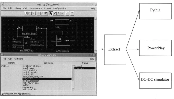
As a driver application, we chose the design of a single-chip media-processor that includes an embedded low-power ARM core, a video compression module, with more than 160,000 transistors in its schematic, and power supply circuits. The design was entered using the WebTop editor and was validated using a distributed simulation strategy. The remote tools used in this process are Pythia, a Verilog RTL power estimator at MIT[20], PowerPlay, a system level power exploration tool[3] at UC Berkeley, and a DC-DC voltage converter simulation tool at Stanford. The netlist is extracted from the circuit to conform to the Basic Input Specification of the remote tools. The different remote tools being used require information about the design at different levels of the design. The method in which the remote tools are invoked varies with the tool being invoked.
Pythia, the tool present at the host at MIT, accepts as input the netlist in Verilog. The verilog netlist of the decompression module is extracted from WebTop and submitted to Pythia to get a power estimate of the module. A CGI call is made by WebTop to the Web Server where Pythia resides. After the CGI script executes Pythia, the dynamic URL containing the results as a HTML file is returned to WebTop which uses the browser's context to display it.
The PowerPlay netlist can be extracted from WebTop and the results of the behavioral level power estimate can be obtaining by executing PowerPlay with this netlist. The CGI tool at MIT is invoked by WebTop when the netlist is submitted to PowerPlay. This tool creates a file with the netlist and returns the URL to WebTop, which contains a link to the CGI script of PowerPlay containing proper links to the design URL. WebTop uses the browser's context to load the page of that URL, which is a HTML spreadsheet of the design generated by the CGI script of PowerPlay. From this spreadsheet all the utilities in PowerPlay can be used. For example, the details in the spreadsheet could be used by PowerPlay to get the behavioral level power estimate.
The mechanism through which the DC-DC simulator is invoked is different from the way in which the other two tools are invoked. The reason is that the results of the simulation from the simulator at Stanford have to be supplied to a graphing utility at MIT and the graph output is to be shown at the client side. Thus, two web-tools are used in the process. This can be viewed as the piping of the processes in UNIX. The simulator code is written
in "C". It has been wrapped up in Java code, which calls the C code as a native method. The sequence of events that occur during the process of getting results from the simulator are given below and are shown in Figure 3-6.
1. The designer extracts the netlist from the schematic in WebTop and submits it to the
simulator.
2. WebTop invokes the CGI script at MIT and passes on the netlist which is saved by the CGI script.
3. The CGI script starts a Java server which sends the netlist to the CGI script at
Stanford as a URL.
4. The CGI script at Stanford starts the Java simulator code, which reads in the data URL and runs the simulation, the results of which are sent back to the Java server at MIT.
5. The Java server at MIT stores the simulation results in a file to be read from by the
graphing utility. It returns a dynamic URL through the CGI script to WebTop. The URL points to the graphing applet to be run with this input file,
6. WebTop uses the browser's context to load the page of that URL to show the resulting
graph.
Steps 2 and 3 above can be combined by making WebTop send the netlist directly to the Java server. But, to maintain the earlier sequence of the applet invoking CGI tool in other tools, steps 2 and 3 are separated.
Thus, using three different remote tools, the design of a single chip media processor has been validated using the distributed environment with the use of a simple web browser. The different ways in which the three web-tools are invoked shows us the flexibility involved and the power of Web-based CAD with respect to the invocation of the tools. Several snapshots of the tool while in the process of executing the design example are shown in Appendix A.
Chapter 4
The Collaborative Environment
WebTop allows a single designer to access distributed libraries and remote web-tools within the framework in the process of the design. It serves as an entry point as well as the center for the design. But, with the increased complexity of the designs diverse expertise is required at various stages of the design. The design teams are typically separated geographically. Thus, there is a need for the distributed framework to be collaborative in nature for it to be more useful.
4.1
CollabTop
The distributed Web-based CAD framework, WebTop, has been extended into a collab-orative and distributed environment, called CollabTop. Conceptually, the collabcollab-orative environment should allow the designers to make changes to the design simultaneously and should show a consistent view of the design to each one of them. This is pictorially shown in Figure 4-1.
First steps in developing such a framework involves deciding a software architecture for the tool and identifying the various changes the designer could do to the design(i.e., the events that a single designer could generate in WebTop). In a typical session with WebTop, the designer creates a schematic by adding new components either from the in-built primitive cells or from the cells in the library. The cell in the library could be the cells
designed by the user previously or those downloaded from distributed cell libraries. The designer can save the cell and proceed to design another cell. Or the designer might choose to extract the netlist from the design to submit to the remote Web-tools. Each of these
CONSISTENT VIEW
OF THE DESIGN
User 1
User 2
User 3
Figure 4-1: Concept of the Collaborative framework
actions of the designer cause the events that are generated through the use of the tool. In order to make the environment collaborative, these events are to be made collabo-rative, i.e., the effect of all the events caused by one designer's actions should be seen by all other designers in their view of the editor. For practical use of the tool, the designers should be able to join other designers in individual sessions and several sessions should be able to run in parallel. This situation is shown in Figure 4-2. The events in one session should not effect the design in other sessions. Hereafter, as we talk about the collaborative environment, we assume that the designers are in the same session, unless specified other-wise. Also, by a user we mean an identity in a session. We can easily imagine the same designer in two parallel sessions at the same time and we consider these two identities as two different users.
4.1.1 Client-Server Architecture
When a designer edits a schematic, several types of events are generated. These events have
to be propagated to all other designers so that they could take the corresponding action on their design. These events can be either propagated to all other designers or can be sent to a central server which broadcasts these events to all the other designers. These are the peer-to-peer and the client-server models respectively. The client-server model is used
User 1
User 2
User 3
User 4
Figure 4-2: Collaborative design with several sessions
in CollabTop. The events that are generated by any client are sent to the central server which is responsible for the broadcast of these events to all the clients. The most important reason for choosing the client-server model is that it is easier to incorporate the higher level ideas, as explained in the next section( e.g., synchronization into the system), in this model. Another reason is that the number of channels involved in a client-server model is smaller than the peer-to-peer model and so it is less error prone to the network congestion due to other traffic. If n is the number of designer clients in a session, the number of channels needed by a client-server model is of the order O(n) whereas the number of channels needed
by a peer-to-peer network is O(n2). Moreover, a client-server system can be scaled later in
order to support multicasting in the connections from the server to the clients.
There is a provision to enter the session in a read-only mode. Clients with read-only capabilities can view the actions of other designers in the session (e.g., the selection of a cell). But, the client cannot cause any actions in the session. This feature is particularly useful in the design reviews. Events produced by such a client are not broadcast to the clients in the collaborative environment, but the client would be able to see the consistent view of the copy being edited. Some clients can highlight parts of the cell and edit the cell, and the read-only client can view it. It is very useful in the design review phase, where particular parts of the design can be highlighted and hierarchically edited by one or more
Session 1
Design of Adder
Session 2
Design of ALU
CLIENT-SERVER Architecture
PEER-PEER Architecture
Figure 4-3: Client-Server and Peer-to-Peer Architecture
clients and the read-only client would be able to view it.
It is desirable to have designers across sessions to communicate with each other. In Java, an event is generated when a menu selection occurs. But, the client who did not generate the event does not know which menu item selection generated that event, because examining the menuitems does not generate any event in Java. When a designer selects a cell from a menu of the tool, the event of the menu popping up and the selection of a menu item is not visible to other designers as these actions do not generate any events in Java. Only after a menu item is selected, Java generates an event. A chat tool has been implemented to come into use in such situations. It follows the client-server architecture too and the designers across sessions share this tool. A ChatServer is also run along with CollabServer, the server for the collaborative events.
4.2
Higher Level Issues
For the framework described in the above sections to work, some higher level software design issues must be addressed. This includes the protocol of message passing, the issues of reliability of clients and recovery of the tool from the sudden death of any of the clients. The issues like reordering of messages and locking of some critical resources have to be taken into account.