Publisher’s version / Version de l'éditeur:
Vous avez des questions? Nous pouvons vous aider. Pour communiquer directement avec un auteur, consultez la première page de la revue dans laquelle son article a été publié afin de trouver ses coordonnées. Si vous n’arrivez pas à les repérer, communiquez avec nous à [email protected].
Questions? Contact the NRC Publications Archive team at
[email protected]. If you wish to email the authors directly, please see the first page of the publication for their contact information.
https://publications-cnrc.canada.ca/fra/droits
L’accès à ce site Web et l’utilisation de son contenu sont assujettis aux conditions présentées dans le site
LISEZ CES CONDITIONS ATTENTIVEMENT AVANT D’UTILISER CE SITE WEB.
Paper (National Research Council of Canada. Division of Building Research); no.
DBR-P-1070, 1982
READ THESE TERMS AND CONDITIONS CAREFULLY BEFORE USING THIS WEBSITE. https://nrc-publications.canada.ca/eng/copyright
NRC Publications Archive Record / Notice des Archives des publications du CNRC : https://nrc-publications.canada.ca/eng/view/object/?id=ed9a64cd-6c0a-47fe-86d8-75fb90d40afe https://publications-cnrc.canada.ca/fra/voir/objet/?id=ed9a64cd-6c0a-47fe-86d8-75fb90d40afe
NRC Publications Archive
Archives des publications du CNRC
This publication could be one of several versions: author’s original, accepted manuscript or the publisher’s version. / La version de cette publication peut être l’une des suivantes : la version prépublication de l’auteur, la version acceptée du manuscrit ou la version de l’éditeur.
For the publisher’s version, please access the DOI link below./ Pour consulter la version de l’éditeur, utilisez le lien DOI ci-dessous.
https://doi.org/10.4224/40001701
Access and use of this website and the material on it are subject to the Terms and Conditions set forth at
Normalized heat load: a key parameter in fire safety design
Harmathy, T. Z.; Mehaffey, J. R.
National Research
Conseil national
1
Council Canada
de recherches Canada
NORMALIZED HEAT LOAD: A KEY PARAMETER
INFIRE SAFETY DESIGN
by T.Z. Harmathy and J.R. Mehaffey
Reprinted from
Fire and Materials
Vol. 6 No. 1,1982
p. 27
-
31
DBR Paper No. 1070
Division of Building Research
SOMMAIRE
On montre que l a charge combustible e s t un paramstre u t i l e pour c l a s s i f i e r d i f f s r e n t s feux s e l o n une h c h e l l e d e g r a v i t 6 ( d e s t r u c t i o n s p o s s i b l e s ) . Ce paramstre peut S t r e c o n v e r t i en r e s i s t a n c e au feu (paramstre u s u e l ) .
Normalized Heat Load: A Key Parameter in
Fire Safety Design
T. Z. Harmathy and J. R. Mehaffey
Division of Building Research, National Research Council of Canada, Ottawa K I A OR6, Canada
It is demonstrated that the normalized heat load is a suitable parameter for ranking various enclosure fires on a 'potential for destruction' scale. This parameter is convertiile to the familiar fire resistance.
INTRODUCTION total heat absorbed by a unit surface area of the
enclosure during. the fire incident. He went on to The way fire resistance tests are conducted has a great
deal to do with the tendency to regard the temperature history of an enclosure fire as the primary descriptor of its severity. The temperature of an enclosure fire or, more exactly, the average temperature of the fire gases in the enclosure is usually looked upon as the embodi- ment of the destructive potential of the fire, and the boundaries of the enclosure as passive participants in the fire process that merely respond to the destructive conditions imposed upon them. The temperature his- tory of fire gases is, according to the traditional con- cept, the fundamental information through which the potentials for destruction of enclosure fires can be compared, and the parameter used directly in the comparison is, as a rule, taken as the time integral of the temperature-time curve above some arbitrarily selected level.
This concevt of enclosure fires can be obiected to on
prove that heat-load is a measure of the maximum temperature that some key load-bearing element of the enclosure boundaries will attain as a result of fire exposure and thereby a measure of the destructive potential of fire.
Although heat load is an apt descriptor of the relative severity of fires in a given enclosure, it is not a parameter that can be used to compare the destructive potential of fires occurring in unlike enclosures. Take, for example, two fires, one in enclosure A, which is lined with fairly good conductors (i.e. with materials of
high thermal inertia), and the other in enclosure B,
lined with insulators (i.e. materials of low thermal inertia). Assume that the heat load on the boundaries of both enclosures is the same. Clearly, it takes two fires of different severities to drive the same amount of heat (per unit surface area) into the boundaries of enclosures A and B.
two grounds. ' ~ i r s t , it is inaccurate to kquate the
characteristics of an enclosure fire with those of the NORMALIZED HEAT LOAD
gases in the enclosure; the nature of a fire is, in fact, the result of a strong and complex interaction between fire gases and the enclosure. Second, since the heat transfer from the gases to the enclosure boundaries (which evidently has something to do with the destruc- tive potential of a fire) is mainly by radiative energy exchange that depends on the fourth power of the temperature of fire gases, a simple time integral of the temperature has no relevance to the integrated effect of the gases on the enclosure boundaries.
HEAT LOAD
Harmathy has pointed out1 that by virtue of the interaction between the fire gases and the enclosure it is permissible and perhaps more convenient to ex- amine a fire through its effect on the enclosure bound- aries. He introduced a variable referred to as 'heat load' and defined it as
r 7
(where q is heat flux penetrating the enclosure bound-
aries, t is time and T the duration of the fire) i.e. as the
The problem of how to compare fires in unlike enclos- ures has essentially been solved by the introduction of the concept of 'normalized heat load'.' The nor- malized heat load, H, is defined as*
where
GC
is the thermal inertia of the enclosureboundaries, k the thermal conductivity, p the density
and c the specific heat. In other words H is the heat
load referred to the thermal inertia of the enclosure. It must be pointed out that, since heat load does not depend linearly on the thermal inertia of the enclos- ure, normalization does not result, as one might ex- pect, in elimination of the effect of the thermal prop- erties of the enclosure from the expression of heat load. The benefit of normalizing the heat load is (as will be proved later) that a parameter is obtained which is capable of ranking all kinds of building fires from the point of view of their potential for destruc- tion.
Naturally, until such a proof is provided, one is entitled to think of the normalized heat load only in
@ Wiley Heyden Ltd, 1982 FIRE AND MATERIALS, VOL. 6, NO. 1, 1982 27
T. Z. HARMATHY AND J. R. MEHAFFEY
the literal sense, as a modified quantifier of the total heat absorption during a fire incident. If, as usual, the various boundary elements of an enclosure are built from different materials,
6
in Eqn (1) should be interpreted as the overall thermal inertia representing the weighted average of the thermal inertias for the individual boundary elements:where
and the subscripts i relate to information pertinent to the i-th boundary element of the enclosure and A stands for the boundary surface area (in total, or with subscript i, i-th component).
For a given enclosure fire the normalized values of the heat load are approximately equal for all boundary elements of the e n c l o s ~ r e , ~ irrespective of their ther- mal inertias and are, in addition, equal to the nor- malized heat load applicable to the enclosure as a whole. This has been referred to as the 'theorem of uniformity of normalized heat load'. It is expressed by the following equation:
where q, is the heat flux penetrating the i-th boundary element.
To eliminate possible misunderstanding it should be pointed out that the theorem is concerned with the distribution of heat load among the boundary surfaces of an enclosure involved in fire. According to the theorem, the normalized heat load is insensitive to the thermal inertias of the individual boundary elements of the enclosure. This claim is by no means in conflict with the earlier statement that the normalized heat load is sensitive to the (overall) thermal inertia of the
enclosure as a whole.
An example has been worked out to illustrate the point. It relates to an enclosure with a surface area of
112.2 m2 and a window of 2.8 m2. The fire load is cellulosic, 858 kg, and corresponds to a specific fire load of 30 kgmp2 (referred to the floor area). Three cases are considered: in the first the enclosure is lined with normal weight concrete, in the second with light- weight concrete and in the third the walls are lined with lightweight concrete and the floor and ceiling with normal weight concrete. The applicable values of thermal inertia are given in the second column of Table 1. For the third case the value shown was calculated from Eqn (2). The normalized heat loads
As standard fire resistance tests are, in a sense, also enclosure fires, all statements made so far are applica- ble to them as well. A convenient feature of standard test fires is that, unlike real-world enclosure fires, they have a unique temperature history. One may assume, therefore, that the normalized heat load for standard test fires is a function only of the duration of the test. Detailed analysis has revealed2 that this assumption is more or less correct, provided that the tests are per- formed in 'ideal' high-efficiency furnaces, i.e. in fur- naces heated by 'black' combustion gases. If the tests are carried out in real-world test furnaces, the nor- malized heat load will also depend on such secondary factors as the size of the furnace, its lining materials, the nature of the combustion products of the fuel and the test specimen.
As discussed in Ref. 2, for any furnace that is very nearly ideal the heat load on the test specimen and the walls of the furnace can be calculated as though they were heated individually by radiation from a black body whose temperature is programmed to follow the temperature-time curve prescribed by the standard. (The reason why neglecting the convective contribu- tion to the heat transmission is permissible was also discussed.')
Table 1. An example to show that the normalized heat load is higher if an enclosure is lined with better insulat- ing materials
H T
Lining material (J m - 2 s ~ ' 1 2 K ( S " ~ K ) (h)
are listed in the third column. These values have been obtained by using the calculation technique described in Ref. 3. (The values in the last column of the table will be discussed later.)
The tabulation shows that the normalized heat load assumes higher values if the enclosure is lined with better insulating materials. The theorem of uniformity of normalized heat load means that in the third case the normalized heat load is approximately the same for the walls (lined with lightweight concrete) as for the floor and ceiling (lined with normal weight con- crete) and equal to the value applicable to the com- partment as a whole, i.e., equal to 3.72 x
lo4
s1I2 K.STANDARD FIRE RESISTANCE TEST
0 0 . 5 I . 0 1 9 2.0 2.5
2192
Normal weight concrete 2.89 x lo4 0.68
LENGTH O F E X P O S U R E i O S T A N D A R D F l R E T E S T , ~ ( h ) Lightweight concrete 931 5.O7x1O4 1.26
Normal weight and Figure 1. The H versus T relation for high-efficiency fire test
lightweight concretes 1534 3.72 x lo4 0.90 furnaces (numbers on curves refer to lining materials listed in Table 2).
NORMALIZED HEATLOAD: A KEY PARAMETER IN FIRE SAFETY DESIGN
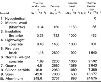
Table 2. Typical values of the thermal properties of materi- als used in the illustration (for appropriate temper- ature intervals)
Thermal Specific Thermal conductivity Density heat inertia
k 0 c
JG
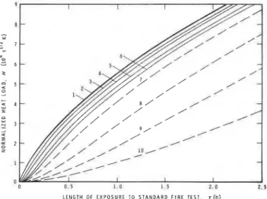
Material (W m-' K-') (kg m-3) (J kg-' K-') (J m-' s-'I2 K-') 1. Hypothetical 2. Mineral wool (fiberfrax) 3. Insulating fire brick 4. Lightweight concrete 5. Fire clay brick 6. Normal weight concrete 7. Quartz 8. Silicon carbide 9. Steel 10. AluminumThe calculation procedure is described in the Appen- dix. The results of the calculations, related to ten materials, are illustrated in Fig. 1 in the form of H versus T plots, where T now means the duration of the test fire. The thermal properties of the ten materials are listed in Table 2. One is a hypothetical material with zero thermal inertia, three (mineral wool, insulat- ing fire brick and fire clay brick) are common furnace- lining materials, two (lightweight concrete and normal weight concrete) are common compartment-lining ma- terials, two (steel and aluminum) are structural materi- als, and two (quartz and silicon carbide) are materials selected to fill the gap between insulators and conduc- tors.
If the theorem of uniformity of normalized heat load were strictly correct, a single H versus T curve would have resulted for all ten materials. Clearly, this
was not the case. Yet, if only the common
compartment- and furnace-lining materials are consi- dered, i.e. those usually referred to as insulators, the discrepancies do not appear to be unduly large. Those who are ready to strike a balance between mathemati-
" 0 0 . 5 1 . 0 1 . 5 2 . 0 2 . 5 L E N G T H O F E X P O S U R E T O S T A N D A R D T E S T F I R E . r (h) Figure 2. Unified correlations between H and T for standard
fire tests; (1) for a black-gas furnace; (2) for the floor test furnace in the DBRINRC laboratory (estimated).
cal rigour and engineering pragmatism will probably admit that for all practical cases the theorem of unifor- mity of normalized heat load is an acceptable approxi- mation.
It is a sound engineering principle that whenever a concept is not valid in the strictest sense it should be put into practice in such a way as to err on the safe side. It has been recommended2 that in designing for fire safety the curve in Fig. 1 pertaining to normal weight concrete (a compartment-lining material with the highest thermal inertia among common building materials) be regarded as a unique representation of the relation between normalized heat load and fire test duration. That curve is reproduced separately as curve 1 in Fig. 2. For real-world test furnaces the H versus T curve will follow a flatter course. Curve 2 in the same figure relates to the floor test furnace at the National Research Council of Canada. With the procedure out- lined in Ref. 2, similar and possibly not very different curves could be derived for furnaces in other laboratories.
POTENTIAL FOR DESTRUCTION SCALE As the heat load has been proved a valid measure of the destructive potential of fires,' the logical proce- dure in establishing whether the boundary elements of an enclosure are capable of withstanding a real-world fire is to subject specimens of all those elements in standard test fires to the same heat loads as their counterparts are expected to endure in the real-world fire. If the specimens perform satisfactorily during the tests, the lengths of the tests will be assigned to the constructions they represent as their 'fire resistance' ratings and these ratings will determine the position of the individual constructions along a 'resistance to de- struction by fire' scale.
The practical procedure is as follows:
(i) Calculate (e.g. in a way described in Ref. 3 or Ref. 4) the normalized heat load on the enclosure. (By virtue of the theorem of uniformity of normalized heat load, this same value is applicable to all individual boundary elements of the enclosure.)
(ii) Enter this value of H along the ordinate axis of the H versus T plot in Fig. 2 and read the correspond- ing value of T, i.e. the required length of exposure to standard fire test, along the abscissa axis. (The values listed in the last column of Table 1 were arrived at in this way, using curve 2 of Fig. 2 as the applicable curve .)
From the fact that the normalized heat load on the enclosure is used to determine how long (specimens of) all boundary elements of the enclosure should be exposed to standard test fires in order to ascertain their 'resistance to destruction by fire', it follows that the normalized heat load itself is the measure of the 'potential of fire for destruction' for the real-world enclosure fire. Furthermore, from the fact that for standard test fires H is an increasing monotonic func- tion of T, it follows that the normalized heat load scale is a unique scale of the 'potential for destruction' for
-
T. Z. HARMATHY AND J. R. MEHAFFEY
real-world fires. It must be emphasized that the valid- demonstrated that the normalized heat load (i.e., the
ity of this statement does not depend on the specific heat absorbed by a unit area of the boundaries of an
way the value of the normalized heat load is assessed. enclosure or by its components, referred to the applic-
A note of caution should be added, however. The able value of thermal inertia) is a parameter suitable
concept of normalized heat load to correlate a real- for ranking various enclosure fires from the point of
world fire with a test fire is obviously of limited view of their potential for destruction. This ranking is
applicability whenever the construction material ex- compatible with that along a 'resistance to destruction
posed to either fire does not retain its integrity. by fire' scale.
CONCLUSION Acknowledgement
This paper is a contribution from the Division of Building Research
The fallacies involved in characterizing real-world fires of the National Research council of canada, and is published with
by their temperature histories are pointed out. It is the approval of the Director of the Division.
REFERENCES
1. T. Z. Harmathy, Fire Mater. 4, 71 (1980). 5. H. S. Carlsaw and J. C. Jaeger, Conduction of Heat in Solids, 2. T. Z. Harmathy, Fire Mater. 5, 112 (1981). 2nd Edn, p. 76. Oxford University Press, Oxford (1959). 3. T. Z. Harmathy, Fire severity: basis of fire safety design.
Presented at International Symposium on Fire Safety of Concrete Structures, ACI Convention, San Juan, Puerto Rico. 21-26 September (1980).
4. J. R. Mehaffey and T. 2. Harmathy, Fire Technol. 17 221
(1981). Received 21 August 1981
APPENDIX
Because the conditions on the reverse side of a fire veloped by Carslaw and Jaeger,' namely
test specimen do not, as a rule, affect the rate of heat
absorption on its obverse side for a period longer than Ts(t) = T,(O)
+
-It
q(t - 0 ) ( ~ 0 ) - ~ ~ " d0 (7)the duration of fire test, it is permissible in studying the heat load on the specimen to regard the specimen
6 0
(where 0 is a dummy time variable) has been con- as a semi-infinite solid. If the test is performed in a
high-efficiency furnace, the heat transmission to the verted into the following form2
specimen can be modelled as transmission by radiation
Ts(j) = ~ ~ ( 0 ) +
&
q ( j - m + l )from a black body whose temperature is programmed T ,,,=I (8)
to follow the standard temperature versus time curve.
The ASTM E 119 curve can be approximated by the to suit the numerical technique to be followed. In Eqn
following analytical expression: (8) m = 1 , 2 , ... j.
Finally, by virtue of Eqn (I), the normalized heat load
Tf(j) = T,(O)
+
a(1- Cba)+
c a t (5) for the duration of a test fire, T = nAt, is obtained aswhere, in preparation for a finite difference calculation A t
technique, the time t, is written in the form jAt; At is a H(n) =
-
J k p C i = li
q(j)(9)
pre-selected time increment, j = 0 , 1 , 2 , 3 ,
...,
and, withany function, f(j) means f(t) at t = jAt. T, is the temp- As Eqn (1) shows, knowing the q(t) (or q(j)) func-
erature of the 'furnace7 (hypothetical black body tion is a prerequisite to ascertaining the ~ ( r ) (or
temperature), and a, b, and c are constants, a = 750 K, H(n)) function, the relation between the normalized
b = 0.063 26 s-'l2, c = 2.8402 s-lI2 K. heat load and the duration of fire test. The calculation
According to the outlined heat transmission model, of q(t) consists of a repeated application of ~ q n s ( 5 ) ,
the heat flux that penetrates the surface of the test (61, and (8). After defining the values of Tf(O), Ts(0)
specimen, q (slightly adjusted to suit the calculation and q(O) (usually Tf(O)= Ts(0) =293.2, and naturally
technique) is q(0) =O), T,(l), q(l), and Ts(l) are calculated in first
round, then T,(2), q(2), and T,(2) in the second round
4(j) = ~ d [ T , ( j ) ] ~ - [T,(j - 1>14} (6) and so on.
Before proceeding with the calculations, a choice of
where T, is the temperature of the surface of the the time increment, At, has to be made. Usually a
specimen, u is the Stefan-Boltzmann constant, and & tentative value is assigned to A t and the possibility of
is the emissivity of the specimen, usually taken as 0.9. achieving stable solutions (obtaining a smooth sequ-
TO obtain an expression for T,, an equation de- ence of values for q for the time interval desired) is
30 FIRE AND MATERIALS, VOL. 6, NO. 1, 1982
NORMALIZED HEATLOAD: A KEY PARAMETER IN FIRE SAFETY DESIGN
examined. It is clear from Eqn (8) that the smaller the value of the thermal inertia, the smaller also the value At that may offer stability. If stability is assured, further calculations are conducted with steadily de- creasing values of At to test the convergence of the solutions. Experience showed that for values of K p c about 100 J m-2 s - " ~ K-' the value of A t may be as low as 0.1 s to secure reasonably accurate solution.
An examination of Eqn (8) will reveal that in cal- culating T,(n all values of q(,, are needed for the interval 1 s m 5 j. Thus, if it is necessa to select a
small value for A t (which is the case if
&
pc is small), the storage and manipulation of all these values (amounting possibly to 100 000 or more) becomes prohibitively expensive. Fortunately, as Fig. 1 shows, the H(T) curves run quite close for small values ofJk@,
and apparently converge to an H(T) curve rep- resenting a hypothetical material with *= 0. For this limiting case the calculations can be performed by a much more convenient technique.Since Eqn (7) is a convolution in time, it seems expedient to use the technique of Laplace transforms. The Laplace transforms for the surface temperature of the specimen and for the rate of heat absorption are as follows:
and
where p is a dummy frequency and ATs is surface temperature above the initial level.
In a rearranged form, the Laplace transform for Eqn (7) is
It is clear, however, that as Jk@+O, Ts+ T,, irrespective of the heat transfer mechanism. Conse- quently
where again ATf stands for the temperature of the 'furnace' above its initial level. If one now takes the Laplace transform for T,, as given by Eqn (5) (remembering that jAt = t), substitutes it into Eqn (13), and inverts the resulting Laplace transform, one obtains an expression for lim (q(t)/cpc) for
JkW4
0. Substituting this expression in Eqn (1) and performing the integration, one finally arrives at the following expression:(lim H(T))G+o =
a g
This is the expression used in calculating the H(T) relation for the limiting case c p c + 0, which is also illustrated in Fig. 1.
I
NOMENCLATURE
boundary surface area (m2) specific heat (J kg-' K-') normalized heat load (s1I2 K) thermal conductivity (W m-' K-') 0 , 1 , 2 , 3
,....
= 1 , 2 , 3 , . . . j = 1 , 2 , 3 , .
. .
dummy frequency in Laplace transform (s-') heat flux (W mP2)
time (s)
time increment (s)
'furnace' temperature (K) \
'furnace' temperature above initial level, (K) surface temperature (K)
surface temperature above initial level (K)
Greek Symbols
E emissivity of specimen surface, dimensionless
0 dummy variable (s) p density (kg mY3)
a Stefan-Boltzmann constant, 5.67 x lo-', (W mP2 K-3
T duration of fully developed period of fire; dura-
tion of fire test (s) Subscript
i pertaining to the area or material of the i-th boundary
Other symbols
Laplace transform of q
This publication is being distributed by the Division of Building R e s e a r c h of the National R e s e a r c h Couricil of Canada. I t shouldnot be reproduced in whole o r in p a r t without p e r m i s s i o n of the original publisher. The Di- vision would b e glad to be of a s s i s t a n c e i n obtaining such p e r m i s s i o n .
Publications of the Division m a y be obtained by m a i l - ing the a p p r o p r i a t e r e m i t t a n c e ( a Bank, Expreas, o r P o s t Office Money O r d e r , o r a cheque, m a d e payable to t h e R e c e i v e r G e n e r a l of Canada, c r e d i t NRC) t o t h e National R e s e a r c h Council of Canada, Ottawa. K1A OR6. Stamps a r e not acceptable.
A l i s t of a l l publications of the Division i s available and m a y be obtained f r o m the Publications Section, Division of Building R e s e a r c h , National R e s e a r c h Council of Canada. Ottawa. KIA OR 6.