HAL Id: hal-00944397
https://hal-enac.archives-ouvertes.fr/hal-00944397
Submitted on 1 Jul 2014
HAL is a multi-disciplinary open access
archive for the deposit and dissemination of
sci-entific research documents, whether they are
pub-lished or not. The documents may come from
teaching and research institutions in France or
abroad, or from public or private research centers.
L’archive ouverte pluridisciplinaire HAL, est
destinée au dépôt et à la diffusion de documents
scientifiques de niveau recherche, publiés ou non,
émanant des établissements d’enseignement et de
recherche français ou étrangers, des laboratoires
publics ou privés.
Investigation of CSK as a Candidate for Future GNSS
Signals
Axel Javier Garcia Peña, Philippe Paimblanc, Daniel Salós, Olivier Julien,
Marie-Laure Boucheret, Thomas Grelier, Lionel Ries
To cite this version:
Axel Javier Garcia Peña, Philippe Paimblanc, Daniel Salós, Olivier Julien, Marie-Laure Boucheret,
et al.. Investigation of CSK as a Candidate for Future GNSS Signals. EWGNSS 2013, 6th European
Workshop on GNSS Signals and Signal Processing, Dec 2013, Munich, Germany. �hal-00944397�
Investigation of CSK as a Candidate for Future GNSS
Signals
Axel Garcia-Pena, Daniel Salos, Olivier Julien
SIGNAV Research GroupENAC Toulouse, France, garcia-pena@recherche.enac.fr, salos@recherche.enac.fr, ojulien@recherche.enac.fr
Marie-Laure Boucheret
INPT-ENSEEIHT/IRIT University of Toulouse Toulouse, France Marie-Laure.Boucheret@enseeiht.frPhillipe Paimblanc
TéSA Toulouse, France philippe.paimblanc@tesa.prd.frThomas Grelier, Lionel Ries
Radionavigation Signals and EquipmentsCNES Toulouse, France
roudier@recherche.enac.fr, Thomas.Grelier@cnes.fr, Lionel.Ries@cnes.fr
Abstract— This paper presents an analysis on the
implementation on a GNSS signal of a Code Shift Keying (CSK) modulation: an orthogonal M-ary modulation specifically designed to increase the bandwidth efficiency of direct-sequence spread spectrum (DS-SS) signals. Two decoding methods are presented as suitable candidates to be implemented by a CSK modulation with a LDPC channel code: classical sequential decoding and Bit-interleaved coded Modulation – Iterative Decoding (BICM-ID).
Afterwards, this paper presents the methodology used to construct CSK signals which increase the useful bit rate with respect to a BPSK signal but maintaining the same symbol rate. This methodology includes the calculation and comparison of signal demodulation performances in AWGN and mobile channels, the generation of CSK symbols allowing the desired bit rate and the determination of the codeword durations. Proposals for real signals have been made.
Finally, this paper analyses the impact of processing a CSK modulated signal on a GNSS receiver with respect to a BPSK signal. This analysis includes the increase of complexity of the demodulator block and the possible performance degradation of the acquisition and, the carrier and code delay tracking.
Keywords— GNSS; demodulation performance; Clock and Ephemeris Data; channel model; Land Mobile Satellite; statistical propagation model; narrowband propagation; urban
I. INTRODUCTION
GNSS signals are designed to provide the receiver with precise synchronization or pseudo-range measurements and to broadcast limit amount of essential information (satellites ephemeris, clock error correction, etc.). The combination of these two elements allows a GNSS system to provide the user with its PVT (position, velocity, time) [1][2].
The historical design choice for the GNSS system synchronization part consisted in implementing direct sequence-spread spectrum (DS-SS) characterized by a very narrow autocorrelation function. The historical design choice of the GNSS signal communication part consisted in the implementation of a BPSK modulation (a BOC modulation is a BPSK modulation from the demodulation point of view) [3]. This choice was made in order to allow the easy implementation of the DS-SS synchronization part. Moreover, at the epoch, the low bandwidth efficiency of a BPSK modulation (number of bits/second/Hz) [3] did not present any limitation to the signal design due to the low required bit rate.
Nowadays the unique hybrid GNSS signal structure can be rethought due to the introduction of a new dataless (pilot) channel on the future GNSS signals: possibility to generate the pseudo-range measurements from the pilot channel. Therefore, the data channel is no longer necessarily restricted by the GNSS system special hybrid characteristics [2]. One example is the LEX signal of the Japanese QZSS system [4]. Another example could be the GPS L1C signal: 75% power allocation to the pilot channel [5] could lead to receivers discarding the data channel for synchronization purpose.
Moreover, the extension of the GNSS user community with high expectations in terms of new services (precise positioning, safety-of-life, etc.) and positioning capabilities in more challenging environments demand a higher data rate (currently obtained via other systems [6][7]). Therefore, the low bandwidth efficiency of a BPSK modulation is becoming an important limitation.
The main constraint of using a BPSK data modulation to increase the signal data rate is the GNSS signal design choice of employing direct sequences (necessary for precise pseudo-range measurements). The PRN code is thus limited by the data symbol duration which must decrease in order to increase the
data rate and thus either the chipping rate or the PRN code should also be modified.
In this paper, the modulation known as Code Shift Keying (CSK) [8][9][10][11], specially designed to increase the transmission rate of a spread spectrum signal [8], is inspected.
In this paper, first, the CSK modulation and its fundamentals are defined. Second, the advantages and disadvantages of using a CSK modulation on a GNSS signals are presented. Third, the decoding methods proposed for a CSK modulation implementing a binary LDPC channel code are described. Fourth, the objectives and the methodology used to design a CSK signal are given. Fifth, real numeric propositions of CSK signals are made. Sixth, the impact of a CSK modulated signal on a GNSS receiver is analyzed. Seventh, the conclusions are given.
II. CODE SHIFT KEYING MODULATION TECHNIQUE
A. CSK Definition
The CSK modulation technique is a DS–SS signaling method which overcomes the spreading gain versus data rate limitations [8].
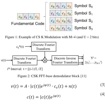
The CSK is a form of orthogonal M-ary signaling over a communication channel [9] since M orthogonal signaling waveforms are used in order to transmit U = log2(M) bits. The special characteristic of the CSK modulation with respect to the typical orthogonal M-ary signaling is that each waveform (or symbol representing a set of input bits) is obtained from a different circular cyclic phase shift of a single fundamental PRN sequence. Moreover each circular cyclic phase shift is made by an integer number of chips [8] and is assumed to be a full period version of the fundamental sequence [10]. Figure 1 provides a graphical explanation of the CSK modulation. B. CSK Modulation Mathematical Model
Each single CSK symbol modulates U bits. The number of circularly shifted versions of the fundamental code is equal to M, where M = 2U. The CSK fundamental code is called cd(t) and has a period length equal to which spans over C chips. C is not necessarily equal to M and the chip interval is equal to Tc. From this fundamental code cd(t), the modulator generates the M circularly shifted versions, which are called c0(t) to cM-1(t). A mathematical expression of a generic circularly shifted version of the code is shown below:
[ ] (1)
[ ] [ ] (2) Where mx is the integer number representing the code shift of the xth symbol and mod(x,y) represents the modulus operation of y over x.
C. CSK Modulated signal at the RF block output
The equivalent low-pass received signal at the receiver RF block output, v(t), can be modeled when assuming the transmission of a CSK signal through a non-frequency selective channel [3] as:
Figure 1: Example of CS K Modulation with M=4 (and U = 2 bits)
Figure 2: CSK FFT-base demodulator block [11]
| | (3)
| | (4)
Where A is the received signal amplitude, is the received signal complex envelope (modeling the influence of the propagation channel), is the instantaneous received signal carrier phase introduced by the propagation channel,
| | is the module of the received signal complex envelope,
and n(t) is the equivalent low-pass AWG noise with power equal to σ2.
D. CSK Correlator Output Mathematical Model
In order to estimate which CSK symbol is transmitted by the data component, a matched filter (equivalent to a correlator) should be implemented for each component (symbol) of the signal space basis [3]. For a CSK modulation, since each symbol is a circular shifted version of the fundamental code, each matched filter output is equivalent to the evaluation of the correlation between the received signal and the fundamental spreading sequence at a different shift, the bank of matched filters can be replaced by Fourier Transform and Inverse Fourier Transform blocks which conduct the correlation in the frequency domain [11]. Figure 2 shows the CSK FT-based bank of correlators block scheme and equation (5) shows the conducted mathematical operation:
( [ ] [ ] ) (5) The mathematical model of the normalized bank of correlators output for the I component at the ith interval (or instant), YI,i vector, can be modeled as:
{
(6) ∫ | | ( ) (7)
̂ (8)
Where, ̂ is the estimated signal carrier phase and is the PRN code length. Expression (6) is modeled assuming that the code delay is perfectly estimated. Moreover, expression (6)
also assumes that the correlation between two shifted versions of the fundamental PRN code can be neglected. For this same reason, the noises are assumed to be independent. Therefore, are independent narrow-band Gaussian noises with power equal to , and, is the CSK symbol rate ( ).
For a coherent demodulation process, the application of a CSK FT-based bank of correlators for the I component suffices to demodulate the data as explained in the next section. However, for a non-coherent demodulation process, the received must also apply a CSK FT-based bank of correlators to the Q component.
The mathematical model of the normalized bank of correlators output for the Q component at the ith interval (or instant), YQ,i vector, can be modeled as:
{
(9) ∫ | | ( ) (10) E. CSK Coherent Demodulator Output Mathematical Model
The coherent demodulation of process of a CSK modulated signal consists in recovering the entire power carried by the data component in the I component of the receiver.
The recovery is made by estimating with a high accuracy the received signal carrier phase, ̂ [3]. This means that expression (7) and (10) become:
∫ | | (11)
(12)
Therefore, it can be observed that all the useful power is contained on the I component. Finally, since a coherent demodulation process requires a very accurate estimation of the received signal carrier phase, this method is adapted to AWGN channels where the received signal carrier phase remains constant (or have a linear evolution easily estimated).
F. CSK bits likelihood ratios mathematical expression for coherent demodulation
The general expression of the likelihood ratio of the uth bit of an orthogonal CSK modulation at the ith interval for a coherent demodulation process is [12]:
∑ ( ) ∑ ( ) (13) Where, ∑
represents the addition of all the
elements , evaluated by function , which represent a combination of bits where the uth bit is equal to b at the ith instant ( = b). ( ) is the a-priori probability of :
( ) ∏ ( )
(14)
Where, is the value of the zth bit, bz, of the k
th
CSK symbol at the ith instant.
Equation (13) shows that depending on the a-priori probability of the different correlator outputs , the likelihood ratio of the bits vary. In fact, depending on this probability, more weigh is given to certain correlator outputs and thus, if this a-priori probability is reliable, the likelihood ratio expression should also be more reliable in average. This means that a way to improve the demodulation/decoding performance of a CSK signal consists in determining reliable symbol a-priori probabilities.
G. CSK Non-Coherent Demodulator Output Mathematical Model
The non-coherent demodulation process of a CSK modulated signal consists in recovering the entire power transmitted by the data component from a non-linear combination of the I and Q components of the received signal.
More specifically, for a non-coherent demodulation process, the received carrier phase is usually not estimated,
̂ . But instead, each component of the vector (I component) is individually squared and added to the corresponding squared component of the vector (Q component). Afterwards, a square-root is applied to each individual result. Therefore, the entire data component power is recovered:
| | √( ) ( ) (15) The non-coherent demodulation process becomes an attractive method to be used when the estimation of the received signal carrier phase is hard to achieve, with a desired level of accuracy, due to its fast evolution in time. The scenarios which present this kind of received signal carrier phase variation are mobile channels (modelling urban or indoor environments).
Note that for an AWGN channel, the non-coherent demodulation is not interesting because the received signal carrier phase is easily estimated and because the C/N0 value of
| | is lower than the C/N0 value of for an accurate
estimation of the received signal carrier phase.
H. CSK bits likelihood ratios mathematical expression for non-coherent demodulation
The general expression of the likelihood ratio of the uth bit of an orthogonal CSK modulation at the ith interval for a non-coherent demodulation process is:
∑ | | ( ) ∑ | | ( ) (16)
Where represent the modified Bessel Function of the first kind and order 0.
Figure 3: Codeword source mapping A (above) and codeword source mapping B (below) of a CSK modulation
From expressions (13) and (16), it can be seen that the bits likelihood expressions for a non-coherent demodulation process are the same as for a coherent demodulation process: the only difference is the exponential function which is replaced by the Bessel function.
Nevertheless, expression (16) is not optimal for any kind of propagation channel. In fact, only for channels having a constant carrier phase (or a constant carrier phase estimation error, , after correction by the estimated carrier phase) along the PRN code length and channels whose expressions (7) and (10) can be approximated as shown in expressions (17) and (18), expression (16) is optimal. For the other type of channels, this expression is suboptimal: the optimal expression is very difficult to determine since it depends on the received signal complex envelope (phase and module) distribution.
(17)
(18)
I. Codeword Source Mapping
The codeword source mapping of an orthogonal M-ary modulation is defined as the mapping between the bits carried by an orthogonal M-ary symbol and the bits belonging to a codeword. The codeword source mapping is a very important element of an orthogonal M-ary modulation since it determines the codeword duration and the signal demodulation performance. In this paper, two types of mappings are analyzed since they represent the most extreme cases. Both mappings are represented in Figure 3.
Mapping A: Each bit mapped by an orthogonal M-ary
symbol belongs to a different codeword. Mapping A was shown to provide the best demodulation/decoding performance in [12] but requires more time to access the codeword.
Mapping B: All the bits mapped by an orthogonal M-ary
symbol belong to the same codeword. It provides the worst demodulation / decoding performance [12] but the fastest access to the codeword
III. ADVANTAGES AND DRAWBACKS OF A CSK
MODULATION WITH RESPECT TO A BPSK MODULATION
A. Advantages
The first and most important advantage is the possibility of implementing a non-coherent demodulation since a CSK modulation is a kind of orthogonal M-ary modulation [3][8]. Therefore, a non-coherent modulation may enable CSK signal demodulation in harsh environments (such as mobile channels representing urban or indoor environments) whereas for a BPSK signal the demodulation would not be possible unless the PLL has achieved lock.
The second advantage is that the symbol rate, chipping rate and PRN code length of a reference signal must not be modified when the original coded bit rate is increased: the coded bit rate increase is simply achieved by introducing a CSK modulation in the reference signal (instead of a BPSK modulation) or by increasing the number of bits mapped by a CSK symbol (within a limit). In fact, for a BPSK signal, in order to increase the coded bit rate, the symbol rate must also increase. This modification leads to two possible scenarios: either the PRN code length can remain constant but the chip rate and thus the signal bandwidth is increased, or the PRN code length can be decreased but there is a degradation of the PRN code performance: isolation and near/far effect [27].
The third most important advantage is the flexibility of the coded bit data rate provided by a CSK modulation: the coded bit data rate of a CSK modulated signal can dynamically change at any moment of the signal transmission in order to be adapted to the kind of broadcasted data and its priorities [27]. Moreover, the coded bit rate dynamic change can follow a predetermined structure or could even be changed on-the-fly. The coded bit rate of a BPSK modulation is constant.
B. Drawbacks
The main drawback of a CSK modulated signal is that the synchronization process is extremely hard to achieve: due to each different PRN code cyclic shifted version found in each received symbol, the receiver cannot know which cyclic shifted local replica must be generated in order to synchronize the signal. This means the receiver would need first to demodulate the CSK signal. But the demodulation process is not possible without first acquiring the signal and tracking the code delay. Therefore, from the previous explained reasons, a CSK modulated signal needs a pilot signal in order to achieve the synchronization required to demodulate (either coherently or non-coherently) the signal and to provide the essential pseudo-range measurements.
The second drawback is the increase of the receiver complexity, more specifically the demodulator part: the introduction of a CSK modulation implies that instead of only using one correlator which output is fed to the decoder/detector block, M correlators are necessary (with the consequent complexity increase).
Figure 4: BICM-ID scheme
Nevertheless, the introduction of a FFT-based demodulator for a CSK signal reduces the complexity (and number of operations) of the receiver as shown later in section VII.C. However, a FFT-based signal presents some problems which must be further analyzed.
IV. DECODING METHODS
In this section, two decoding methods for a CSK modulated signal when implementing a binary LDPC channel code are described. The decoding method plays a very important role on the final signal structure design since it determines the demodulation performance and the receiver’s complexity.
The chosen binary LDPC channel code is the GPS L1C subframe 2 LDPC (1200, 600) [5]. The decoding methods are: the Classical CSK Decoding method and the Bit-Interleaved Coded Modulation – Iterative Decoding (BICM-IT) [27].
Moreover, there is no difference between the decoding methods applied to the output of a coherent demodulation process and the decoding methods applied to the output of a non-coherent demodulation process. In fact, the only difference between a coherent and non-coherent demodulation plus decoding process is the input (bits likelihood expression) provided by the demodulation processes.
A. Classical CSK Decoding Method (CD)
The classical CSK decoding method of the jth codeword is simply the traditional sequential decoding method used in [12]: first the bits Likelihood Ratio (LR) or Log LR of the transmitted bits of the jth codeword are calculated and second, the jth codeword is decoded using the previous calculated LR values:
1) Apply equation (13) or (16) in order to calculate the LR of the bits transmitted in each CSK symbol. The symbols a-priori probabilities are assumed equiprobable.
2) Gather the LR values of all the bits belonging to the jth codeword.
3) Decode the jth codeword using the LR values.
4) If there still are LR values belonging to other un-decoded codewords, go to step 2 in order to decode them. In Mapping A, steps 2 to 4 are repeated as many times as bits mapped by a CSK symbol.
B. Bit-Interleaved Coded Modulation – Iterative Decoding (BICM-ID)
The original BICM method was discovered by [14], which give its name, and the complete iterative method, BICM-ID, was conceived by [15]. Moreover, this method was proposed for orthogonal M-ary modulations and non-coherent
demodulation in several papers [16][17][18].
The fundamental idea consists in iterating/mixing the decoding of the parallel codewords transported by a CSK modulation with the calculation of the LR of the CSK symbols bits. More in detail, the iterative decoding method consist in first using the extrinsic information provided by the decoding of the parallel codewords transported by the CSK symbols as a-priori bit probabilities on the calculation of the CSK symbols bits LR. Second, the new bits LR are used as new inputs to the channel code decoder of the transported codewords.
The BICM-ID algorithm is presented next:
1) Calculate the bits LR of all the bits constituting the codewords transmitted in parallel using equation (13) or (16), and using the CSK symbol a-priori probabilities (equiprobable for the first iteration).
2) Use the bits LR calculated in step 1) as inputs to the codewords decoding algorithms and execute the process (totally or partially).
3) Inspect if all the codewords are correctly decoded. i. Yes The iterative process is ended
ii. No Use the bit probabilities obtained in step 2) from the decoding process execution in order to calculate the CSK symbol a-priori probabilities using equation (14). Go to step 1).
V. CSKSIGNAL DESIGN
In this section, the methodology used for designing a CSK modulated signal which increases a predefined useful bit rate with respect to a reference BPSK signal but keeping the same symbol duration (or rate) is presented.
The design of a signal consists in determining the signal parameters in order to fulfill certain objectives or requirements. The CSK signal parameters are the number of bits mapped by a CSK symbol, the number of consecutive PRN codes constituting a CSK symbol, the pair channel code – decoding method and the codeword duration.
Moreover, these parameters also determine the signal BER and WER, and thus they have to be dimensioned in order to target a BER of 10-5. The desired BER can be targeted in open environments (AWGN channels) and in urban environments (mobile channel). Therefore, in this section the two channel mathematical models used to model the targeted environments are also presented.
A. Reference BPSK signal
The chosen reference signal is based on the GPS L1C signal since this signal implements the most powerful channel
code among all the defined GNSS signals at the study’s epoch.
The selected channel code is thus the LDPC (1200,600) of subframe 2. The application of this channel code generates codewords with a duration of 1200 symbols (1200∙Ts).
Figure 5: CSK symbol with respect to a BPSK symbol when keeping the coded bit data rate
B. CSK signal design Methodology
First, the increase of the useful bit rate is obtained by simply applying the CSK modulation instead of the BPSK modulation and thus, the useful bit rate is increased by a U factor.
Second, although one of the signal hypotheses is to keep the original signal symbol duration, a CSK symbol can be artificially extended by coherently accumulating N consecutive identical circular shifted PRN codes. In fact, the original signal parameters which should remain constant in order to maintain the original signal spectrum and original inter and intra interference characteristics are the chipping rate and the PRN code length. Therefore, there is no impediment to coherently accumulate N PRN codes to construct a new symbol with a larger duration, (see equation (19)).
(19)
The new signal bit rate is thus equal to:
(20) And this means that whereas for a BPSK signal the accumulation process results into a decrease of the bit rate, for a CSK modulation the final bit rate is still increased if N < U. From now on, in this paper, the choice of the U and N parameters is called the CSK configuration of a CSK signal. Moreover, this paper calls equivalent the CSK configurations which provide the same bit rate but using different U and N values (U/N = U’/N’).
Figure 5 presents an example of two equivalent CSK configurations which increase the original BPSK signal bit rate by a factor of 3. The first configuration consist in simply changing the original BPSK symbol by an 8-ary CSK symbol (U=3 bits, N=1, for 3 bits/symbol), whereas the second one consist in accumulating 2 consecutive identically shifted PRN codes which represent a 64-ary CSK symbol (U=6 bits, N=2, for 3 bits/symbol).
Third, the comparison among the demodulation performance of different decoding methods is made by comparing the BER vs normalized C/N0 ( | . The C/N0 is
not used since it is preferred to express the final demodulation performance independently from the symbol rate (easier to generalize the results to any PRN code period). Moreover, the Eb/N0 cannot be used since the comparison is also made
between different useful bit rates and the term which is originally fixed is the Es/N0. However, due to the possibility of
artificially extending the CSK symbol, the Es/N0 varies among
different CSK configurations. Therefore, this paper has decided to express the demodulation from an artificial figure of merit which is simply the C/N0 normalized by the rate of the original
BPSK symbol (or PRN code).
| (21)
| (22)
Finally, the normalized C/N0 required for an artificially
extended CSK symbol can be calculated from the normalized C/N0 of the original CSK symbol:
| | (23) Where | is the normalized C/N0 associated to a
signal with a factor of increased data rate of x.
However, for a mobile channel, the PRN code length also modifies the impact of the channel on the bank of correlators output, YI,i and YQ,i. therefore, the comparison will be made using the C/N0 figure of merit.
Fourth, the duration of the new codewords of the CSK modulated signal with increased useful bit rate, , are:
(24) Where n is the number of bits constituting the codeword, the number of bits mapped by a CSK symbol which belong to the same codeword, S (S=1 for mapping A and S=U for mapping B) and the PRN code length, .
C. AWGN channel model
In the case the signal is propagated through an AWGN channel, the coherent demodulation process is assumed to be selected and a high accurate received signal carrier phase estimation is also assumed to be achieved. Therefore, since for an AWGN channel the amplitude is constant and equal to 1 (for the selected noise power ), expressions (7) and (10) become:
(25)
(26)
D. Land Mobile Satellite channel model
In the case the signal is propagated through a Land Mobile Satellite (LMS) channel, the non-coherent demodulation process is assumed to be selected.
In this paper, we assume that the LMS propagation channel is non-frequency selective. This means that the received signal can be modeled as presented in equation (3), where the received signal complex envelope represents the influence of the channel on the received signal. This also means that the modeling of the signal transmission through a LMS channel is completely achieved by the correct modeling of the coefficient c(t) (received signal complex envelope). The generation of
presented next and depends on the selected narrowband mathematical channel model. The Perez-Fontan channel model is selected in this paper [29].
The Perez-Fontan channel model characterizes the [ ] values with a Loo distribution, as described in [29] and [30]. In fact, the received signal is composed of two components: the direct path and the multipath. The direct path is described by a lognormal distribution of mean (in dB with regards to the unblocked Line-Of-Sight or LOS) and standard deviation (also in dB), while the multipath component is described by a Rayleigh distribution characterized by the multipath average power (in dB with regard to the unblocked LOS). The sum of these two components can be directly modelled by the Loo probability density function:
√ ∫ [ ] ( )
The relation between , , and , , is [29]:
, √ , and
.
The value of the Loo parameters is not constant but evolves in time in order to take into account the motion of the scenario conditions. In fact, the Perez-Fontan channel model is a 3-state model, where each state corresponds to a certain level of shadowing/blockage of the direct signal component (LOS Conditions, Moderate Shadowing, Deep Shadowing). Therefore, the Loo parameter values will depend on the channel state.
However, this aspect of the model, which corresponds to very slow variations of the shadowing/blocking conditions of the direct signal, is not taken into account: the simulation results are provided for each shadowing / blockage condition, or in other words, for each state. Therefore, shadowing / blockage parameters are fixed for each simulation case, or in other words, for each selected state. Consequently, the effects taken into account by the channel model of the received signal are only slow variations (non-uniformity of obstacles) and fast variations (multipath).
The direct use of the expression of the Loo distribution to generate samples is not numerically stable and does not account for signal phase. Therefore, it is usually preferred to rely on the implementation proposed in [30] and illustrated in Figure 6.
The numerical details of the sample generation used for the simulations are the following:
The speed of the mobile is 50km/h.
The filter used to model Doppler Spread is a second
order Butterworth filter.
The statistical parameters used for the present study
correspond to the LOS conditions state: ,
, and .
Figure 6: Generation of the [ ] coefficient following a Loo distribution with Butterworth multipath [Burzigotti, 2008]
The [ ] values are generated with a sampling period of 0.1ms, then accumulated over where is the PRN code length (assumed to be 4ms) and N is the number of consecutive PRN codes constituting a CSK symbol. Therefore, the expressions (7) and (10) become:
∑| [ ]| [ ] (27) ∑| [ ]| [ ] (28) (29)
E. Methodolay application and results
The demodulation performance (BER vs norm C/N0) of a
CSK signal implementing a LDPC (1200, 600) channel code, using the classical decoding method (CD) for mapping A, and using coherent demodulation in an AWGN channel is presented in Figure 7. In this figure, different CSK configurations (U and N pair of values) are used in order to attain an increase of twice the original bit rate. From Figure 7, it can be seen that configurations with larger U and N values outperform configurations with smaller values. However, the receiver complexity increases along with U.
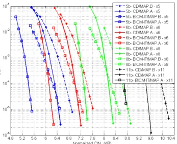
The demodulation performance (BER vs norm C/N0) of
different CSK signals with increased bit rate with respect to a reference BPSK signal, and when using coherent demodulation in an AWGN channel, is presented in Figure 8. These CSK signals implement a LDPC (1200, 600) channel code and use the CD method and the BICM-IT method for mappings A and B. The CSK configurations (U, N) implemented for these CSK signals always have a coherent accumulation number of PRN codes equal to 1 (U, N=1). From Figure 8, it can be concluded that BICM-IT outperforms Classical Decoding and mapping A outperforms mapping B.
The demodulation performance (BER vs C/N0) of a CSK
signal implementing a LDPC (1200, 600) channel code, using the CD and BICM-IT methods for mapping A, and using non-coherent demodulation in a mobile channel, is presented in Figure 9. In this figure, two CSK configurations are used in order to attain an increase of twice the original bit rate: (U=3 and N=1) and (U=6 and N=2).
Figure 7: BER vs norm C/N0 for a different (U,N) configuration of a CSK
signal using CD with mapping A when increasing the bit rate by a factor of 2 w/r to a BPSK signal. Coherent demodulation in AWGN channel.
Figure 8: BER vs normalized C/N0 for CSK signals with increased bit rate
with respect to a BPSK signal. CSK signal use Classical Decoding method (CD) and Bit-Interleaved Coded Modulation - Iterative Decoding (BICM-IT) with mapping A and mapping B. All the CSK configurations are defined (U,
N=1). Coherent demodulation in AWGN channel.
Figure 9: BER vs norm C/N0 for a different (U,N) configuration of a CSK
signal using CD method, BICM-ID method and with mapping A when increasing the bit rate by a factor of 3 w/r to a BPSK signal. Coherent demodulation in AWGN and non-coherent demodulation in mobile channel.
TABLE I. CODEWORD DURATION OF A CSK SIGNAL IMPLEMENTING A
LDPC(1200,600) CHANNEL CODE WHEN INCREASING THE USEFUL BIT RATE OF A REFERENCE BPSK SIGNAL BY A FACTOR OF U/N.
Mapping B Mapping A Bits per CSK symbol, U 4 300∙N∙Ts 1200∙N∙Ts 5 240∙N∙Ts 6 200∙N∙Ts 8 150∙N∙Ts 11 ≈110∙N∙Ts 12 100∙N∙Ts
From Figure 9, it can also be seen that configurations with larger U and N values outperform configurations with smaller values. However, for a mobile channel the demodulation performance gain of the BICM-IT method with respect to the CD method is lower than for an AWGN channel. Moreover, as was expected, the demodulation performance is better for a AWGN channel using coherent demodulation than for a mobile channel using non-coherent demodulation.
Table I shows the codeword duration of a CSK signal implementing the LDPC(1200,600) channel code and increasing the useful bit rate of the reference BPSK signal by a factor of U/N. The codeword duration is given as a function of the number of bits mapped by a CSK symbol, U, the number of PRN codes coherently accumulated, N, and the implemented mapping. From Table I, it can be observed that mapping A has longer codewords than mapping B. Moreover, it can be observed that although using CSK configurations with high U and N values provide better demodulation performance (regardless of the implemented mapping), when using mapping A these configurations have longer codewords than equivalent CSK configurations with lower U and N values. Therefore, a trade-off between demodulation performance and codeword duration / receiver complexity is found when using mapping A. However, when using mapping B, the codewords have exactly the same duration when using equivalent CSK configurations. Therefore, the previous trade-off is limited between the demodulation performance and the receiver complexity.
VI. PROPOSED CSK-BASED SIGNALS FOR GNSS In order to design a signal that is realistically usable for GNSS users, it was decided to take into account a certain number of constraints specific to the GNSS field. These general constraints were derived from the principal conditions of reception and the analysis of the current and future GPS and GALILEO signals:
The maximum number of bits mapped by a CSK symbol
is set to 13 bits ( since the maximum length GNSS PRN code length is 10230 for GPS L1C [5].
A received C/N0 between 15 and 45 dB-Hz [1]: This
constraints provides the maximum and the minimum C/N0 which a signal can expect to find.
A limited time to access the codeword in order to reduce the Time-To-First-Fix (TTFF). The TTFF conditions the choice of the maximum codeword duration.TABLE II. SIGNAL CHARACTERISTICS AND CONSTRAINTS FOR A CSK
SIGNAL INCREASING THE USEFUL BIT RATE OF A REFERENCE BPSK SIGNAL BUT KEEPING THE SAME SYMBOL RATE.
PRN Symb. Period 1ms to 10ms
Useful Bit rate 250bps to 5kbps
Codeword max. Duration 10s
Codeword number of bits 600 Invariant bits ≥ 600 variant bits
Mapping LDPC (1200,600) Mapping B Mapping A
TABLE III. CONSIDERED PRNCODE DURATIONS ASSUMING THAT SEVERAL IDENTICAL SHIFTED PRN CODES CAN BE REPEATED TO CREATE A
CSK SYMBOL
Reference BPSK Symbol
Rate
PRN Code Duration Ref. BPSK CSK with Increased 1 ms 1ms 1 to 5ms (max = 5 ms)
4 ms 1 to 4ms 1 to 24ms (max = 24ms)
10 ms 1 to 10ms 1 to 20ms (max = 20ms)
TABLE IV. NUMBER OF MULTIPLICATIONS FOR CSKDEMODULATION FOR THE TRANSMISSION OF U BITS PER CSK SYMBOL WHEN N=1PRN CODES ARE COHERENTLY ACCUMULATED.NUMBER OF MULTIPLICATIONS FOR BPSK
MODULATION WHEN U BITS ARE SEQUENTIALLY DEMODULATED.
Number of Multiplications CSK BPSK PRN Code Length U Radix-2 Traditional IFFT Bank of Traditional Correlation Correlator 1023 6 11264 71680 65472 6138 8 11264 268288 261888 8184 10230 6 245760 1179648 654720 61380 8 245760 4325376 2618880 81840 10 245760 16908288 10475520 102300 12 245760 67239936 41902080 2004600
A. Specific signal characteristics and constraints
Table II summarizes the signal characteristics and constraints of a CSK signal increasing the useful bit rate of a reference BPSK signal but keeping the same symbol rate. Two types of codewords which divide the proposition of the new CSK modulated in two are defined:
a) Codeword of 600 invariant bits: Around 600 bits are necessary to carry the satellites ephemeris and clock error correction [21]. Code source mapping B is proposed since its coherent accumulation is easier to achieve than for mapping A.
b) Codewords of 600 or more variant bits: Information of new applications of services. Mapping A is proposed. B. Propositions in an AWGN channel
Table VII shows the CSK signal design parameters when the codewords carry 600 in variant bits and when the codewords carry 600 or more variant bits.
Table VII must be interpreted as the choice made by the
authors’ paper as the most suitable CSK signal design
parameters for each one of the analyzed cases in an AWGN
channel with coherent demodulation. Nevertheless, the reader could design a CSK signal with other parameters which better suits its signal needs.
VII. IMPACT OF A CSK MODULATION ON A GNSS RECEIVER
A. CSK signal model
The proposed CSK signal is assumed to have 2 components: a data component only carrying CSK symbols and a pilot component necessary to synchronize the signal.
The pilot component has a primary PRN code of the same length as the CSK symbols PRN code. Moreover, both PRN codes are synchronized in order to facilitate the synchronization and demodulation of the data component from the pilot component. Additionally, the pilot component should incorporate a secondary code synchronized with the codewords of the data component (as GPS L1C [5]).
Table III shows the different PRN codes periods depending on the proposed CSK signal option. It was assumed that the duration of a PRN code would not be greater than 24ms, which is close to the maximum usual values for a GNSS signal (between 1 and 10 ms). Different allocations of power between the data and pilot component are analyzed: Data 25% - Pilot 75%, Data 50% - Pilot 50% and Data 75% - Pilot 25%.
B. Reference BPSK signal model
The reference BPSK signal model used to compare the impact of a CSK modulated signal on a GNSS receiver with a BPSK modulated signal have two components, a BPSK modulated data component and pilot component.
For both components of the BPSK signal, the implemented PRN code has the same length and chipping rate as the components of the CSK modulated signal. For the data component, the only difference is obviously the implemented modulation.
C. Impact of CSK on the Receiver Architecture
The increase of the receiver’s complexity when using a
CSK modulated signal is found on the demodulator block which is more complex than the demodulator of a BPSK signal. In this section, the increase of complexity is shown by means of presenting the number of multiplications which should be conducted in a CSK demodulator in comparison to a BPSK demodulator.
Two types of demodulators are proposed for a CSK modulated signal, the bank of matched filters (or correlators) and the FFT-based correlator. Moreover, there are two algorithms which can be implemented to apply the FFT-based correlator: the traditional IFT and FT calculation method or the radix-2 Cooley-Tukey FFT algorithm [22].
Table IV shows the number of multiplications required for the different types of CSK demodulators when a CSK mapping U bits and spanning N=1 identical PRN codes is transmitted. Moreover, in order to allow for a fair comparison with a BPSK signal, the number of multiplications required for the traditional BPSK demodulator is shown when U bits are sequentially demodulated. From Table IV, two conclusions can be extracted. First, for the two values of PRN codes length
being analyzed (1023 and 10230), the radix-2 Cooley-Tukey FFT algorithm demodulator always requires the smaller number of multiplications to demodulate a CSK symbol. However, even this modulator requires a larger number of multiplications than the typical BPSK demodulator. Besides, the difference in number of multiplications between the Radix-2 CSK demodulator and the BPSK demodulator is increased when identical PRN codes are coherently accumulated (N > 1). Finally, when considering using the FFT-based correlator, one has to keep in mind that it creates constraints on the sampling frequency. Indeed, once the receiver is synchronized with the incoming signal, it is important that all the correlator outputs are synchronized with actual PRN code shifts. This means that the samples of the correlation function fall exactly on multiples of a chip. This means that the sampling frequency needs to be a multiple of the chipping rate, which is known to be non-optimal for synchronization purpose [23], especially when the Doppler frequency is close to 0 Hz. For reducing the computational burden, the same constraint actually applies to traditional correlation computation since typical hardware receiver generate local replicas of the PRN code based on shifts that are multiples of the sampling time. However, it seems easier to release this constraint on hardware receiver using traditional correlators than for hardware receiver using FFT-based correlators.
D. Impact of CSK on Acquisition
In this subsection, a comparison between the joint data/pilot acquisition method (only applicable to BPSK signals) and the pilot-only acquisition method (applicable to both modulations) is made in order to inspect the degradation on the acquisition sensitivity introduced by a CSK modulation. Both methods have the same frequency and code delay uncertainty [2], and use the same acquisition detector: the standard single dwell acquisition technique described in [24].
Table V shows the signal characteristics and acquisition parameters of this analysis. Table VI and Table VII show the acquisition threshold (total signal C/N0) for the joint data/pilot
acquisition method and for the pilot-only acquisition method with different data/pilot power share. From these tables, it can be see that the pilot-only acquisition method needs to have 75% of the power allocated to the pilot component in order to have the same acquisition performance as the joint data/pilot acquisition method. If only 50% of the power is allocated, there is a degradation of acquisition sensitivity of 2 dB.
Therefore, it can be concluded that for acquisition purposes, the BPSK data demodulation seems more appropriate as it enables the possibility of a joint data/pilot acquisition. However, in case a 75%/25% pilot/data power split is used, BPSK and CSK signals would have similar performances. E. Impact of CSK on carrier phase tracking
For the carrier phase tracking process, the main difference between the joint pilot/data carrier phase tracking method and the pilot-only carrier phase method is the type of discriminators of the PLL which can be implemented [2]. In fact, the implemented discriminators for a pilot component have a wider linear region than the implemented discriminators for a data component.
TABLE V. ACQUISITION THRESHOLDS (TOTAL DATA+PILOT C/N0 OF
THE SIGNAL) FOR DIFFERENT DATA/PILOT POWER SHARE,COHERENT
INTEGRATION TIME AND NON-COHERENT SUMMATIONS FOR A TARGETED
FALSE ALARM PROBABILITY EQUAL TO THE INVERSE OF THE PRNLENGTH
(1023CHIPS) AND A TARGETED DETECTION PROBABILITY OF 90%
Coherent Integration time (ms) Dwell Time on 1 acquisition bin (ms) Acquisition Technique (dB-Hz) Pilot- or Data-only with 75% Pilot- or Data-only with 50% Data+Pilot 1 10 34.65 36.4 34.4 50 30.25 32 30.2 100 28.45 30.2 28.5 5 10 32.75 34.5 32.2 50 27.65 29.4 27.5 100 25.75 27.5 25.6 10 10 32.05 33.8 31.5 50 26.75 28.5 26.4 100 24.65 26.4 24.4
TABLE VI. ACQUISITION THRESHOLDS (TOTAL DATA+PILOT C/N0 OF
THE SIGNAL) FOR DIFFERENT DATA/PILOT POWER SHARE,COHERENT
INTEGRATION TIME AND NON-COHERENT SUMMATIONS FOR A TARGETED
FALSE ALARM PROBABILITY EQUAL TO THE INVERSE OF THE PRNLENGTH
(10230CHIPS) AND A TARGETED DETECTION PROBABILITY OF 90%
Coherent Integration time (ms) Dwell Time on 1 acquisition bin (ms) Acquisition Technique (dB-Hz) Pilot- or Data-only with 75% Pilot- or Data-only with 50% Data+Pilot 1 10 35.25 37 35.2 50 30.95 32.7 30.9 100 29.15 30.9 29.1 5 10 33.65 35.4 33.1 50 28.45 30.2 28.2 100 26.45 28.2 26.3 10 10 33.05 34.8 32.4 50 27.65 29.4 27.2 100 25.45 27.2 25.2
Therefore, [25] show that although the joint data/pilot method can use all the available signal power [25] and for the only method the data component power is lost, the pilot-only method provides better carrier phase tracking performance in poor environments. Therefore, it can be concluded that there is no degradation of carrier phase tracking performance between a CSK signal and a BPSK signal since the BPSK will probably track the signal carrier phase using a pilot-only method.
Finally, CSK modulation allows a non-coherent demodulation whereas a BPSK demodulation does not.
F. Impact of CSK on code delay tracking
As opposite to a joint pilot/data carrier phase tracking method, a joint pilot/data code delay tracking method can implement the same discriminators on the data component as on the pilot component. The reason is that the mostly used discriminators are non-coherent, thus removing the data [25].
However, the use of the same discriminator on both components implies that the correlator outputs of the data and pilot components have to be output at the same time, and thus that the coherent correlation duration is the same on both components. Therefore, although the discriminators are non-coherent, the coherent integration must still be restricted over a data symbol.
Moreover, the code delay tracking process admits longer coherent integration than the carrier phase tracking process. And it is well known that long coherent integrations improve the code tracking jitter, filter more slowly varying multipath and interference and potentially enables the use of the secondary code properties [25].
Therefore, although a joint/data code delay tracking method can use the same discriminator for both components and can use the entire signal power, an only-pilot code delay tracking method will provide better performance [25] since it could implement longer coherent integrations.
VIII. CONCLUSIONS
This paper has clearly highlighted the CSK modulation advantages: non-coherent demodulation, possibility to increase the bit rate without modifying the symbol rate, chip rate or PRN codes properties and the flexibility of dynamically changing the signal bit rate. Moreover, the drawbacks have been identified: the necessity of introducing a pilot channel to synchronize the signal and the increase of the complexity of the receiver demodulator block.
Afterwards, this paper has presented two decoding methods for a CSK signal implementing a binary LDPC channel code and has proposed two demodulation methods: coherent demodulation process and non-coherent demodulation process. The decoding methods have been evaluated with a proposed methodology for designing CSK modulated signals which pursue to increase the useful bit rate with respect to a reference BPSK signal while keeping the same symbol rate. Moreover, the demodulation performance of the transmission of a CSK signal through an AWGN channel and a mobile channel has been analyzed and the bits likelihood ratios expression for a non-coherent demodulation process has been presented. This paper has shown the trade-off between demodulation performance, receiver complexity and codeword duration of the decoding methods and codeword source mappings.
Finally, the analysis of the impact of a CSK modulated signal on a GNSS receiver has shown that although a FFT-based demodulator (radix-2) reduces the complexity of the receiver, this kind of receiver raises an issue with the required sampling frequency.
Moreover, this paper has shown that there is no acquisition performance degradation if at least 75% of the power is allocated to the pilot channel, and that there should not be carrier or code delay tracking performance degradation since pilot-only tracking methods outperform joint pilot/data methods.
IX. FUTURE WORK
On-going work is centered on consolidating the demodulation performance of a CSK signal in an urban environment (mobile channel) for a coherent demodulation process and for a non-coherent demodulation process. Besides, future work will analyze the limitations on the number of bits mapped by a CSK symbol, U, of a CSK modulation and will inspect the best CSK configurations (U, N) for a urban environment since the long symbols can be undesired due to the fading of these types of environments.
Finally, the concern about the frequency sampling for a FFT-based type of demodulator will be addressed.
ACKNOWLEDGMENT
This work was developed on the framework of a research project financed by CNES and ENAC and was under the management of TéSA.
REFERENCES
[1] B.W. Parkinson, “Global Positioning System: Theory and Applications”, Progress in Astronautics and Aeonautics vol 163, 1996.
[2] E. Kaplan and C. Hegarty, “Understanding GPS: Principles And Applications”, Artech House, 2005.
[3] J.G Proakis and M.Salehi, “Digital Communications” 5th ed, McGraw-Hill, 2008.
[4] Japan Aerospace Exploration Agency, “Interface Specification for QZSS (IS-QZSS) Draft V1.5”, March 27, 2013
[5] ARINC Engineering Services, “Navstar GPS space Segment/User segment L1C interfaces, IS-GPS-800A”, June 08, 2010
[6] PPP Verizon: http://www.veripos.com/services.html
[7] Omnistar differential GNSS service: http://www.omnistar.com/ [8] A.Y.-C. Wong, and V. C. M. Leung, “Code-Phase-Shift Keying: A
Power and Bandwidth Efficient Spread Spectrum Signaling Technique for Wireless Local Area Network Applications”, IEEE Canadian Conference on Electrical and Computer Engineering, 1997.
[9] J.D. Endsley, and R.A. Dean, “Multi-access properties of transform domain spread spectrum systems”, In Proceedings of the 1994 Tactical Communications Conference, Vol. 1, Digital Technology for the Tactical Communicator, 1994.
[10] Y.-R. Tsai, “M-ary Spreading Code Phase Shift Keying Modulation for DSSS Multiple Access Systems”, IEEE Transactions on communications, Vol 57, No 11, November 2009.
[11] G.M. Dillard et al., “Cyclic Code Shift Keying: A Low Probability of Intercept Communication Technique”, IEEE Transactions on Aerospace and Electronic Systems, Vol. 39, No 3, July 2003.
[12] A. Garcia-Pena et al., “Implementation of Code Shift Keying signalling technique in GALILEO E1 signal”,5th ESA Workshop on Satellite Navigation Technologies and European Workshop on GNSS Signals and Signal Processing (NAVITEC), 8-10 Dec. 2010
[13] A. Garcia-Pena, “Optimisation of Demodulation Performance of the GPS and GALILEO Navigation Messages”, Dissertation, Institut National Polytechnique de Toulouse, 2010.
[14] G. Caire et al., “Bit-Interleaved Coded Modulation”, IEEE International Symposium on Information Theory, Proceedings, 29 Jun-4 Jul 1997. [15] X. Li and J.A. Ritcey, “Bit-interleaved coded modulation with iterative
decoding using soft feedback”, Electronic Letters, Vol 34, Issue 10, pages 942-943, 14 May 1998.
[16] M.C. Valenti and S. Cheng, “Iterative Demodulation and Decoding of Turbo-Coded M-ary Noncoherent Orthogonal Modulation”, IEEE Journal on Selected Areas in Communications, Vol 23, Issue 9, pages 1739-1747, Sept. 2005
[17] S. Che and S. Tong, “Low-complexity LDPC coded BICM-ID with orthogonal modulations”, Electronic Letters, Vol 45, Issue 16, pages 845-846, 30 July 30 2009.
[18] H. Hu et al., “Non-binary LDPC Coded Orthogonal Modulation with Non-coherent Detection”, 19th International Conference on Telecommunications (ICT), 23-25 April 2012
[19] F.R. Kschischang et al., “Factor Graphs and the Sum-Product Algorithm”, IEEE Transactions on Information Theory, Vol 47, Issue 2, pages 498-519, Feb 2001.
[20] M. Anghileri et al., ”Estimating the time-to-first-fix for GNSS signals theory and simulation results”, European Navigation Conference (ENC-GNSS) - Proceedings, Toulouse, France, 23-25 April, 2008.
[21] M. Anghileri et al., “GNSS Data Message Performance: A New Methodology for its Understanding and Ideas for its Improvement”,
Proceedings of the 2013 International Technical Meeting of The Institute of Navigation, Catamaran Resort Hotel, California, January 27-29, 2013. [22] P. Marti-Puig, “Two Families of Radix-2 FFT Algorithms With Ordered Input and Output Data”, IEEE Signal Processing Letters, Vol 16, Issue 2, pages 65-68, Feb 2009.
[23] Akos, Dennis M., Pini, Marco, "Effect of Sampling Frequency on GNSS Receiver Performance", NAVIGATION, Vol. 53, No. 2, Summer 2006, pp. 85-96.
[24] F. Bastide, “Analysis of the Feasibility and Interests of Galileo E5a/E5b and GPS L5 for Use with Civil Aviation”, Dissertation, Institut National Polytechnique de Toulouse, 2004.
[25] O. Julien, "Design of Galileo L1F Receiver Tracking Loops", PhD Thesis, Department of Geomatics Engineering, University of Calgary, Canada, July 2005.
[26] C. Hegarty, C. (1999), “Evaluation of the Proposed Signal Structure for the New Civil GPS Signal at 1176.45 MHz”, WN99W0000034, The MITRE Corporation.
[27] A. Garcia-Pena et al., “Analysis of the use of CSK for future GNSS Signals”, Proceedings of the 26th International Technical Meeting of The Satellite Division of the Institute of Navigation (ION GNSS 2013), Nashville TN, September 16-20, 2013.
[28] P. Burzigotti et al., “DVB-SH Analysis Using a Multi-State Land Mobile Satellite Channel Model, “4th Advanced Satellite Mobile Systems, 2008.
[29] F. Perez-Fontan et al., , “S-Band propagation channel behaviour for different environments, degrees of shadowing and elevation angles,” IEEE Transactions on Broadcasting, Vol. 44, No 1, March 1998. [30] R. Prieto-Cerdeira et al., ”Flexible statistical multipath and shadowing
model for software and hardware simulations,” Proceedings of the 24th International Technical Meeting of the Satellite Division of the Institute of Navigation, Portland, OR, 2011.
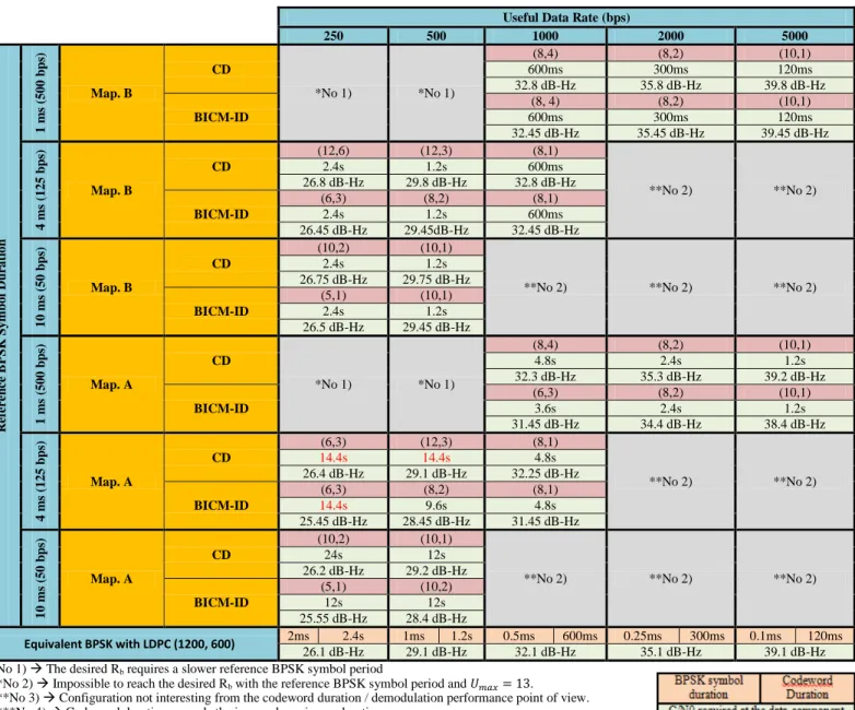
TABLE VII. CSK MODULATED SIGNALS WITH INCREASED USEFUL BIT RATE WITH RESPECT A BPSK REFERENCE SIGNAL BUT KEEPING THE ORIGINAL SYMBOL RATE.THE CODEWORDS CONTAIN 600 INVARIANT BITS (MAPPING B). THE CODEWORDS CONTAIN 600 OR MORE VARIANT BITS (MAPPING A).PROPOSED FOR
AWGN CHANNEL WITH COHERENT DEMODULATION.
Useful Data Rate (bps)
250 500 1000 2000 5000 R ef er en ce B PSK S y mbo l D u ra ti o n 1 m s (5 0 0 b p s) Map. B CD *No 1) *No 1) (8,4) (8,2) (10,1) 600ms 300ms 120ms 32.8 dB-Hz 35.8 dB-Hz 39.8 dB-Hz BICM-ID (8, 4) (8,2) (10,1) 600ms 300ms 120ms 32.45 dB-Hz 35.45 dB-Hz 39.45 dB-Hz 4 m s (1 2 5 b p s) Map. B CD (12,6) (12,3) (8,1) **No 2) **No 2) 2.4s 1.2s 600ms 26.8 dB-Hz 29.8 dB-Hz 32.8 dB-Hz BICM-ID (6,3) (8,2) (8,1) 2.4s 1.2s 600ms 26.45 dB-Hz 29.45dB-Hz 32.45 dB-Hz 1 0 ms ( 5 0 b p s) Map. B CD (10,2) (10,1)
**No 2) **No 2) **No 2) 2.4s 1.2s 26.75 dB-Hz 29.75 dB-Hz BICM-ID (5,1) (10,1) 2.4s 1.2s 26.5 dB-Hz 29.45 dB-Hz 1 m s (5 0 0 b p s) Map. A CD *No 1) *No 1) (8,4) (8,2) (10,1) 4.8s 2.4s 1.2s 32.3 dB-Hz 35.3 dB-Hz 39.2 dB-Hz BICM-ID (6,3) (8,2) (10,1) 3.6s 2.4s 1.2s 31.45 dB-Hz 34.4 dB-Hz 38.4 dB-Hz 4 m s (1 2 5 b p s) Map. A CD (6,3) (12,3) (8,1) **No 2) **No 2) 14.4s 14.4s 4.8s 26.4 dB-Hz 29.1 dB-Hz 32.25 dB-Hz BICM-ID (6,3) (8,2) (8,1) 14.4s 9.6s 4.8s 25.45 dB-Hz 28.45 dB-Hz 31.45 dB-Hz 1 0 ms ( 5 0 b p s) Map. A CD (10,2) (10,1)
**No 2) **No 2) **No 2)
24s 12s 26.2 dB-Hz 29.2 dB-Hz BICM-ID (5,1) (10,2) 12s 12s 25.55 dB-Hz 28.4 dB-Hz Equivalent BPSK with LDPC (1200, 600) 2ms 2.4s 1ms 1.2s 0.5ms 600ms 0.25ms 300ms 0.1ms 120ms 26.1 dB-Hz 29.1 dB-Hz 32.1 dB-Hz 35.1 dB-Hz 39.1 dB-Hz *No 1) The desired Rb requires a slower reference BPSK symbol period
**No 2) Impossible to reach the desired Rb with the reference BPSK symbol period and .
***No 3) Configuration not interesting from the codeword duration / demodulation performance point of view. ****No 4) Codeword duration exceeds the imposed maximum duration.


![Figure 6: Generation of the [ ] coefficient following a Loo distribution with Butterworth multipath [Burzigotti, 2008]](https://thumb-eu.123doks.com/thumbv2/123doknet/14366337.503635/8.893.461.838.83.299/figure-generation-coefficient-following-distribution-butterworth-multipath-burzigotti.webp)