HAL Id: hal-00080896
https://hal.archives-ouvertes.fr/hal-00080896
Submitted on 8 Oct 2007HAL is a multi-disciplinary open access
archive for the deposit and dissemination of sci-entific research documents, whether they are pub-lished or not. The documents may come from teaching and research institutions in France or abroad, or from public or private research centers.
L’archive ouverte pluridisciplinaire HAL, est destinée au dépôt et à la diffusion de documents scientifiques de niveau recherche, publiés ou non, émanant des établissements d’enseignement et de recherche français ou étrangers, des laboratoires publics ou privés.
New device to study unimolecular nucleation
Fabien Chirot, Sébastien Zamith, Pierre Labastie, Jean-Marc l’Hermite
To cite this version:
Fabien Chirot, Sébastien Zamith, Pierre Labastie, Jean-Marc l’Hermite. New device to study uni-molecular nucleation. Review of Scientific Instruments, American Institute of Physics, 2006, 77, pp.063108. �10.1063/1.2209957�. �hal-00080896�
“A new device to study unimolecular cluster nucleation”
F. Chirot, S. Zamith, P. Labastie, J-M. L’Hermite
Laboratoire Collisions, Agrégats, Réactivité (UMR 5589 CNRS-UPS), IRSAMC, Université Paul Sabatier Toulouse 3, 31062 Toulouse cedex 9, France
Abstract
We have developed an apparatus which allows measuring the sticking cross section of a neutral atom onto a mass selected charged cluster of known temperature. The main point is to reduce the kinetic energy dispersion in the mass selected cluster beam in order to work with ions of very low (near thermal) kinetic energy. A novel device is presented which focuses in energy with only a small loss in the beam intensity. An application is shown to the sticking of sodium atoms onto sodium clusters at an energy of a few tenths of an eV in the centre-of-mass frame.
PACS:
36.40.Jn Reactivity of clusters; 33.15.Ta Mass spectra 39.10.+j Atomic and molecular beam sources and techniques 36.40.Qv Stability and fragmentation of clusters
Introduction
The unimolecular dissociation of clusters has been widely investigated during the last two decades [1,2,3,4,5]. The basic idea of all experiments is rather simple: one measures the
number of atoms (or molecules) evaporated per unit time from an atomic (or molecular) cluster (for more simplicity, we restrict the following discussion to atomic clusters, but it can be applied without fundamental modification to molecular ones). The clusters are generally mass selected, and the variations of the evaporation rate with size and internal energy are measured. Evaporation can be either spontaneous [1], when the cluster is initially hot enough, or induced by an increase of its internal energy by photon absorption [2] or collision [3]. Such evaporation rates measurements give an insight into the thermodynamics of finite systems [4] in the frame of statistical models; they also give information on structural properties of clusters. Furthermore, the kinetic energy release distribution of neutral atoms emitted from photoexcited clusters can be analyzed [5].
Surprisingly, the opposite process, i.e. the sticking of a single atom onto a mass selected cluster, has never been investigated. Measurement of sticking cross sections is however of considerable interest. At a fundamental level, dissociation is closely linked to sticking according to the microreversibility principle [6]. From a more concrete point of view, nucleation processes are present everywhere in nature: for example, the nucleation of water molecules is responsible for cloud formation. Classical nucleation theory (CNT) is the most commonly used way to describe such nucleation processes. However, the discrepancy between this theory and experiment is often by orders of magnitude [7,8]. One crucial problem lies in a paradox of CNT. On the one hand, this theory is based upon macroscopic parameters, such as surface tension or latent heat. But on the other hand, one of its major postulates, the so-called “nucleation theorem” [9] states that there is a “critical size” n* which is a key parameter to describe the nucleation rate. The paradox is that n* is very small, ranging generally from ten to a hundred atoms, a range for which the macroscopic parameters used cannot be expected to give accurate results. For this reason, it is important to study the nucleation of clusters that are typically in this size range.
Furthermore, Schmidt et al [10] have shown a strong size dependence of the melting temperature of small sodium clusters. The initial phase (liquid or solid) of the clusters should influence the nucleation process. Thus it is important to study the influence of the cluster’s initial temperature on the sticking cross sections.
One possible reason for the lack of experimental data on the nucleation of clusters is that it is necessary to let cluster and atom collide at very low kinetic energy. If it is not the case, the cluster-atom collision leads to an effect exactly opposite to the expected one, i.e. the evaporation of an atom. The maximum allowed collision energy to observe sticking must be of the order of a few eV (depending on the size of the cluster). The practical problem is that the mass selection of clusters with classical methods (Time-Of-Flight (TOF) or quadrupole mass spectrometry) leads to much larger energy dispersions than a few eV.
Nevertheless, low energy collisions of mass selected clusters with atoms or molecules have already been carried out: ref. [11] deals with the fragmentation of M(H20)2+ (M=Fe, Co,
Au), in [12] the collision Ar+n=2-23 + 36Ar is studied, in [13] the reaction of H+(H2O)n=2-6 with
acetone is investigated and in [14] the authors measure the cross section for incorporation of ND3 in H+(NH3)n=3-9. In these experiments quite small clusters are produced in abundance in a
supersonic expansion. In reference [11] mass selection is made by a TOF and the energy spread is reduced by setting particular temporal shapes to the extracting acceleration voltages. However, it is not enough to get kinetic energies of a few eV in the laboratory frame. To get a smaller energy spread, the authors take advantage of the incoming ion beam being perpendicular to the acceleration plates: the thinner the beam, the lower the energy spread of the ions. Unfortunately, this is at the cost of a severe decrease in the intensity of mass-selected clusters. In references [11, 12, 13] the authors use the so-called guided ion beam (GIB) method. The mass selection of both reactant and products is done by quadrupole mass filters. Without any additional device, the kinetic energy spread is about 10 eV [11]. In order to
reduce it to a few eV, Kawai [12] and Orii [13] use a Bessel box energy analyzer. This last device does not reduce the energy spread, but selects the fraction of the clusters that have the desired energy to a given accuracy. Once again, it reduces the number of mass-selected clusters. This may be a crucial drawback when the amount of clusters is very low for an individual mass.
For experiments such as described above, the beam intensity is not an issue since they are performed with a supersonic expansion. In our case however, since we want to control the clusters temperature from 150 K to 500 K, we cannot use a supersonic expansion. Furthermore, we want to explore clusters made of several hundreds atoms. For these sizes the cluster yield is drastically lower than for small clusters produced in a supersonic expansion. Thus, these two reasons force us to work with relatively low beam intensities, so that it is crucial not to introduce too many losses when slowing down the clusters to the desired kinetic energy.
In this paper, we present a simple electrostatic device for generating thermalized mass selected clusters with kinetic energies of only a few eV in the laboratory frame (a few hundredth eV for a 100-atom cluster in the centre-of-mass frame). The key point is that no energy selection is made so that a very good transmission trough the apparatus is obtained. The device performs an “energy focusing” that gives the same energy, to a good precision, to a large part of the clusters. We have applied successfully this technique to the sticking of individual sodium atoms onto sodium clusters and we measured absolute sticking cross section.
In section I, we give an overview of the experimental setup. We develop the principle of our method in section II, and section III is devoted to a detailed description of the device. Finally we present the first experiments applied to the sticking of sodium atoms onto sodium
clusters in section IV. Section V is devoted to a discussion of the relative advantages of our setup.
I. General overview of the experimental setup
A sketch of the experimental setup is shown in Figure 1. Sodium clusters are produced and ionized in a gas aggregation source. This source has been extensively used in previous cluster physics experiments [15] and will not be described in detail. Briefly, sodium is heated up to 580 K in a crucible in contact with helium gas cooled down to 170 K. The helium pressure is 1 mbar whereas the sodium vapor pressure is of the order of 10-2 mbar. Cluster formation occurs due to the condensation of the hot sodium vapor in the cold buffer gas. A 150 V potential is applied to the crucible, creating a hollow cathode discharge that ionizes the clusters.
Next they enter a copper thermalization chamber (length 150 mm, diameter 20mm) through a 10 mm hole. Clusters are thermalized by collisions with helium atoms being themselves at the chamber temperature. The helium pressure in this chamber is of the order of 1 mbar. This leads to an average number of collisions between the clusters and the helium atoms on the order of 104, thus insuring a good thermalization. The temperature of the chamber can be varied from 150 to 500 K. The output hole of the chamber is an iris diaphragm whose diameter can be adjusted in order to maximize the cluster yield. The working diameter is of the order of 5 mm. It must not be too small in order to avoid supersonic expansion that would cool the internal degrees of freedom of clusters, and then change their temperature. This feature limits the intensity of the beam. We estimate that for a given mass we produce 105 ions per second.
Charged clusters then enter the first mass selection stage through a 1 mm skimmer (Beam Dynamics). The clusters are accelerated in a three-plate Wiley-McLaren type device (WML) (see figure 2). The distances between plates are 10.9 mm and 13.5 mm. In order to define very precisely the potentials we use 90% transmission nickel mesh (Labelcomat, 70 lines/inch).
The next two stages labeled “energy focusing” and “braking” on Figure 1 reduce the kinetic energy spread of a mass selected cluster and allow adjusting its kinetic energy to low values. This is the crucial point of the experiment that will be described in detail in section II. After these two stages, we have mass selected thermalized clusters of known kinetic energy. Slow clusters then enter the collision cell (50 mm long, 5mm input diameter, 30 mm diameter). This cell contains a sodium vapor whose density is controlled by setting its temperature.
Under the right conditions, sticking of one or several atom(s) onto the clusters occurs. The collision products are analyzed in a second Time-Of-Flight mass spectrometer. A reflectron improves its resolution up to about 4000. Its large angular acceptance (the entrance diameter is 60 mm) reduces losses due to transverse motion. The geometry of the three-plates acceleration zone has been optimized in order to collect efficiently the ions. Simulation shows that the spatial dispersion after the cell is about 20 mm. Thus the distance between the first two accelerating plates is 20 mm in order to avoid losses. The distance between the last two plates is 30 mm. These distances are larger than those of the first WML. Although we use nickel mesh on the first two plates, these rather large distances cause spatial dispersion that is compensated using an Einzel lens just after the end plate. The detector is a tandem microchannel plates device.
If the collision energy is low enough, the new clusters do not evaporate before they are detected. The sticking cross section can then readily be deduced from the size distribution.
II. Principle of the energy focusing
Let us first recall some key points of the operation of a WML [16]. We refer the reader to Figure 2a for notations. We consider clusters of a given mass m and charge q. At a time
T=0, the voltages Vs and Vd are applied to the acceleration plates. The clusters then acquire a
potential energy U which depends on the initial abscissa s of the cluster between the plates at
Vs and Vd. Specifically, if Es=(Vs-Vd)/s0 and Ed=Vd/d0 are the two accelerating electric fields,
U=qsEs+qd0Ed, with s the abscissa of the cluster defined leftwards from the plate at Vd. The
particular design of the acceleration region with two fields allows a small relative dispersion of energy. This dispersion is however much too high for our purposes.
Now, the distance D from the last accelerating plate reached after a time T is:
(
)
( )
(
)
(
d)
d d s d qE E qd U U qE U qE E qd U U m T U D 2 / 1 0 2 / 1 2 / 1 0 2 / 1 2 / 1 2 / 1 2 2 2 2 2 − − − + − = (1)for a cluster of mass m and charge q. The relation between the position of a cluster and its kinetic energy is displayed in Figure 2b, for different times T. In order to characterize the effects of the dispersion in energy, we develop D(U) in a Taylor expansion around U=U0, the
energy of a cluster starting from the middle between the first two plates, s=s0/2.
( )
( ) (
) (
)
(
)
3 0 2 0 0 0 U U U U 0U U U D U D = +α − +β − + −Because of the form of equation (1), coefficients α and β depend linearly on time. Hence they become zero at different times T. For the usual operation of WML mass spectrometers, the
detector is placed at a distance such that α is zero. This is the time focus point. Here we want a focus in energy. By applying a pulsed electric field Efoc= - 1/(αq) at some distance when the
selected clusters arrive, it is easy to compensate for the linear dispersion given by α. If we choose to apply the field at the time Tfoc where β is zero, the energy dispersion is compensated
up to third order. In other words, the condition
0 2 2 = ∂ ∂ U D (2)
determines a time Tfoc and a distance Dfoc where a voltage Vfoc corresponding to Efoc (see
Figure 2a) is applied. Tfoc, Dfoc, and Efoc are given by the following expressions:
(
)
(
) ( )
2 1/2 2 / 3 0 2 1 2 s d s d s foc qE E E s E E d m T = −(
)
(
)
[
(
)
]
+ − + − + = 1/2 0 2 / 1 2 / 3 0 2 2 / 1 0 1 1 2 s d d s d s d s s d foc s E E s dE E E E E E s d E E d s D(
)
(
)
(
)
1 2 / 3 0 0 2 / 1 0 2 3 2 − + − − − = d d d s d s d foc E qdE U qdE U E E U E E EDfoc depends only of the ratio Ed/Es. Moreover, it should be noted that Dfoc and Vfoc do not
depend on the mass. This is important: to change the mass under study, we only need to change Tfoc. A single mass corresponds to a given Tfoc. Thus, only this mass has an energy
dispersion low enough to be slowed down without being spread out in time: The energy focusing also acts as a mass selection.
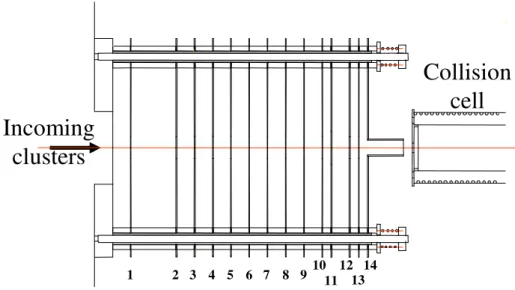
Description of the device
The device displayed on Figure 3 performs both energy focusing and braking of the ions. It is made of 14 stainless steel plates of 12 cm diameter held by four steel rods housed with a glass tube to ensure electric insulation. A 12 mm hole is drilled at the center of each plate (except the plate n°11 whose hole is 18 mm diameter). The distance between plates 1 and 2 is 25 mm. Plates 2 to 10 are separated by 10 mm. The distance between plates 10 and 11, 12 and 13, 13 and 14 is 5 mm and between 11 and 12 is 10 mm.
The focusing voltage is applied between the first two plates (n°2 is grounded) and a 90% transmission nickel mesh (Labelcomat, 70 lines/inch) is used to define a more homogeneous electric field.
Plates n°2 to 10 of the apparatus are used to slow down the ions. An exponential decelerating potential is applied (Vi=V0(1-e-i/Γ) for the plate i) in order to minimize spatial
defocusing [11]. The exponential shape of the potential is obtained by connecting the plates with appropriate resistors. The end plates n°10, 12, 13 and 14 are set to the same potential in order to define a zero-field zone (we will see later why such a zone is necessary). A 20mm long cylindrical extension is added on plate n°14 in order to increase the length of this zone. An additional plate (n°11) can be set to a potential Vfs different from the plates n°10, 12 and
13: it acts as an Einzel lens by reducing losses due to transverse motion.
Although it would theoretically improve the performance, mesh cannot be used on the plates n°3 to 14 for two reasons: first, the total transmission would be too low; second, ions kinetic energy is reduced and the field distortion would produce a drastic spatial defocusing [17,18].
Time synchronization is very important since all voltages must be pulsed. The repetition rate is 100 Hz. High voltages are provided by low noise power supplies (Bertan model 205B) and pulses are generated by TTL driven fast high voltages switches (Behlke HTS 51) whose rise time is lower than 10ns. The value of pulsed voltages is defined to about ± 0.2 V and the pulse-to-pulse temporal jitter of the switches is less than 1 ns. The synchronized TTL signals are provided by a timer card (National Instrument) clocked to 80 MHz.
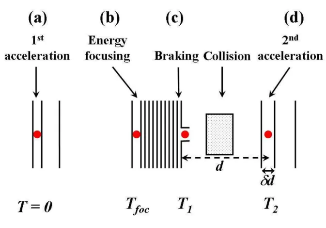
Figure 4 displays the main sequences of the operation. At T=0 the voltage pulses are applied on the two accelerating plates (Figure 4a). For a given mass, the voltage Vfoc must be
applied at time Tfoc. At this time, a voltage Vb is already established on the exponential barrier
(Figure 4b). The value of this voltage is chosen as a function of the desired kinetic energy. It is straightforward to calculate the appropriate value: if the mean kinetic energy after focusing is Ek0 and if Ekis the desired kinetic energy, Vb has to be set to (Ek0-Ek)/q.
However if this were all we did, the clusters would be accelerated again after the end of the braking device since the collision cell is grounded. Thus it is necessary to shut down Vb
at time T1, when the clusters are in the zero-field zone (Figure 4c). This has to be done very
rapidly so that the voltage is zero to a good accuracy when the clusters go out of the device. That’s why a careful study of the time response of the system has to be done. Since the resistor chain used to provide the exponential barrier contains high resistances, the parasite capacitances due to the plates have to be considered. It’s easy to show that the best performance is obtained for equal RCs at each stage. Adjustable capacitances have been added to achieve this.
Once the potential barrier is shut down, the clusters enter the collision cell and reach the last mass selection stage where they are accelerated again at time T2 (Figure 4d).
IV. Experimental results
Energy focusing
The velocity distribution of slow clusters can be measured directly in our setup. When
Vb has been shut down at time T1, the clusters mean position is x1. When the 2nd acceleration
voltages are switched on at time T2, the mean position of the ions is x2 (x2- x1 = d in Figure 4).
The clusters mean velocity is then v = (x2- x1)/(T2-T1). By recording the ion signal as a
function of T2, one can determine the velocity distribution.
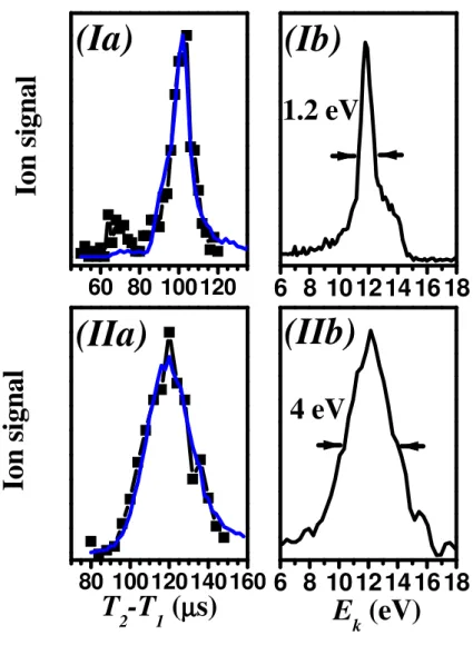
Figure 5 displays two examples of ion yield as a function of T2 together with their
corresponding kinetic energy distributions. Figure 5 I) concerns Na82+. The experimental
parameters are set to the following values: Vs = 745 V, Vd = 520 V, Vfoc = 198 V, Tfoc= 37.9
µs, the potential barrier is set to Vb = 702.2 V and the spatial focusing voltage to Vfs = 729.6
V, they are shut down at T1 = 90 µs. The measured kinetic energy is 12±0.6 eV. Figure 5 II)
shows Na100+ signal obtained with Vs = 725 V, Vd = 519 V, Vfoc = 219 V, Tfoc= 40.8 µs, the
potential barrier is set to Vb = 728.5 V and the spatial focusing voltage to Vfs = 541.7 V, they
are shut down at T1 = 90 µs. The fitted curves are obtained from a numerical simulation of the
signal detected in our second TOF as a function of T2. The simulation takes into account the
distributions of initial positions s in the first acceleration stage and the initial velocity distribution of the clusters. Furthermore we introduce noise on times and voltages.
The main difference from case I) to II) is that they are obtained under two different spatial focusing operating modes. Spatial focusing is necessary: when clusters are slowed down, one can no longer neglect their transverse motion. The entrance diameter of the cell being 5 mm, the beam has to be refocused so that all clusters go through the cell. The refocusing is achieved by setting plate n° 11 to a potential different from the neighboring ones. Doing so, it acts as an Einzel lens. The time at which the potential barrier has to be shut
down is affected by this potential: the clusters take more (less) time to reach the zero-field zone for a higher (lower) potential. We estimate that the transmission is increased by about a factor 4 in case II) when spatial focusing is achieved.
Let us now detail the difference between mode I) and mode II). In I), the voltage Vfs is
set to a value larger than the potential barrier Vb by a few tens volts whereas in II) Vfs is
smaller than Vb by hundreds volts. The first mode results in an excellent focusing provided
that the cluster kinetic energy is very close to the mean value Ek0. In the second mode, this
point is less stringent. SIMION [19] simulations show that the margin of tolerance δE around Ek0 is about ±0.7 eV in the first case and 7 eV in the second case. In case I) the energy
dispersion is smaller because clusters whose energy is different from Ek0 by more than 0.7 eV
are spatially discarded. The signal is obviously reduced but remains comfortable enough to work. In case II), the width of 4 eV is the true total dispersion of the apparatus. The energy spread could theoretically be as low as 0.1 eV, but is larger than this for several reasons. First, the applied voltages and delays are subject to the noise mentioned in the previous section. However, this gives a small dispersion, of the order of ±0.25 eV. The most important source of energy spread is the initial velocity distribution of clusters in the beam. As mentioned in section II, the energy focusing relies on a linear relation between the position and the kinetic energy at time Tfoc. Any initial velocity distribution will induce a deviation from it. Indeed,
clusters starting from the same initial position s but having different initial velocities will end up at slightly different positions between the focusing plates at time Tfoc. In figure 5 II), Na100+
clusters are thermalized at 143 K. In our experiment, clusters are seeded in helium; simulation shows that, although their mean velocity is shifted to the mean velocity of helium, their translational temperature remains the same: the FWHM of their velocity distribution is of the order of (2kT/m)1/2 = 40 m.s-1.This is exactly the value deduced from the fit in Figure 5 IIa). One can actually choose between mode I) and mode II): if the ion yield is large enough, it is
possible to select the mode I), for which the energy resolution is better; on the other hand mode II) provides a better ion yield.
It should be noted that, for a given T2, another feature limits the energy spread of the
detected ions: only clusters that are present at T2 between the first two plates of the second
TOF are detected. Let v be the velocity of the cluster across the cell, Ek the corresponding
kinetic energy, d the distance from the zero-field zone to the middle of the accelerating region, and δd the width of this region (see figure 4). The restriction above mentioned is
approximately defined by δEk/Ek=2δv/v<δd/d. δd/d is about 20%, so δEk/Ek<40%. It
corresponds to δEk≈4 eV for the example given in figure 5 II).
In cases where a supersonic expansion can be used to generate clusters, our apparatus is likely to provide better performances since we have demonstrated that the main limitation to the energy focusing is the initial velocity dispersion.
We estimate the overall transmission through the device to be more than 20% for Na82+ slowed down to about 10 eV (using spatial focusing mode II)). This corresponds to
about 3 clusters detected per pulse. This allows us to observe sticking under very good conditions.
Sticking of sodium atoms onto sodium clusters
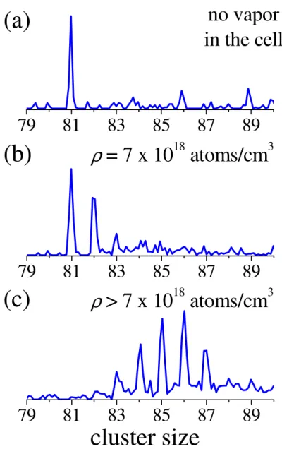
Figure 6 displays the first experimental sticking results. We select Na81+ thermalized at
158 K and with a kinetic energy Ek of 20 eV in the laboratory frame (corresponding to a
collision energy of about 0.3 eV). The experimental values are: Vs = 725 V, Vd = 520 V, Vfoc =
222 V, Tfoc= 36.9 µs, Vb = 719 V, Vfs = 205 V, T1 = 72 µs, T2 = 162 µs.
Then we increase gradually the temperature from 293 K to 533 K, and thus the density of atoms, in the collision cell.
Without vapor in the collision cell (Figure 6a), there is no sticking and only Na81+ is
detected. For a density ρ = 7.1018 atoms/cm3(Figure 6b), Na82+ and a small amount of Na83+
are produced. If one increases the density, up to 6 sticking events can be observed (Figure 6c). Under these conditions the parent clusters are all converted to higher mass species, the maximum size being Na87+.
This “saturation” of nucleation is actually easy to explain if we focus on the lifetimes of the nucleation products. At each sticking event An+A⇒An+1, the internal energy of the
incoming cluster An is increased by Dn+1+EcCM, where Dn+1 is the dissociation energy of An+1
and EcCM is the collision energy in the center of mass frame. In our case, Dn+1>>EcCM. The
dissociation energies do not vary much from one size to another for clusters of a hundred atoms, so let’s note it D. Thus, starting from a cluster of size p and internal energy E*p, the
internal energy E*q of a cluster of size q obtained by sticking is approximately E*q=E*p +
(q-p)D. From previous experiments, the relation between internal energy and mean evaporation
time is well known for sodium clusters [20]. As we know the initial temperature of Na81+, it is
easy to calculate E*81 and E*81+n. In our experiment, clusters are detected at the right time of
flight only if they do not evaporate before they enter the reflectron. The propagation time τ from the cell to the reflectron, which depends on the selected kinetic energy, the voltages and the mass, is easy to calculate. The first undetected mass m has an internal energy E*m leading
to a lifetime smaller than τ. Using the parameters of [20], this simple theory gives an estimate that perfectly agrees with experimental observation. Moreover, the value of m depends on the initial temperature. The agreement between theory and experiment indicates that the cluster has been thermalized to the expected value. Note that this time τ is particularly small in our experiment (it is about 150 µs for the considered conditions). This feature reduces the awkward problem of spontaneous dissociation.
The measurement of the sticking probability for a cluster of size n leads to the absolute nucleation cross sections σ(n). Let I be the amount of clusters that have not undergone
sticking, and I0 the total amount of incoming clusters. For example, I0 is the sum of the areas
of all the peaks of Figure 6, whereas I is the area of the first one. Let Ek denote the kinetic
energy of the incoming clusters in the laboratory frame, d the length of the cell and ρ the density of atoms in the cell as deduced from the vapor pressure of sodium at the temperature of the cell T. A simple calculation gives σ(n):
( )
(
0)
1 1/2 1 Ln − + × − = k b E T nk d I I n ρ σFor the nucleation reaction Na81++Na ⇒ Na82+ we determined a cross section of 200 Å2. For
this preliminary result, the error bar is quite difficult to estimate. In particular, the density of sodium vapor in the collision cell needs to be known with a better accuracy. The measurement of nucleation cross sections for sodium clusters as a function of the size is the next step of the experiment, but it is out of the scope of this paper and will be the subject of a forthcoming publication.
V. Comparison with alternative devices
We have already briefly described in the introduction other methods to get low energy collisions.
One alternative device also uses a TOF [11] but our setup provides a better energy resolution [21]. GIB devices use quadrupoles and octopoles [12,13,14]. Without any “slicing” (i.e. without Bessel Box), they provide an energy dispersion of the order of 10 eV. Our setup is better on this point. Another advantage of our method is that the time between collision and
detection, and thus post collisional evaporation, is reduced compared to GIB devices. On the other hand, their energy resolution is better than our when using a Bessel box. Concerning the overall transmission, we could not find quantitative data concerning the GIB method. Anyway, when using a Bessel box the transmission is certainly much smaller than our.
To conclude, our apparatus is a competitive alternative to GIB. It seems to provide performances at least as good as GIB when no slicing is made. On the other hand, a GIB apparatus with a Bessel Box provides an excellent energy resolution that we are not able to reach with our effusive source. Nevertheless, a better energy resolution could be obtained with our setup using a supersonic expansion.
Finally, let us point out that our device is simpler and cheaper than a GIB apparatus (that uses two octopoles, two quadrupoles and a Bessel box).
Conclusion
We have developed a new device to produce mass selected thermalized clusters with very low kinetic energy. Energies as low as 10±2 eV in the laboratory frame are routinely obtained with a comfortable ion yield. We used successfully this device for measuring the absolute sticking cross section of sodium atoms onto sodium clusters. It opens the way to new investigations in the physics of nucleation processes.
Acknowledgements
We thank M. Gianesin, Ph. Paquier, L. Polizzi, G. Trénec and W. Volondat for technical support. The authors are grateful to B. Whitaker for a critical reading of the manuscript.
1st Mass selection Thermalization Energy focusing Ions braking Collision 2 nd Mass selection Charged clusters production
Figure 1: Experimental setup.
(b)
E
n
er
g
y
T
foct = 0
Position
d
0s
0V
sV
d0
V
foc0
Energy
focusing
Acceleration
Ionized
clusters
(a)
D
focFigure 2: Principle of energy focusing.
(a) Schematic view of the experimental implementation of the energy focusing. Charged clusters are accelerated at t=0 in a Wiley-McLaren type device. At a distance Dfoc an
appropriate electric field is applied that compensates for the energy spread of the accelerated clusters. The dimensions are: S0 = 10.9 mm, d0 = 13.5 mm, Dfoc = 257.5 mm.
(b) Calculated evolution of the kinetic energy versus position from the initial acceleration (t=0) until the time Tfoc at which Vfoc is applied. For clarity the horizontal scale
has been enlarged for each distribution in order to accentuate the deviation from linearity. The relation between energy and position is linear initially, and then becomes non-linear. At
distance Dfoc this relation becomes linear again and an appropriate voltage Vfoc allows energy focusing.
Incoming
clusters
1 2 3 4 5 6 7 8 91011121314Collision
cell
Figure 3: Design of the focusing device. The focusing voltage is applied between the plates
n°1 and 2. Plate n°2 is grounded. The voltage necessary to slow down the clusters is applied exponentially from plate n°2 to plate n°10. Plates n°10, 12, 13 and 14 are set to the same potential. Plate 11 is set to a different voltage for spatial focusing purpose. The distance between plates 1 and 2 is 25 mm. Plates 2 to 10 are separated by 10 mm. The distance between plates 10 and 11, 12 and 13, 13 and 14 is 5 mm and between 11 and 12 is 10 mm. The cylindrical extension is 20 mm long. The cell is 5 mm away from the end of the device.
Figure 4: Illustration showing the different delays involved in the operation:
(a) T=0: voltages are applied on the first acceleration stage. (b) Tfoc: the energy focusing voltage is switched on.
(c) T1: the potential barrier voltage is switched off.
60 80 100 120
6 8 10 12 14 16 18
(Ib)
(Ia)
I
o
n
s
ig
n
a
l
1.2 eV
80 100 120 140 160
(IIa)
I
o
n
s
ig
n
a
l
T
2-T
1(
µµµµ
s)
6 8 10 12 14 16 18
(IIb)
4 eV
E
k(eV)
Figure 5: Final kinetic energy distribution measured for I) Na82+ and II) Na100+. Cases I) and
II) illustrate two different spatial focusing conditions (see text).
(a) Experimental ion signal (squares) together with a fit (solid line) as a function of the delay (T2-T1). The theoretical distribution is noisy due to a statistical sampling of voltages and time.
The amount of variation is deduced from experimental measurements (see text for further details).
(b) Kinetic energy distribution deduced from the fit shown in (a). Na82+ clusters are slowed
79
81
83
85
87
89
(b)
(c)
ρ
> 7 x 10
18atoms/cm
3cluster size
79
81
83
85
87
89
(a)
ρ
= 7 x 10
18atoms/cm
379
81
83
85
87
89
no vapor
in the cell
Figure 6: Experimental sticking of sodium atoms onto Na81+ as a function of the atomic
References
1 J.-M. L’Hermite, F. Rabilloud, L. Marcou, P. Labastie E.P.J. D 14, 323-330 (2001) 2 C. Brechignac, P. Cahuzac, J. Ph. Roux, J. Chem. Phys. 88(5) 3022-3027 (1988)
3 G. A. Breaux, R. C. Benirschke, M. F. Jarrold, J. Chem. Phys. 121(13), 6502-6507 (2004) 4 M. Schmidt, R. Kusche, W. Kronmüller, B. von Issendorf, H. Haberland, Phys. Rev. Lett 79
(1) , 99 (1997)
5 C. Brechignac, Ph. Cahuzac, B. Concina, J. Leygnier, Phys. Rev. Lett. 89(20), 203401/1-4
(2002)
6 P. C. Engelking, J. Chem. Phys. 87(2), 936 (1987)
7 M. A. Zondlo, P. K. Hudson, A. J. Prenni, M. A. Tolbert, Ann. Rev. Phys. Chem. 51, 473
(2000)
8 J. Wölk, R. Strey, J. Phys. Chem. B 105, 11683 (2001) 9 D. Kashchiev, J. Chem. Phys. 76, 5098 (1982)
10 M. Schmidt, R. Kusche, B. von Issendorf and H. Haberland, Nature, 393, 238 (1998) 11 O. Sublemontier, L. Poisson, P. Pradel, J. M. Mestdagh, and J. P. Visticot, J. Am. Soc.
Mass. Spectrom. 11, 160 (2000)
12 M. Ichihaschi, S. Nonose, T. Nagata, T. Kondow, J.Chem.Phys 100 (9), 6458 (1994) 13 Y. Kawai, S. Yamaguchi, Y. Okada, K. Takeuchi, International Journal of Mass
Spectrometry 220, 375 (2002)
14 T. Orii, Y. Okada, K. Takeuchi, M. Ichihashi, T. Kondow, J.Chem.Phys. 113(18), 8026
(2000)
15 « Clusters of Atoms and Molecules, Theory, Experiment » Springer Series in Chemical
16 W. C. Wiley and I. H. McLaren, Rev. Sci. Instrum. 26(12), 1150 (1955)
17 T. Bergmann, T. P. Martin, H. Schaber, Rev. Sci. Instrum. 60(3), 347-349 (1989) 18 T. Bergmann, T. P. Martin, H. Schaber, Rev. Sci. Instrum. 61(10), 2592-2600 (1990) 19 D. A. Dahl, J. E. Delmore, and A. D. Appelhans, Rev. Sci. Instrum. 61(1), 607-609 (1990) 20 C. Brechignac, P. Cahuzac, J. Leygnier, J. Weiner, J. Chem. Phys. 90(3), 1492-1498 (1989) 21 J. M. Mestdagh, private communication.