Publisher’s version / Version de l'éditeur:
Vous avez des questions? Nous pouvons vous aider. Pour communiquer directement avec un auteur, consultez la première page de la revue dans laquelle son article a été publié afin de trouver ses coordonnées. Si vous n’arrivez pas à les repérer, communiquez avec nous à [email protected].
Questions? Contact the NRC Publications Archive team at
[email protected]. If you wish to email the authors directly, please see the first page of the publication for their contact information.
https://publications-cnrc.canada.ca/fra/droits
L’accès à ce site Web et l’utilisation de son contenu sont assujettis aux conditions présentées dans le site LISEZ CES CONDITIONS ATTENTIVEMENT AVANT D’UTILISER CE SITE WEB.
Internal Report (National Research Council of Canada. Institute for Research in
Construction), 2001-04-01
READ THESE TERMS AND CONDITIONS CAREFULLY BEFORE USING THIS WEBSITE. https://nrc-publications.canada.ca/eng/copyright
NRC Publications Archive Record / Notice des Archives des publications du CNRC :
https://nrc-publications.canada.ca/eng/view/object/?id=0c555024-644f-49ce-b656-45f2139b8c36 https://publications-cnrc.canada.ca/fra/voir/objet/?id=0c555024-644f-49ce-b656-45f2139b8c36
NRC Publications Archive
Archives des publications du CNRC
For the publisher’s version, please access the DOI link below./ Pour consulter la version de l’éditeur, utilisez le lien DOI ci-dessous.
https://doi.org/10.4224/20386393
Access and use of this website and the material on it are subject to the Terms and Conditions set forth at
Small-scale and full-scale fire tests of four construction materials
Sumathipala, K.; Carpenter, D. W.; Monette, R. C.; Séguin, Y. P.; Lougheed,
G. D.
i
I
National Research Conseil national
I * h
Council Canada de recherches CanadaR427
Institute for lnstitut deResearch recherche in Construction en construction
Small-Scale and Full-Scale Fire Tests of
Four Construction Materials
K. Sumathipala, D.W. Carpenter, R.C. Monette, Y.P. Seguin and
G.D. Lougheed
Internal Report 824
SMALL-SCALE AND FULL-SCALE FIRE TESTS OF FOUR CONSTRUCTION MATERIALS
K. Sumathipala, D.W. Carpenter, R.C. Monette, Y.P. Seguin and G.D. Lougheed
ABSTRACT
This report summarizes the results from bench-scale and full-scale fire tests of 4
construction materials. The tests were conducted as part of a joint research project between Forintek Canada Corporation and the National Research Council of Canada. The
4 materials evaluated were extruded polystyrene, oak-veneered plywood, hardboard with
imitation stucco coating and fire-retardant-treated plywood. The srnall-scale fire tests were conducted using a cone calorimeter and the LIFT test procedure. In addition, a series of full-scale room/corner tests were conducted.
SMALL-SCALE AND FULL-SCALE FIRE TESTS OF FOUR CONSTRUCTION MATERIALS
K. Sumathipala, D.W. Carpenter, R.C. Monette, Y.P. Seguin and G.D. Lougheed
INTRODUCTION
The small-scale and full-scale fire tests described in this report were conducted as part of a joint research project between Forintek Canada Corporation and the National Research Council of Canada. As part of this project, four construction materials were evaluated using small-scale and full-scale fire tests. The 4 materials evaluated were extruded polystyrene, oak-veneered plywood, hardboard with imitation stucco coating and fire-retardant-treated plywood. The small-scale fire tests were conducted using a cone calorimeter
[I]
and the LIFT test procedure 121. In addition, a series of full-scale roomlcorner tests were conducted using the I S 0 9705 [3] and the proposed ASTM test methods 141.BACKGROUND
Noncombustible Building Materials
Building codes and other regulations often put restrictions on the ignitability and
combustibility of building materials as one approach to control fires in buildings. If fires are difficult to ignite, remain localized once ignited or spread and burn slowly, then building occupants are more likely to have sufficient time to escape.
Building materials are classified within the National Building Code of Canada (NBCC) [5] as either combustible or noncombustible. In Part 3 of the NBCC, a degree of fire safety is attained by prescribing the use of noncombustible materials for some buildings, particularly high buildings or buildings with large areas.
At present, the materials for use in noncombustible construction must meet the acceptance criteria of CAN4-S114 [6]. This test method for non-combustibility of building materials has a number of limitations, however. They are:
it is a severe passlfail test which does not provide quantitative data, it is limited to elementary building materials,
CAN4-SI 14 can readily differentiate between noncombustible building materials such as steel, concrete and plaster and combustible wood, plastic and asphalt building materials. However, there are building materials such as gypsum board, which are generally
acknowledged as being acceptable for use in buildings of noncombustible construction but which are classified as combustible by the noncombustibiltiy test. As a result, the limited use of combustible materials, in a building required to be of noncombustible construction, is permitted in the NBCC (Articles 3.1 5.2 to 3.1 .I 5.1 8, 3.1 .I 3.4 and 3.2.2.1 3) [5]. However, there is no test method for evaluating new materials with limited combustibility for use in buildings required to be of noncombustible construction.
Degrees of Combustibility
In 1976, the Canadian Commission on Building and Fire Codes requested that the
Underwriters' Laboratories of Canada Committee on Fire Tests, develop a test method to evaluate building materials in terms of degree of combustibility. Efforts by a ULC Task Group to adapt the existing noncombustibilty test were not successful. The Task Group subsequently investigated the use of the Ohio State University apparatus and later the cone calorimeter for ranking building materials, in terms of their degree of combustibility. This work led to the publication of two test methods by the ULC Committee on Fire Tests in 1992: ULC-S128 171, CANIULC-S135-92 [8].
Bench-Scale and Full-Scale Reaction-to-Fire Tests
In recent years, a number of bench-scale reaction-to-fire tests have been developed for evaluating building materials in terms of their thermophysical and thermochemical behaviour. This includes: the cone calorimeter [I], which can be used to determine the ignitability, heat release rate, mass loss rate, effective heat of combustion and visible smoke development of materials; and the LIFT test procedure [2], which can be used to determine the minimum surface flux and temperature necessary for ignition and for lateral flame spread. Results from these small-scale tests are frequently used as input to numerical models to predict the performance of the material in large-scale fires.
In addition to the bench-scale fire tests, standard roomlcorner tests were developed as a full-scale reaction-to-fire test for evaluating building materials. These full-scale fire tests are also used as the basis for evaluating the validity of bench-scale fire tests.
Project Scope
During the development of the CANIULC-335-92 test method, a number of building materials were tested [9]. These tests were, however, directed primarily to test method development. Systematic tests to develop the technical databases for use in addressing issues and questions regarding the referencing of the degrees of combustibility test method in the NBCC were not conducted. This project is one of a series of joint projects with the Canadian construction industry and material suppliers, to address issues related to the adoption of a performance-based test method for determining degrees of combustibility of building materials.
In this project, bench-scale and full-scale fire tests were conducted on 4 construction materials. The 4 materials evaluated were extruded polystyrene, oak-veneered plywood, hardboard with imitation stucco coating and fire-retardant-treated plywood. Small-scale fire tests were conducted using a cone calorimeter [ I ] and the LIFT test procedure [2]. In addition, a series of full-scale roomlcorner tests were conducted using the I S 0 9705 [3] and the proposed ASTM test methods [4].
DESCRIPTION OF MATERIALS
The materials tested are listed in Table 1. All material specimens were supplied by Forintek Canada Corporation, Ottawa, Canada.
Table 1: List of materials tested on small- and full-scale.
DESCRIPTION OF TEST METHODS Material ID A B C D E
The building materials listed in Table 1 were subjected to the following small-scale and full- scale fire tests.
Cone Calorimeter Tests
Material
Extruded polystyrene foam Extruded polystyrene foam Oak-veneered plywood
Hardboard, imitation stucco coating Fire-retardant-treated plywood (Dricon)
Cone-calorimeter tests were conducted in accordance with ASTM El354
[Id.
For eachmaterial, tests were conducted using 3 heating fluxes; 25 kw/mz, 50 kW/m and 75 kw/rn2. The 50 kw/m2 exposure is the heating flux specified in CANIULC-S135 [8].
In addition to the cone calorimeter tests conducted by NRC, selected materials were tested by ORTECH International using a heating flux of 50 kw/m2. The materials tested by ORTECH were: oak-veneered plywood, hardboard with imitation stucco coating and fire- retardant-treated plywood. The results of the tests conducted by ORTECH are included in this report. Thickness (mm) 25 50 12.5 10 12.5 Density (ks/m3) 29 29 480 930 560
In tests conducted by both ORTECH and NRC, data collection was continued after the flames self-extinguished to investigate the use of cone calorimeter data collected for a fixed time period.
LIFT Apparatus Test
Bench-scale fire tests were conducted in accordance with ASTM
E1321-90
[2].
Using thistest procedure, the minimum heat flux for ignition, below which the material would not ignite, was determined. Ignition time flux profiles were obtained for a range of heat fluxes above this minimum incident flux. The rate of flame spread tests were measured at a heat flux
level 5 kwlm2 above the minimum heat flux for ignition. ASTM Full-Scale Room Corner Fire Test
Full-scale roodcorner fire tests were conducted in accordance with the proposed ASTM
standard
(41.
The proposed ASTM protocol was published as a proposed standard in1982
and was used for the ASTM Institute for Standards interlaboratory test program
[lo].
The roodcorner test facility was
3.6
m long,2.4
m wide and2.4
m high. The room has a single doorway0.8
m wide and2
m high for ventilation in the center of one of the2.4
m by2.4
m end walls.A propane sand burner, located in a corner of the test facility, was used as the ignition source (Figure
1).
The ignition source was adjusted to produce40
kW during the initial phase of the test. After 5 minutes, the ignition source was increased to160
kW, if flashover did not occur during the first 5 minutes.The products of combustion were collected using a hood located above the doorway. The hood was attached through an exhaust duct to a fan. Gases were sampled from the exhaust duct and used to determine the rate of heat release in the room from the test material, and the production of carbon monoxide and carbon dioxide. The volume flow rate in the exhaust duct was determined using a bi-directional probe. Other instrumentation
included thermocouples (Type K) in the room and doorway (Figure
1).
Five thermocoupleswere located
100
mm below the ceiling at the centre and quarter points of the room. An additional thermocouple was located at the ceiling in the back corner of the room above the propane burner. A thermocouple tree was located in the centre of the room with thethermocouples
61 0
mrn,1220
mm and1830
below the ceiling. The location and heights ofthe thermocouples are shown in Figure 1. A thermocouple was located at the top centre of
the doorway, approximately
100
rnm below the top of the door. I S 0 Full-Scale Room Corner Fire TestA second set of full-scale room corner fire tests were conducted in general accordance with the I S 0
9705
test protocol[3].
The same test facility used for the ASTM roodcorner tests was used for these tests.The ignition source (propane burner) was set at
100
kW for the initial600
s and increased to300
kW for the next300
s in accordance with the test method. The rate of heat release from the test material, volume flow in the exhaust duct, production of carbon monoxide, production of carbon dioxide, and light obscuring smoke were determined from the testmeasurement data. The location of instrumentation in the room was the same as that used
for the ASTM tests (Figure
1).
Differences in Full-Scale Room Test Protocols
Although the same test room is used for the I S 0 and ASTM roomlcorner tests, there are some differences between the test protocols. These are:
1.
Burner size. The ASTM procedure uses a305
mm by305
mm burner. The primaryI S 0 test procedure specifies a
170
mm by170
mm burner. The latter test procedure does also allow the use of the larger burner and this burner was used for the tests documented in this report.2.
Burner Scenario. The primary burner scenario for the ASTM procedure were40
kW for300
s followed by160
kW for300
s. The corresponding scenario with the I S 0 tests wereI00
kW for600
s and300
kW for600
s. These burner scenarios were used for the ASTM and I S 0 roomlcorner tests, respectively.3.
Material installation. The ASTM test protocol requires the test material be installed on all room walls except the wall with the door. The I S 0 test protocol has generally been conducted with the ceiling lined with the test material in addition to the3
walls. In thisproject, some tests were conducted with the 4 combinations of burner scenario and
material installation. That is, the ASTM burner scenario with and without the ceiling lined and the I S 0 burner scenario with and without the ceiling lined.
Specimen Installation for the ASTM and I S 0 RoodCorner Tests
For all full-scale roomlcorner tests, the interior of the test room was lined with
12.5
mm thick Type X gypsum board. For tests using the ASTM protocol, the test specimen was installed on three interior walls of the facility. With the I S 0 tests, the test material was also installed on the ceiling. The installation method for the4
building materials was as follows:1. Extruded polystyrene. The
25
and50
mm thick polystyrene specimens were glued tothe Type X gypsum board lining.
2. Oak-veneered plywood. The
12.5
mm thick oak-veneered plywood was fasteneddirectly to the Type X gypsum board.
3. Hardboard, imitation stucco coating. The
10
mm thick hardboard with the imitationstucco coating was installed with a
12.5
mm thick waferboard backing and a wood lathestrapping which was fastened to the Type X gypsum board.
4.
Fire-retardant-treated plywood. The12.5
mm thick fire-retardant-treated plywood was fastened directly to the Type X gypsum board.TEST RESULTS
The results of the bench-scale and full-scale fire tests for the 4 building materials are provided in the Appendices. Each appendix provides a complete set of cone calorimeter, LIFT and full-scale roomlcorner tests for a building material as shown in Table
2.
Table
2:
Test results. AppendixA
I I
Material
Extruded polystyrene foam B I I Thickness (mm)
25
mm C I I SUMMARYExtruded polystyrene foam
D
I I
As part of a joint research project between Forintek Canada Corporation and the National Research Council of Canada,
4
construction materials were evaluated using bench-scale and full-scale fire tests. The4
materials evaluated were extruded polystyrene, oak- veneered plywood, hardboard with imitation stucco coating and fire-retardant-treated plywood. The small-scale fire tests were conducted using a cone calorimeter[I]
and the LIFT test procedure[2].
In addition, a series of full-scale roomlcorner tests were conducted using the IS09705 [3]
and the proposed ASTM test methods[4].
This report summarizes the results of the fire tests.50
mm Oak-veneered plywoodE
REFERENCES
12.5
mm Hardboard, imitation stucco coating1. ASTM
E
1354-92,
Standard Test Method for Heat and Visible Smoke Rates for Materials and Products Using an Oxygen Consumption Calorimeter, Annual Book of ASTM standards1992,
American Society for Testing and Materials, WestConshohocken, PA,
1992.
2.
ASTME1321-90,
Standard Test Method for Determining Material Ignition and Flame Spread Properties, American Society for Testing and Materials, West Conshohocken, PA,1992.
3.
I S 09705,
Fire tests : full-scale room test for surface products, International Organization for Standardization, Geneva, Switzerland,1993.
4.
Proposed Standard Method for Room Fire Test of Wall and Ceiling Materials and Assemblies,1982
Annual Book of ASTM Standards, Part18,
American Society for Testing and Materials, West Conshohocken, PA,1982.
5. National Building Code of Canada, Associate Committee on the National Building Code of Canada, National Research Council Canada, Ottawa, Ontario,
1995.
6.
CAN4-S114-80,
Standard Method of Test for Determination of Non-Combustibility in Building Materials, Underwriters' Laboratories of Canada, Scarborough, Ontario,1980.
10
mm Fire-retardant-treated plywood (Dricon)12.5
mm7. ULC-328-92, Standard Method of Test for Determination of Degrees of Combustibility Using Oxygen Consumption Principle (Ohio State University Apparatus), Underwriters' Laboratories of Canada, Scarborough, Ontario, 1992.
8. CAWULC-S135-92, Standard Method for Determination of Degrees of Combustibility of
Building Materials Using an Oxygen Consumption Calorimeter (Cone Calorimeter), Underwriters' Laboratories of Canada, Scarborough, Ontario, 1992.
9. Richardson, L.R., Determining Degrees of Combustibility of Building Materials
-
National Building Code of Canada, Fire and Materials, Volume 18, 1994, p 99-1 06.10. Beital, J.J., Interlaboratory test program proposed ASTM standard method for room fire test of wall and ceiling materials and assemblies. Institute for Standards and Research, American Society for Testing and Materials, West Conshohocken, PA, 1994.
Appendix A
-
Test Results for 25 rnrn Thick Extruded PolystyreneAppendix A provides the results of the cone calorimeter, LlFT and full-scale roomlcorner tests with 25 rnrn thick extruded polystyrene. The results of the tests are provided in the following sections:
A1
-
Cone Calorimeter Test Results for 25 rnm Thick Extruded PolystyreneA2 - LlFT Test Results for 25 mrn Thick Extruded Polystyrene
A3
-
ASTM Full-Scale Room Corner Fire Test Results for 25 rnrn Thick ExtrudedPolystyrene
(The 25 rnrn thick extruded polystyrene was subject to full-scale testing using only the ASTM ignition scenario.)
Appendix A1
-
Cone Calorimeter Test Results for 25 mm Thick Extruded Polystyrene Tests were conducted according to ASTM E 1354 [I]. For these tests, the data collection was continued beyond flame extinction. Tests were conducted with the following heating fluxes: 25 kw/rn2 (no ignition), 50 kw/rn2 and 75kw/m2.
S
-Y TEST REPORT
Cone Calorimeter
Test Ref: FOR25P07 Test Date: 11-29-1995
Date Received: 11-17-1995
DETAILS OF MATERIAL TESTED
Sponsor : Forintek Canada Corp.
Material: 25
mm
thick extruded polystyreneDETAILS OF TEST PROCEDURE USED
Heat Flux : 50.0 kW/m2 Nominal Flow : 30.0 l/s
Orifice Constant : 0.037156 Heat per Unit Mole : 13.10000 kJ/g02
Heater Orientation : Horizontal Spark Ignitor Used : Y
Grid Used :
N
Frame Used : YConditioning : 50.0 RH @ 23.0°C Test Conditions : 60.0
R H
@ 26.6OCSpecimen Thickness: 0.025000m Specimen Area : 0.010000 m2
TEST RESULTS
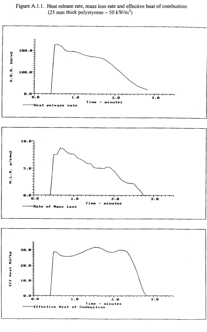
Initial Mass : 7.5 g Time of Peak RHR 35 s
Final Mass 0.0 g Peak REfR 228.4 kW/m2
Mass Lost 0.75 kg/m2 Peak Mass Loss 8.75 g/s*m2
Ignition Time : 27 s Peak Extinction Area: 1,130.03 m2/kg Flameout Time : 175 s Total Heat Released : 20.11 MJ/m2
Summary Data From Ignition
Test Mean 60s 180s 300s
Heat Release kw/m2 134.35 194.76 111.96 67.17
Mass Loss Rate g/s*m2 6.63 6.90 4.17 2.50
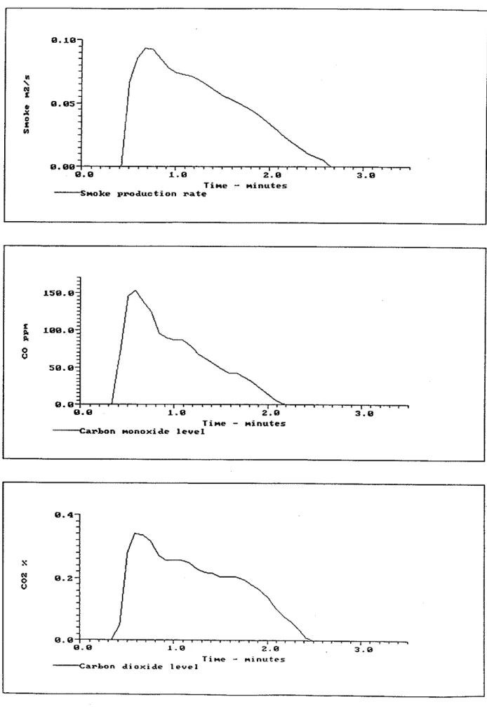
Heat of Combustion MJ/kg 26.81 28.22 26.87 26.87 Specific Ext. Area m2/kg 903.45 1,104.66 752.87 451.72 Carbon Dioxide 1.72573 1.65077 0.88853 0.53312 Carbon Monoxide kg/kg 0.03273 0.04887 0.02706 0.01624
OBSERVATIONS AND COMMENTS
Specimen melted to bottom of sample holder black smoke
Tested by : Seguin,Yves
Figure
A.1.1.
Heat release rate, massloss
rateand
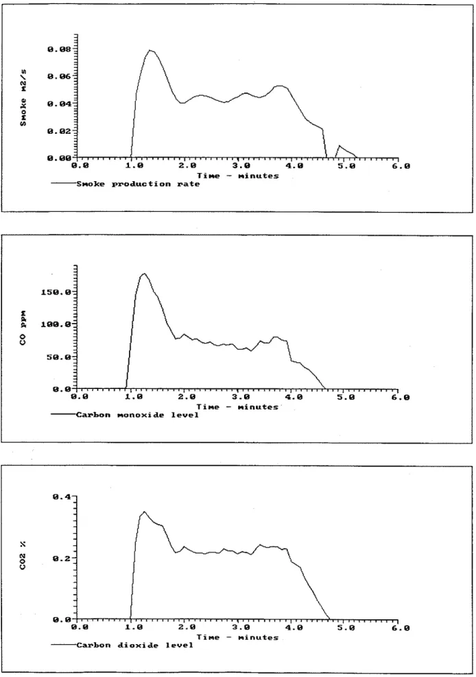
effective heat of combustionFigure A. 1.2. Smoke production rate, CO and CO2 concentrations (25
mm
thick polystyrene-
50 kw/m2) E. 10- b, \ N z p, 8 . 8 5 - xP
b3-
E.EE. . .
/. . .
1 5 8 . E l E E . E a 0 u 5 8 . 8 0 . 8 , E . E l . E 2 . 8 3 . 8 T i m e-
minutes-
S m o k e p ~ o d u c t i o n p a t e. . .
E.4--
-
.-
-
S-
N 0 . 2 -8
-
13.E 0. E 1 . 8 2 . 8 3 . 8 T i m e-
minutes ---Carbon monoxide level. . .
,
. . .
,
. . .
. ,
E . E 1 . E 2.W 3 . 8
T i n e
-
m x n u t e sSUMMARY TEST REPORT Cone Calorimeter
Test Ref: FOR25P05 Test Date: 11-29-1995
Date Received: 11-17-1995 DETAILS OF MATERIAL TESTED
Sponsor :
Forintek Canada Corp.
Material: 25
mm thick extruded polystyrene
DETAILS OF TEST PROCEDURE USED
Heat Flux : 75.0
kW/mz
Nominal Flow : 30 .Ol/s
Orifice Constant : 0.037156 Heat per Unit Mole : 13.10000
kJ/g02
Heater Orientation :
Horizontal
Spark Ignitor Used : YGrid Used :
N
Frame Used :Y
Conditioning : 50.0
RH
@ 23.0°C Test Conditions : 60.0RH
@ 25.E°CSpecimen Thickness: 0.025000m Specimen Area : 0.010000
m2
TEST RESULTS
Initial Mass : 7.6 g Time of Peak RHR 15
s
Final Mass 0.0 g Peak RHR 273.5
kW/m2
Mass Lost 0.76
kg/m2
Peak Mass Loss 11.81g/s*m2
Ignition Time : 10
s
Peak Extinction Area: 1,318.19m2/kg
Flameout Time : 133
s
Total Heat Released : 19.55MJ/m'
Summary Data From Ignition
Test Mean
60s 180s 300sHeat Release
kW/m
163.57 227.37 109.04 65.43Mass Loss Rate
g/s*m2
8.17 8.70 4.22 2.53Heat of Combustion MJ/kg
25.73 26.15 25.83 25.83Specific Ext. Area rn2/kg
1,018.28 1,132.45 678.85 407.31Carbon Dioxide
kg/kg
1.82100 1.78081 0.92137 0.55282Carbon Monoxide
kg/kg
0.03496 0.04437 0.02311 0.01386OBSERVATIONS AND COMMENTS
Specimen melted to bottom of sample holder
black smoke
Tested
by
:Seguin,Yves
Figure A. 1.3. Heat release fate, mass loss rate and effective heat of combustion
(25
mm thick polystyrene-
75 k w h 2 ) 388.8 N I \ 2 8 8 . 85
i
i
m a . 8 I 8 . a , s . 3 . . ~ . , . , . . , , . . ~ , , , . . , , , 8 . 8 1 . 8 2 . 8 T i n e-
m i n u t e s n e a t pelease -ate-
Figure A. 1.4. Smoke production rate, CO and C02 concentrations
Appendix A2
-
LIFT Test Results for 25 rnrn Thick Extruded PolystyreneTests were conducted according to ASTM E l 321
-
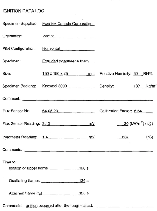
90 [21.]. A sample data logging form showing the test conditions is provided in Table A2.1. The ignition test results are given in Figures A2.1 through A2.3 and Table A2.2.During the ignition tests, the polystyrene specimens almost completely melted before ignition. The ignition times reported are when flame attachment to the melted polystyrene on the holder was observed. For easily melting materials, the time to ignition is a strong function of the specimen holder and its orientation. If the holder allows for drainage of liquid from the bottom, flame attachment is unlikely due to lack of combustible material on the specimen holder. Conversely, a slight inclination of the sample holder towards the end with the higher-heat-flux can result in an earlier ignition of the material.
Flame spread data showed inconsistent results. The polystyrene specimen melted and accumulated at the bottom of the sample holder before ignition and flame attachment occurred. Because of the inconsistency in the results, they are not reproduced in this report.
Table
A2.1.
Sample ignition data logfor
25mm
thick extruded polystyrene foam.IGNITION
DATA
LOGSpecimen Supplier: Forintek Canada Corooration
Orientation: Vertical
Pilot Configuration: Horizontal
Specimen: Extruded oolvstvrene foam
Size: 1 5 0 x 1 5 0 ~ 2 5 mm Relative Humidity: L R H %
Specimen Backing: Kaowool3000 Density: 187 kg/m3
Comment:
Flux Sensor No: 64-05-20 Calibration Factor: 6.64
Flux Sensor Reading: 3.12 mV
2
(kwlm2)(a,)
Pyrometer Reading: 1.4 mV
637
2-'"(Comments: Time to:
Ignition of upper flame 126 s
Oscillating flames 126 s
Attached flame (tig) 126 s
thick polystyrene foam.
Parameter Result
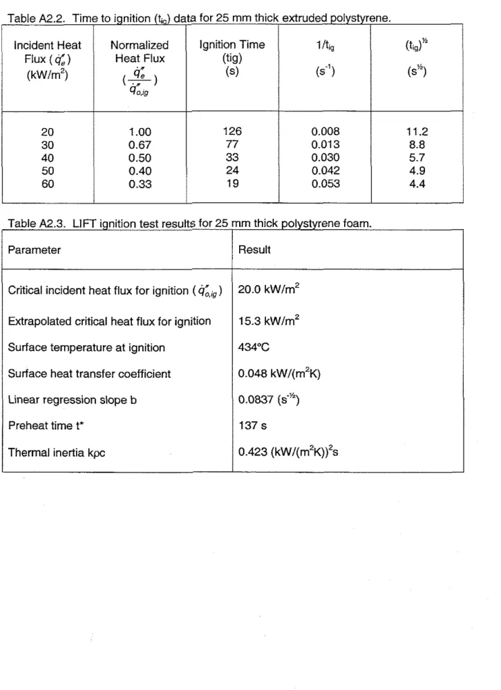
Table A2.2. Time to ignition (t,) data for 25 mm thick extruded polystyrene.
Surface temperature at ignition Surface heat transfer coefficient Linear regression slope b
Preheat time t' Thermal inertia kpc Incident Heat Flux
( 4 )
( k w h 2 ) 20 30 40 50 60Critical incident heat flux for ignition (cj;,,) Extrapolated critical heat flux for ignition
I /tiQ
6')
0.008 0.01 3 0.030 0.042 0.053 20.0 kw/rn2 15.3 kw/m2 (tig)" (ss) 1 1.2 8.8 5.7 4.9 4.4 Normalized Heat Flux cj; ( 7 )40.~~
1 .OO 0.67 0.50 0.40 0.33 Ignition Time (tig) (s) 126 77 33 24 19Incident heat flux (kw/rn2)
Experimental results
Linear regression b = 0.0837
.
30 40 50 Incident Heat Flux (kw/rn2) Figure A2.3. Ilt,, versus incident heat flux.
Appendix A3
-
ASTM Full-Scale Room Corner Fire Test Results for 25 mm Thick Extruded PolystyreneA full-scale room corner test was conducted for the 25 mm thick extruded oolvstvrene usina
..
the proposed ASTM procedure [3]. The polystyrene was glued to 12.5 m; t $ c C ~ ~ p e XAppendix
B
-Test Results for 50m m
Thick Extruded PolystyreneAppendix B provides the results of the cone calorimeter, LlFT and full-scale roodcorner tests with 50 mm thick extruded polystyrene. The results of the tests are provided in the following sections:
B1
-
Cone Calorimeter Test Results for 50 rnm Thick Extruded Polystyrene82
-
LlFT Test Results for 50 mm Thick Extruded Polystyrene83
-
ASTM Full-Scale Room Corner Fire Test Results for 50 mm Thick ExtrudedPolystyrene
Appendix
B1
-Cone Calorimeter Test Results for 50 mm Thick Extruded Polystyrene Tests were conducted according to ASTM E 1354 [I]. For these tests, the data collection was continued beyond flame extinction. Tests were conducted with the following heating fluxes: 25 kw/rn2 (no ignition), 50 kw/rn2 and 75 kw/rn2. The specimen did not ignite with the 25 k w h 2 exposure and no data is provided.Test Ref: FOR50P02
SUMMARY TEST REPORT Cone Calorimeter
Test Date: 11-29-1995 Date Received: 11-17-1995
DETAILS OF MATERIAL TESTED
Sponsor : Forintek Canada Corp.
Material: 50 mm thick extruded polystyrene
DETAILS OF TEST PROCEDURE USED
Heat Flux : 50.0 kW/m2 Nominal Flow : 30.0
l/s
Orifice Constant : 0.037156 Heat per Unit Mole : 13.10000 kJ/g02 Heater Orientation : Horizontal Spark Ignitor Used :
Y
Grid Used :
N
Frame Used :Y
Conditioning : 50.0
RH
@ 23.0°C Test Conditions : 60.0RH
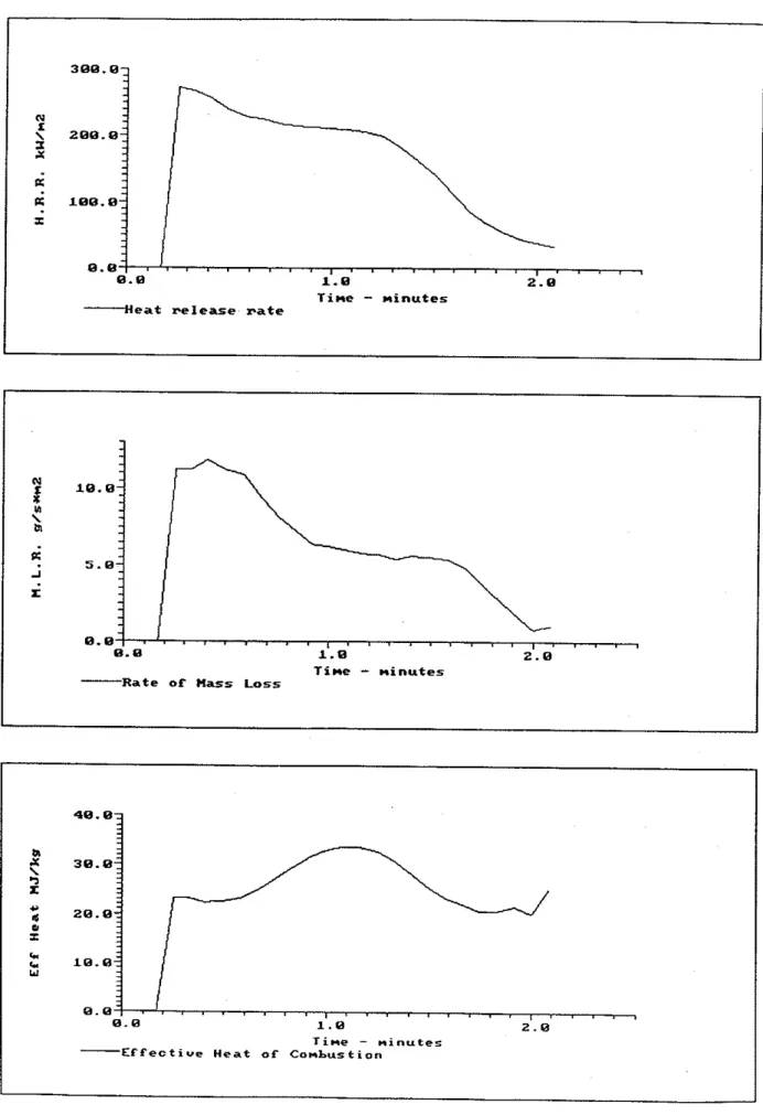
@ 27.6"C Specimen Thickness: 0.050000m Specimen Area : 0.010000 m2 TEST RESULTSInitial Mass : 14.6 g Time of Peak RHR 70 s
Final Mass 0.0 g Peak RHR 243.5 kW/m2
Mass Lost 1.46 kg/m2 Peak Mass Loss 12.27 g/s*m2
Ignition Time : 63
s
Peak Extinction Area: 2,035.17 m2/kg Flameout Time : 320 s Total Heat Released : 42.57 MJ/m2 Summary Data From IgnitionTest Mean 605 180s 300s
Heat Release kW/m2 163.94 211.87 200.11 142.08
Mass Loss Rate g/s*m2 6.60 8.19 6.67 4.87
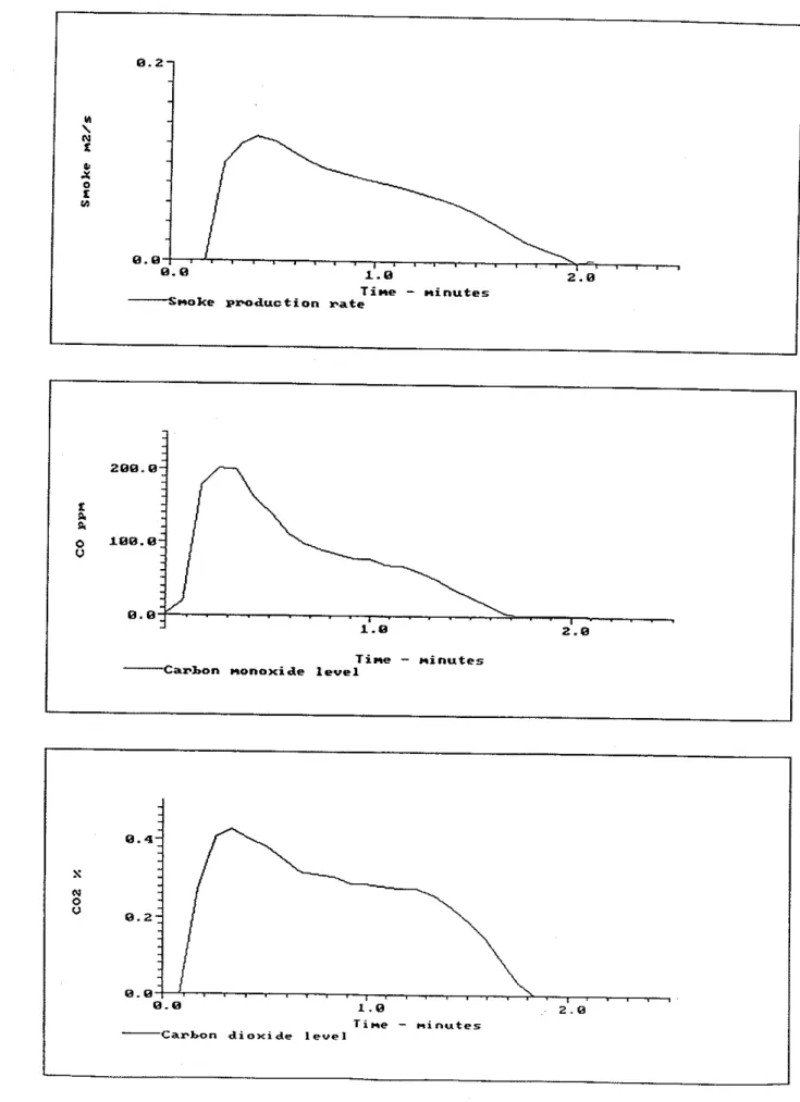
Heat of Combustion MJ/kg 29.16 25.86 30.00 29.19 Specific Ext. Area m2/kg 710.80 719.41 751.05 616.03 Carbon Dioxide kg/kg 1.72009 1.39612 1.28963 0.91915 Carbon Monoxide kg/kg 0.03865 0.05162 0.04413 0.03336
OBSERVATIONS AND COMMENTS
Specimen melted to bottom of sample holder black smoke
Tested by : Seguin,Yves
Figure
B.
1.1. Heat release rate, mass loss rate and effective heat of combustion (50 mm thick polystyrene - 50kw/m2)
Time-
minutes H e a t release Fate-
-
-
-
-
i
+ B . B {<
ba-
-
.i
-I 5.0;-
E-
-
-
8 . 8. . .
. . .
78.8 6 8 . 8 ba 5 8 . 8 9 z Y 4 8 . 8 6 ffi 38.8 I C 2 8 . 8 C Y 1 8 . 8 8 . 8 8 . 8 1 . 8 2 . 8 3 . 8 4 . 8 5 . 8 6 . 8 Tine - minutes -Rate of Mass LossI B I . . I . I ~ . I I . . .
. . .
8 . 8 1 . 8 2 . 8 3 . 8 4 . 8 5 . 8 6 . 8
Time
-
minutes E f f e c t i v e Heat of Corbus tionFigure
B. 1.2.
Smoke production rate, CO and C 0 2 concentrations (50rnm
thick polystyrene -50
kw/m2) T i m e-
m i n u t e s S m o k e p r o d u c t i o n r a t eI
T i m e-
minutes C a r b o n m o n o x i d e levelI
8 . 4 --
S-
N 0 8 . 2 - 0-
-
-
-
-
-
8 . 8 S I . . . I I . G E . . . S Z . . . B ...7~ maa..a..II IIII .III I...~ 8 . 8 1 . 8 2 . 8 3 . 8 4 . 8 5 . 8 6 . 8 T x m e - mxnutes -Carbon d i o x ~ d e level-
SUl@V&Y TEST REPORT Cone Calorimeter
Test Ref: FOR50P05 Test Date: 11-29-1995
Date Received: 11-17-1995 DETAILS OF MATERIAL TESTED
Sponsor : Forintek Canada Corp
Material: 50 mm thick extruded polystyrene
DETAILS OF TEST PROCEDURE USED
Heat Flux : 75.0 kW/m2 Nominal Flow : 30.0 l/s
Orifice Constant : 0.037156 Heat per Unit Mole : 13.10000 kJ/gOZ
Heater Orientation : Horizontal Spark Ignitor Used : Y
Grid Used :
N
Frame Used :Y
Conditioning : 50.0 RH @ 23.0°C Test Conditions : 60.0 RH @ 26.3OC
Specimen Thickness: 0.050000m Specimen Area : 0.010000 m 2
TEST RESULTS
Initial Mass : 14.6 g Time of Peak RHR 25 s
Final Mass 0.0 g Peak RHR 240.9 kW/m2
Mass Lost 1.46 kg/m2 Peak Mass Loss 22.63 g/s*m2
Ignition Time : 15 s Peak Extinction Area: 3,230.31 m2/kg
Flameout Time : 221 s Total Heat Released : 35.64 MJ/m2 Sununary Data From Ignition
Test Mean 60s 180s 300s
Heat Release kW/m2 173.93 218.16 192.16 118.85
Mass Loss Rate g/s*m2 7.67 8.64 7.76 4.87
Heat of Combustion MJ/kg 24.41 25.25 24.77 24.42 Specific Ext. Area m2/kg 819.78 767.32 838.74 560.18 Carbon Dioxide kg/kg 1.75764 1.78494 1.57579 1.03004 Carbon Monoxide kg/kg 0.04088 0.05015 0.04221 0.02790
OBSERVATIONS AND COMMENTS
Specimen melted to bottom of sample holder black smoke
Tested by : Seguin,Yves
Figure
B.1.3.
Heat release rate, mass loss rate and effective heat of combustion(50
mm
thick polystyrene-
75 k w h 2 ) 388.03-
. . N-
-
I-
\ 2ee.e: x . x-
-
-
-
K-
-
K Lee.8:-
I-
8 . 8. . .
~ ~ ~ . . i s . I . I . . . I 8.8 1.8 2.8 3.8 4.8 T i m e - minutes H e a t r e l e a s e F a t e 78.8 68.8 01?
58.8 s C 48.8 6 U 38.8 I C 28.8 C w 8.8 L.8 2.8 3.8 4. 8 T i m e-
minutes E f f e c t i v e Heat of C o m b u s t i o n 28.8 UI \ 01'!
18.8 -Ir:
@.@,I 7. . .
. . . I 8.8 1.8 2.8 3.9 4.8 T i m e - minutes-
R a t e o f Mass LossFigure B.
1.4.Smoke
production rate,CO
andC02
concentrations (50mm
thick polystyrene-
75kw/m2)
--
299.8--
z-
e.-
$
1ee.9-j . 9 . 9 , .. . .
. .
.
,.
,
.
. ,. . . . .
.
,
.
, , , ,.
, , ,,
, , , , ,. . .
9.8 1.9 2.9 3.8 4.9 T i m e - m i n u t e s C a r h o n nonoxide l e v e l 8.4- S-
g
9.2- u-
8.8 . , . . s . . . , , . . , 9 , , , , , , , , , , , , , 3 , , , , , , , , ~ , ~ 8.8 L.8 2.9 3.9 4.8 T i m e-
m i n u t e s C a r b o n d i o x i d e l e v e lAppendix
82
-
LIFT Test Results for 50rnm
Thick Extruded PolystyreneThe behavior of 50 mm extruded specimens was similar to the 25 mm thick specimens
(Appendix A2). During the preliminary ignition tests, the polystyrene specimens almost completely melted before ignition. It was apparent that the test results for polystyrene foam were dependent on the specimen holder and its orientation. If the holder allowed for
drainage of liquid from the bottom, flame attachment was unlikely due to lack of combustible material on the specimen holder. It was decided that the LIFT test results of polystyrene would prove to be of little scientific value and the tests were not continued.
Appendix
63
-
ASTM Full-Scale Room Corner Fire Test Results for 50 mmThick
Extruded Polystyrene
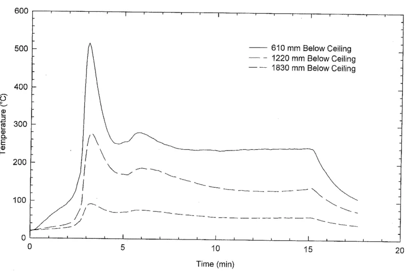
A full-scale room corner test was conducted for the 50 mm thick extruded polystyrene using the proposed ASTM procedure [3]. The polystyrene was glued to 12.5 mm thick Type X
600 I I I 500 - --- 610 mm Below Ceiling
-
-
- 1220 mm Below Ceil~ng--
1830 mm Below Ceil~ng 400-
0
--
300 - a, -E"
?
-L J - y
'--.
1----_--
-'
'---
- _
----_---
--.
--
'.
0 I I I 0 5 10 15 20 Time (min)Appendix B4
-
IS0 Full-Scale Room Corner Fire Test Results for 50 mm ThickExtruded Polystyrene
A full-scale room corner test was conducted for the 50 mrn thick extruded polystyrene using the I S 0 9705 test procedure 141. The polystyrene was glued to 12.5 mm thick Type X
5
Time (min)
5 Time (min)
Time (min)
Appendix C -Test Results for 12.5
m m
Thick Oak-Veneered PlywoodAppendix C provides the results of the cone calorimeter, LlFT and full-scale roorn/corner tests with 12.5 rnrn thick oak-veneered plywood. The results of the tests are provided in the following sections:
C1
-
Cone Calorimeter Test Results for 12.5 rnrn Thick Oak-Veneered PlywoodC2
-
LlFT Test Results for 12.5mm
Thick Oak-Veneered PlywoodC3
-
ASTM Full-Scale Room Corner Fire Test Results for 12.5 rnrn Thick Oak-VeneeredPlywood
C4
-
I S 0 Full-Scale Room Corner Fire Test Results for 12.5 rnrn Thick Oak-VeneeredAppendix C1
-
Cone Calorimeter Test Results for 12.5 mm Thick Oak-Veneered PlywoodTests were conducted according to ASTM E 1354 [I]. For these tests, the data collection
was continued beyond flame extinction. Tests were conducted with the following heating fluxes: 25 kw/m2, 50 k w h 2 and 75 kw/m2. In addition, a test was also conducted by ORTECH using a heating flux of 50 kw/m2. A copy of the ORTECH test report is included in Appendix C1 (ORTECH report number 96-J52-95-4-40(C).
Test Ref: FOROVOl
SUMMARY TEST REPORT Cone Calorimeter
Test Date: 12-04-1995 Date Received: 11-17-1995
DETAILS OF MATERIAL TESTED Sponsor :
Forintek Canada Corp
Material: 12.5
mm thick oak veneered plywood
DETAILS OF TEST PROCEDURE USED
Heat Flux : 25.0
kW/m2
Nominal Flow : 30.0l/s
Orifice Constant : 0.037067 Heat per Unit Mole : 13.10000
kJ/g02
Heater Orientation :
Horizontal
Spark Ignitor Used : YGrid Used :
N
Frame Used :Y
Conditioning : 50.0 RH @ 23.0°C Test Conditions : 60.0 RH @ 27.6OC
Specimen Thickness: 0.012800m Specimen Area : 0.010000
m2
TEST RESULTS
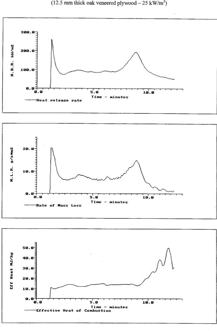
Initial Mass : 63.8
g
Time of Peak RHR : 75s
Final Mass 15.7
g
Peak RHR : 260.7kW/m2
Mass Lost 4.81
kg/m2
Peak Mass Loss : 20.33g/s*m2
Ignition Time : 73
s
Peak Extinction Area: 163.54m2/kg
Flameout Time : 743
s
Total Heat Released : 66.96MJ/m2
Summary Data From Ignition
Test Mean
60s 180s 300sHeat Release
kW/m2
100.13 125.38 100.36 95.55Mass Loss Rate
g/s*m2
8.17 12.25 8.89 7.92Heat
of Combustion MJ/kg
13.91 10.24 11.29 12.06Specific Ext. Area m2/kg
82.62 97.49 79.91 78.17Carbon Dioxide
kg/kg
1.07620 0.53451 0.78751 0.87634Carbon Monoxide
kg/kg
0.00364 0.00000 0.00000 0.00000OBSERVATIONS AND COMMENTS
Good run.
Tested by :
Seguin,Yves
Figure C.l . I . Heat release rate, mass loss rate and effective heat of combustion
(12.5
rnm thick oak veneered plywood
-
25 kw/mz)
5 8 . 8 a 48.8
2
+, 3 8 . 8t
2 6 . 8 C C 18.8 ~ . e , . . . . , . ~ . . , . . , . , . . . . , . , . . . . 0 . 0 5 . 8 18. 8 T i m e-
m i n u t e s - V f e ~ t i u e Heat o f C o m b u s t i o nT i m e
-
m i n u t e s S m o k e production rate 88.8 68.8 C e, 48.8 0 u 28.8 8 . 8 , .. . . , . . . - . ,
5 . 8 18.8 T i n e-
m i n u t e s - C a r b o n m o n o x i d e l e v e l 8.6 I S 8 . 4 8.2 8 . 8 5 . 8 18. 8 T i r e-
m i n u t e s F r b o n dioxide l e v e lSUMMARY TEST REPORT Cone Calorimeter
Test Ref:
FOROV03
Test Date: 12-04-1995Date Received: 11-17-1995 DETAILS OF MATERIAL TESTED
Sponsor :
Forintek Canada Corp.
Material: 12.5mm
thick oak veneered plywood
DETAILS OF TEST PROCEDURE USED
Heat Flux : 50.0
kW/m2
Nominal Flow : 30.0l/s
Orifice Constant : 0.037067 Heat per Unit Mole : 13.10000
kJ/g02
Heater Orientation :
Horizontal
Spark Ignitor Used :Y
Grid Used :
N
Frame Used :Y
Conditioning : 50.0 RH @ 23.0°C Test Conditions : 60.0 RH @ 26.6OC
Specimen Thickness: 0.012800m Specimen Area : 0.010000
m 2
TEST RESULTS
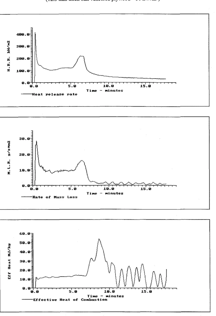
Initial Mass : 62.7 g Time of Peak RHR 20
s
Final Mass 6.8
g
Peak RHR 412.9kW/m2
Mass Lost 5.59
kg/m2
Peak Mass Loss 28.28g/s*m2
Ignition Time : 16
s
Peak Extinction Area: 328.48m2/kg
Flameout Time : 1,067
s
Total Heat Released : 86.06MJ/m2
Summary Data From Ignition
Test Mean
60s 180s 300sHeat Release
kW/m2
82.04 179.36 131.35 125.78Mass Loss Rate
g/s*m2
8.83 17.39 11.49 10.72Heat of Combustion MJ/kg
15.40 10.31 11.43 11.73Specific
E x t .Area mz/kg
107.33 113.29 99.92 89.65Carbon Dioxide
kg/kg
0.89792 0.67024 0.76451 0.81953Carbon Monoxide
kg/kg
0.04764 -0.00000 -0.00000 -0.00000OBSERVATIONS
AND
COMMENTSFlameout difficult to estimate
Tested by :
Seguin,Yves
Figure C.1.3. Heat release rate, mass loss rate and effective heat of combustion
(12.5 rnm thick oak veneered plywood
-50 kw/m2)
38.8
i
29.8 e; -Ii
10.9 8 . 8 , . ,. . .
8.8 5.8 18.8 15.8 T i n e-
m i n u t e s -Rate o f Mass Loss488.8 N L 388.8 I x 289.8
e:
1ee.e 8 . 8 . ~ . 68.8 58.8$
49.8 r 39.8 8 I 29.8 6, 6, 18.8 8.8 8.8 5.8 18.8 15.8 T i n e-
m i n u t e s - E f f e c t i v e H e a t o f Combustion. . .
8. 9 5.8 18.8 15.8 Time-
m i n u t e s H e a t r e l e a s e r a t eFigure C. 1.4. Smoke production rate, CO and CO2 concentrations
(12.5
mm
thickoak veneered plywood
-50 kw/m2)
8.84-
-
. u . \ N L 0.82-!
L W 8.88- - . ? 8 . 9 5 . 8 18.8 15.8 T i m e-
m i n u t e s --Smoke production Fate158.8 188.8 PI 0 u 5 8 . 8 B . B , . ! . . . . . . . , ~ ~ ~ ~ ~ . ~ . . , . . . . ~ . . ~ ~ I ~ ~ ~ ~ ~ ~ . '
-
t . 8 --
S-
-
3
8.5--
8. 8 5 . 9 18.8 1 5 . 8 T i n e-
m i n u t e s ----Carbon monoxide l e v e l I 8 . 8 5 . 8 18.8 15.8 T i m e-
m i n u t e s ----Carbon d i o x i d e l e v e lSllMMARY TEST REPORT Cone Calorimeter
Test Ref: FOROV06 Test Date: 12-04-1995
Date Received: 11-17-1995
DETAILS OF MATERIAL TESTED
Sponsor : Forintek Canada Corp.
Material: 12.5 mm thick oak veneered plywood
DETAILS OF TEST PROCEDURE USED
Heat Flux : 75.0 kW/m2 Nominal Flow : 30.0 l/s
Orifice Constant : 0.037067 Heat per Unit Mole : 13.10000 kJ/g02
Heater Orientation : Horizontal Spark Ignitor Used : Y
Grid Used :
N
Frame Used :Y
Conditioning : 50.0 RH @ 23.0°C Test Conditions : 60.0 RH @ 25.g°C
Specimen Thickness: 0.012800m Specimen Area : 0.010000 m2
TEST RESULTS
Initial Mass : 65.0 g Time of Peak RHR 15 s
Final Mass 1.2 g Peak RHR 459.1 kW/m2
Mass Lost 6.38 kg/m2 Peak Mass Loss 32.29 g/s*m2
Ignition Time : 12 s Peak Extinction Area: 346.08 m2/kg
Flameout Time : 1,653
s
Total Heat Released : 113.92 MJ/m2Summary Data From Ignition
Test Mean 60s 180s 300s
Heat Release kW/m2 69.49 211.07 164.57 166.03 Mass Loss Rate g/s*m2 6.24 20.07 14.78 13.81 Heat of Combustion MJ/kg 17.85 10.52 11.13 12.02 Specific Ext. Area m2/kg 164.58 131.77 126.12 126.94 Carbon Dioxide kg/kg 0.85644 0.81751 0.86255 0.98026 Carbon Monoxide kg/kg 0.17277 0.00000 0.00000 -0.00000
OBSERVATIONS AND COMMENTS
Flameout difficult to estimate.
Tested by : Seguin,Yves
Figure C.1.5. Heat release rate, mass loss rate and effective heat of combustion
(12.5
mm thick
oakveneered plywood
- 75kw/m2)
3 8 . 8
$
2 8 . 8K
-1i
'%-%-!
+-.
$ 8 , 8 . 8 1 8 . 8 2 8 . 8 3 8 . 8 T i m e-
minutes R a t e o f l a s s Loss 5 8 8 . 8 N 4 8 8 . 8 L \ 3 8 8 . 8K
288.8K
I 1 8 8 . 8 5 8 . 8 t? 4 8 . 8 5 r 3 8 . 82
=
2 8 . 8 C C w 1 8 . E 8 . 8 8 . 8 1 8 . 8 2 8 . 8 3 8 . 8 T i m e-
minutes -Effective Heat o f Combustion8 . 8 1 a 1 1 . 1 . 1 . . 1 1 1 . . 1 . . 1 1 1 1 1 . 1 . . 1 . 1 ,
8 . 8 1 s . E 2 8 . 8 3 8 . 8
T i m e
-
minutes -Heat r e l e a s e r a t eFigure C. 1.6. Smoke production rate, CO and COz concentrations
(12.5 mm thick oak veneered plywood
-
75 kwim2)
8.84-
-
-
-
.t
. . N . I . 8.82-9
-
0-
I-
V)-
-
-
. . 8.88 a I I I I I 4 , - , , fl , , ,jI
,A , , , 8.8 18.8 28.8 38.8 Time-
minutes -make production rateTire
-
minutesI
-
CaFbon monoxide level
-
L.8: S N8
-
1 1 , 1 1 1 1 1. . . . ,
, , , . , , , , . , 8.8 18.8 28.8 38.8 Time-
minutes -arbon dioxide levelORTECH
ASTM E 1354 Heat and Visible Smoke Release Rates of Plywood Page 1 of 6 For: National Research Council Canada Report No. 96-J52-95-4-40(C)
ACCREDITATION
Standards Council of Canada. Registration #1BREGlSTRATlON
I S 0 9002-1994, registered by QMI, Registration #001109,SPECIFICATIONS OF ORDFR
Perform single determination in accordance with ASTM
E
1354-
Standard Test Method for Heat and Visible Smoke Release Rates for Materials and Products Using an Oxygen Consumption Calorimeter, at a radiant heat flux of 50 kW/mz, as per your letter dated January 19, 1996.lDENTlFlCATlON
Sample C: Plywood.
(ORTECH sample identification number 96-J52-S0040-3)
SUMMARY
OF
TEST PROCEDURF
Three specimens, 100 mm x 100 mm in size, are conditioned to equilibrium at 50 i 5%
relative humidity and
23
i 3°C before testing.Each specimen is mounted into a holder and placed horizontally below a cone-shaped radiant heat source which has been previously set to emit a specified heat flux. A spark source is located 13 mm above the surface of the specimen in order to promote ignition in ambient air conditions, while a load cell continuously monitors specimen mass loss.
Exhaust gas flow rate and oxygen concentration are used to determine the amount of heat release, based on the observation that the net heat of combustion is directly related to the amount of oxygen required for combustion. The relationship is that approximately 13,100 kJ of heat are released
pei
1 kg of oxygen consumed.In addition to rate of heat release, other measurements include mass-loss rate, time to sustained flaming and smoke obscuration.
OBSERVATIONS
Following ignition at 15 seconds, the material flamed until, by the 15 minute point, only a small amount of surface flaming continued. This dimished to flickering within the surface cracks at 25 minutes, followed by surface glowing up to extinguishment at 33 minutes
w~&~*
H.J. ampbell. Ph.D.,
ire'&
Flammability, Materials Validation.Manager,
ORTECH
ASTM E 1354 Heat and Visible Smoke Release Rates of Plywood Page 2 of 6 For: National Research Council Canada Report No. 96-J52-95-4-40(C)
Heat and Visible Smoke Release Rates for Materials and Products
H ~ - ~ ~ L F ! u x ~
.50kW!.~!f
Exhagst Flow Rate: 24.0 UsSpecimen Thickness (rnrn) 12.0 ; . . . . . . - - 3
i
Initial Mass (g) 51.7;
!
. . . ...; -
1
Final Mass (g) ; 1.2j
...--
-
i
: Mass Loss (kglm2) 5.05 i .-
. . .I
Peak Mass Loss Rate (gls.m2) 13.17i
. . . .
... . .
I
Average Mass Loss Rate (gls.rn2) 3.69... . . .
,
.... ...--
/
Time to Ignition (s) 15/
I .1
Time to Flame-out (s):
19801
I i:
Time of Peak Rate of Heat Release (s)i
4151
~-
. ... ...- ...
Peak Rate of Heat Release (kWlm2) 150.6 i
...
.. ~
Average Rate of Heat Release (kWlmz) 37.82
. . . . . . .. .--A
Total Heat Released (MJlm2) 74.28
i . . . . I
j
Av. Effective Heat of Combustion (MJlkg) ; 14.701
~~~ -
: Peak Extinction Area (m2/kg) '1060.8
1
... . - - . - - . - - L
Average Extinction Area (m2/kg) 145.04
ORTECH
ASTM
E
1354 Heat and Visible Smoke Release Rates of Plywood Page 3 of 6 For: National Research Council Canada Report No. 96-J52-95-4-40(C)TFST RESULTS
[Contd
10 15 20 25
TIME (minutes)
. . . ~ ~. ~. .
Peak Rate of Heat Release (kW/m2) 150.6
-~
~ ~ . -. ~ - . -.Average Heat Release Rate (kW/mz)'
37.82
-
-
. . . - . .. - --- - .I
7
:
Heat Release Rate @ 60 s (kW/m2)** j108.65i
----
I
Heat Release Rate @ 180 s (kW/m2)^' 82.74
. - ~ ~ ~ ~.. . . . . . .
Heat Release Rate @ 300 s (kW/m2)" 76.77
ORTECH
ASTM
E
1354 Heat and Visible Smoke Release Rates of Plywood Page 4 of 6For:
National Research Council Canada Report No. 96-J52-95-4-40(C)EFFECTIVE HEAT OF COMBUSTION
I
10 15 20 25
TIME (minutes)
Average Heat of Combustion (MJlkg)' 14.70
/
L
... 2;
Heat of Combustion@
60 s (MJlkg)" 111.94 1~-
i ... ..---
j
Heat of Combustion @ 180s
(MJlkg)" 10.25!
. . - - . - . . . . --.--...-...-.. ..:
Heat of Combustion @ 300 s (MJlkg)" 10.07 : . . . - . . . . ... - ...* Avcr;~?c.J ova- the ~ r t ~ i t r l slaninp u h c n 10% al'tht t ~ l i ~ n a t t ninsr loss occun-ed and
C I I ~ I I I I ~ :I! tltc I I I I I ~ IIIICII 9 i l ' X 8 c>i!I>t ~tItiln:~tc III:ISS IOSS L K C ~ I I T C ~
+ *
AICI-:I;CLI 13vcr !he 60. I S 0 .ilKl x c c , ~ ~ d )icn<xJ.r stanin&! ~ v h c n 10??1 ofthc ultimateORTECH
ASTM E 1354 Heat and Visible Smoke Release Rates of Plywood Page 5 of 6 For: National Research Council Canada Report No. 96-J52-95-4-40(C)
SMOKE
OBSCURATION
1
i
10 15 20 25
TIME (minutes)
r ~~ ..
-
!
Peak Extinction Area (rn2/kg)! 11060.8
/
-
---
-. --
-
---- - - . ..-
-. . ---t---:;
Average Extinction Area (rn2/kg)'!
145.01
-
-
. -- -- . .- I1
Extinction Area @ 60s
(mz/kg)";
150.6 ~. - . ...1
Extinction Area @ 180 s (m2/kg)** $00.1 ~ ~~. .. . ~~~. . . ~. ~. Extinction Area @ 300 s (m2/kg)^' 74.4 - - .. . . .. ~ ~ . . -. . . - . .. -.---
-ORTECH
ASTM
E1354 Heat and Visible Smoke Release Rates of Plywood
Page 6 of
6For: National Research Council Canada
Report No. 96-J52-95-4-40(C)
JEST RESULTS (C0nt.J
10
15
20
25
TIME (minutes)
-
.. - .~... ... . -r--
Peak Mass Loss Rate (gls-m2)
i 13.17
i
-. -. ~
-
.~+----
Average Mass Loss Rate (gls.rn2)'
:
3.69
j
~ . . ~. ~ -.----.-
:
Mass Loss Rate
@60 s (gls.m2)"
1
9.10
:
Mass Loss Rate @ 180
S(gls.rn2)"
!
' 8.07
1!
'
Mass Loss Rate
@300 s (gls.m2)"
7.62
!
-
- -- -. - - . . . -. .-- -
. ..- -
. .--
*
A\elagcd cncl. 1llc 1pc1-ioL1 sla1111lf !vlic~) I OUL, oilhe ulimalo m a s loss occwed and cnding :I( the lime \\l~cn ')U'K, oillie ullimare m:l.;s loss w u n - d**
A\-cr.;~gcd o\c.r I ~ I C 60. I SO tr- .;(I0 c c o n d i<eriods n;i~-Ling \vhcn 10% of the ultimate n1;tsi loss c ~ c ~ l n - c d .Appendix C2
-
LIFT Test Results for 12.5 mrn ThickOak
Veneered PlywoodTests were conducted according to ASTM
El321
-
90[2].
A
sample data logging formshowing the test conditions is provided in Table
C2.1.
The ignition test results are given in FiguresC2.1
throughC2.3
and TableC2.2.
The results for the flame spread tests with the3
specimens are provided in TablesC2.3
throughC2.5
and the flame spread data isTable
C2.1.
Sample ignition data log for12.5
mm thick oak-veneered plywood. IGNITION DATA LOGSpecimen Supplier: Forintek Canada Cor~oration
Orientation: Vertical
Pilot Configuration: Horizontal
Specimen: Oak veneered ~lvwood
Size: 150 x 150 x 12.5 mrn Relative Humidity: L R H %
Specimen Backing: Kaowool3000 Density: 187 kg/rn3
Comment:
Flux Sensor No: 64-05-20 Calibration Factor: 6.64
Flux Sensor Reading: 2.20 mV
3
(kwlm2) (<)Pyrometer Reading: 1.05 rnV
579
PC)Comments: Time to:
Ignition of upper flame 1037 s
Oscillating flames 1038 s
Attached flame (t,,) 1038 s
Table C2.2. Time to i
I
Table C2.3. LIFT ignition test results for 12.5 mm thick oak-veneered plywood.
I
I
Incident Heat
Flux
( G )
( k w h 2 )
Parameter
1
ResultCritical incident heat flux for ignition (q:,,)
Extrapolated critical heat flux for ignition Surface temperature at ignition
Surface heat transfer coefficient Linear regression slope b
Preheat time t' Thermal inertia kpc Normalized Heat Flux
s:
(7) 'I,, Ignition Time (tig) (s) I Itis 6 ' ) (tig)' (sYI)Table C2.4. Flame spread results
I
I
I
DistanceI
Time; for Test 1 (Incident flux at 50 rnm = 19 kw/rnz)
I I I
Table C2.5 Flame s read results for Test 2 lncide~
Distance Time
4:
. F(t) (kw/rn2)I_
Flame Front Velocity (V) ( m d s ) flux at 50 mm = 19 kw/m2) 1v - ~
(s'lrnm") Flame Front Velocity (V) ( m d s ) v-Y' (s"/rnm")Table C2.7. LIFT flame spread test results for 12.5 mm thick oak-veneered plywood.
I I I
Table C2.6 Flame spread results for Test 3 (Incident flux at 50 mm = 19 kw/mz)
/
parameter/
Result1
Distance imm) 250 275 300 325 350 375 400 425 450 475 500 520Flame spread parameter, C
1
4.43 m3s'/kwTime ( 9 1062 1079 1089 1096 1112 1130 1154 1180 1228 1278 1354 1440
Heat
flux
for ignition, minimumSurface temperature for ignition, minimum Heat flux for flame spread, minimum Temperature for flame spread, minimum
&
. F(t )
( k w h 2 ) 13.3 12.1 10.8 9.6 8.4 7.3 6.2 5.3 4.6 3.9 3.3 3.0 15.4 kw/m2 360°C 3.1 kw/rn2 95°CFlame heating parameter 43.0 KW2/m3
Flame Front Velocity (V) immfs) 1.8 2.9 2.1 1.5 1.2 1 .O 0.7 0.5 0.4 0.3 0.0 V-* (s*/mm") 0.74 0.59 0.70 0.83 0.92 1 .OO 1.23 1.40 1.60 1.90
Incident heat flux (kw/m2)
Figure C2.2. Normalized incident heat flux versus ti," 1.5 m ~ m a ~ m L m m r ~ L ~ 8 ~ ~ ~ r ~ , ~ ~ ~ ~ , ~ . ~ ~ , ~ ~ ~ ~ , m m m ~ , = ~ . ~ L . ~ ~ m Experimental results Linear regression b
=
0.0390 X 3 E-
F(t)
g
1 . 0 -a
-
K 0 N-
. , . ' * ~ m , ' , ~ . * ' m ~ ~ - ' l l l l 0 5 10 15 20 25 30 35 40 45 50 t, : (s")Incident Heat Flux (kw/m2) Figure C2.3. llt,, versus incident heat flux.
Appendix C3
-
ASTM Full-Scale Room Corner Fire Test Results for 12.5 mm Thick Oak-Veneered PlywoodA full-scale room corner test was conducted for the 12.5 rnm thick oak-veneered plywood
using the proposed ASTM procedure [3]. The oak-veneered plywood was attached to
12.5 mrn thick Type X gypsum board. The results of the tests are provided in Figures C3.1