Publisher’s version / Version de l'éditeur:
Vous avez des questions? Nous pouvons vous aider. Pour communiquer directement avec un auteur, consultez la première page de la revue dans laquelle son article a été publié afin de trouver ses coordonnées. Si vous n’arrivez pas à les repérer, communiquez avec nous à [email protected].
Questions? Contact the NRC Publications Archive team at
[email protected]. If you wish to email the authors directly, please see the first page of the publication for their contact information.
https://publications-cnrc.canada.ca/fra/droits
L’accès à ce site Web et l’utilisation de son contenu sont assujettis aux conditions présentées dans le site LISEZ CES CONDITIONS ATTENTIVEMENT AVANT D’UTILISER CE SITE WEB.
Proceedings of the International IMS Forum 2004: 17 May 2004, Lake Como, Italy, pp. 54-61, 2004-05-17
READ THESE TERMS AND CONDITIONS CAREFULLY BEFORE USING THIS WEBSITE. https://nrc-publications.canada.ca/eng/copyright
NRC Publications Archive Record / Notice des Archives des publications du CNRC : https://nrc-publications.canada.ca/eng/view/object/?id=94aef708-4ca5-4a39-8d54-3337c1f8c93a https://publications-cnrc.canada.ca/fra/voir/objet/?id=94aef708-4ca5-4a39-8d54-3337c1f8c93a
NRC Publications Archive
Archives des publications du CNRC
This publication could be one of several versions: author’s original, accepted manuscript or the publisher’s version. / La version de cette publication peut être l’une des suivantes : la version prépublication de l’auteur, la version acceptée du manuscrit ou la version de l’éditeur.
Access and use of this website and the material on it are subject to the Terms and Conditions set forth at Intelligent manufacturing and mold making
http://irc.nrc-cnrc.gc.ca
I n t e l l i g e n t m a n u f a c t u r i n g a n d m o l d m a k i n g
I M T I - X P - 2 9 2
S t r o u d , I . ; A h a m e d , S . S . ; N e e l a m k a v i l , J . ;
O s t o j i c , M .
A version of this document is published in / Une version de ce document se trouve dans: Proceedings of the International IMS Forum 2004, Lake Como, Italy, May 17, 2004, pp. 54-61
The material in this document is covered by the provisions of the Copyright Act, by Canadian laws, policies, regulations and international agreements. Such provisions serve to identify the information source and, in specific instances, to prohibit reproduction of materials without
written permission. For more information visit http://laws.justice.gc.ca/en/showtdm/cs/C-42
Les renseignements dans ce document sont protégés par la Loi sur le droit d'auteur, par les lois, les politiques et les règlements du Canada et des accords internationaux. Ces dispositions permettent d'identifier la source de l'information et, dans certains cas, d'interdire la copie de
Intelligent manufacturing and mold making
Ian Stroud 1, Syed Shafee Ahamed 2, Joseph Neelamkavil 2, Mile Ostojic 2
1
EPFL, STI-IPR-LICP, CH-1015 Lausanne, Switzerland [email protected]
2
National Research Council of Canada, Integrated Manufacturing Technologies Institute 800 Collip Circle, London, Ontario, Canada N6G 4X8
[email protected]; [email protected]; [email protected]
Abstract
This paper reviews the main problem areas specific to the mold manufacturing process and discusses how some of them can be addressed using intelligent manufacturing technologies. Networking of people, machines, and services is rapidly becoming strategic for cost-effective solutions and to share the resources and confined knowledge among individuals and organizations. Also products and processes today demand a wide domain of expertise. Concurrent engineering addressees these issues and creates a unified environment for groups of people to share their resources, core competencies and develop products much faster and cheaper and gain competitive advantage. The framework proposed consists of running high-end applications such as design, planning and analysis for the Mold and Die industries over the Internet. The designers should be able to communicate, share the knowledge and foresee any potential problems in downstream applications. Also the system provides a platform to simulate actual processes involved such as casting, flow, analysis and visualize the results over the internet and validate the requirements and specifications. The entire system is enriched by a knowledge engine which will provide advice on material selections, shrinkages, cavity layout, draft angles and cooling channels.
Keywords
Mold and die industry, collaborative working, integrated design and manufacturing.
1 Introduction
Mold making has some of the same problems as other manufacturing areas as well as its own specialities, which makes it a good candidate for intelligent manufacturing efforts. Some of these problems derive from the way that design is done; others depend on the manufacturing technology, as described below.
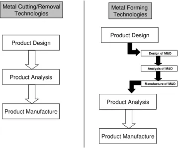
Design and manufacturing processes of products realized by material forming process such as molding, casting and stamping are more complex and multifaceted than products produced by metal cutting operations. Product produced by forming processes requires an additional cycle of design, analysis and manufacture of the Mold and Die (M&D) to produce the final components. The rational behind this being that the tools (like molds) required in the forming process have to be designed exclusively for the application, compared to commercially available tools that may be used directly for cutting/removal operations. Figure 1 illustrates the difference between the two processes.
Typically an automobile component produced by forming technologies such as molding, will require 6-8 months of cycle time to produce its mold and related tooling. Design data translations, lack of compatibility between systems in the design, analysis and manufacturing processes and physical prototyping are some of the major reasons for prolonged cycle time. Thus, it is believed that integration of these processes supported by simulation and knowledge driven advisory systems will help reduce the cycle time and automate the whole process.
Mold and die making activities require appropriate training and a high degree of skill. With the progress in CAD/CAM and CAE technologies the process of M&D making has improved and is now moving towards the next step of intelligent mold making. With the recent changes in the market trends and globalization, current M&D makers need to be more innovative and competitive. Thus there is a greater scope for new generation technologies to be adopted in M&D making. In a recent study conducted by CIM Data [CIM2001], it has been cited that the design related issues in M&D making account for nearly 20% of the total work. More than half of this time is spent in the detail design of the components. The manufacturing aspects of M&D also accounts for 20%. In this case most of the time is spent on the machining methods. The remaining 60% of the time is spent in activities such as planning, data transfer, fixture and tooling and other support activities. Based on the high concentration in the time for design and manufacture and the relationship with the support activities, it is believed that an integrated knowledge engineered design and manufacturing system would be appropriate for M&D making.
Metal Cutting/Removal
Technologies Metal Forming Technologies
Product Design Product Analysis Product Manufacture Product Design Product Analysis Product Manufacture Design of M&D Analysis of M&D Manufacture of M&D
Figure 1: Material Removal vs. Material Forming Manufacturing Process
2 Technological
aspects of the mold
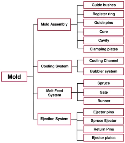
An injection mold is a mechanical assembly of many parts (a relatively complex mold could easily have 300 components) - some are product dependent; some are product independent. It includes a cavity system that consists of core, cavity, inserts and slider/lifter heads. An injection mold fulfills many other tasks such as the melt distribution, cooling of the melt, ejection of the molded product, guiding and aligning the mold halves. The structures and shapes of these items are somewhat independent of the product shape, but the size can be changed to suit the product. A mold base is a sub-assembly consisting of a group of plates, pins, guide bushes, etc. Ye et al [YFL2000] developed a generic structure for injection mold. The summary of major component systems associated with a typical injection mold as described in reference [MCH2001] is shown in Figure 2.
Stacking up several plates to form a rigid body creates a typical mold. Major components of a mold assembly are: core and cavity inserts that actually shapes the final product, register ring for location of mold with machine, guide pins and guide bushes for proper mold alignment, and clamping plates for mounting the mold.
The melt feed system channels the melt material from the injection nozzle into each cavity. It consists of a spruce to channel the flow, runners to evenly distribute the molten material, as well as gates as entry points to cavities. Coolants are circulated through the cooling system built into the mold, so as to remove the heat dissipated during the molding process.
After the molding material has been solidified and cooled down, an ejection system removes the product from its mold. Ejector pins and spruce ejector are used to eject the product and runner respectively, whereas return pins are used to push the ejector plate assembly back when the mold is closed.
Figure 2: Components in a Typical Injection Mold System
Traditionally, the design of an injection mold is done manually because of the high level of experience, empirical knowledge and expertise needed for the job. This is often tedious, time consuming and error-prone. The quality of the mold often dictates the economics of the molding process, though process control systems along with material properties also impact the outcome. Cycle times are determined primarily by the mold temperature control (cooling time).
The Initial stages of a mold design include selecting a suitable molding machine, deciding the number of cavities and arranging the cavity layout, determination of ejection direction and part-line location, designing gate and runner, and selecting a mold base. Detail design includes slider/lifter design, decisions on side core, ejectors layout, cooling and venting component design, analyzing mold parts for strength and final 3-D layout and drawing. These will benefit if they are embedded with knowledge enriched decision-making aids.
Mold Mold Assembly Cooling System Melt Feed System Ejection System Cooling Channel Bubbler system Spruce Gate Runner Ejector pins Spruce Ejector Return Pins Ejector plates Clamping plates Cavity Core Guide pins Register ring Guide bushes
2.1 Collaboration
The Mold and Die industry has become extremely competitive. There has been tremendous pressure on the M&D makers to reduce the time-to-market and cost of production. Global competition is demanding major changes and value added services. The technologies that add value to the process are all scattered around, and is beyond the core competencies of many mold makers. Outsourcing has become a common practice as companies have tried to reduce costs by specialising only in areas where they have special expertise. This has created opportunities for mold-making companies but, as in other areas, small and medium-sized companies have difficulty competing for large orders.
In this scenario, sharing information and data with team members, collaboration among applications such as design, simulation and manufacture, and timely participation in product development by all stakeholders can help reduce lead times, minimize errors and improve quality. There is here, as with other manufacturing areas, a great need for coordinated data exchange to support an enriched information environment.
3 Design tools and current practices
Pahl and Beitz [PaBe83] defined several stages of design: conceptual design where the design idea is formed; embodiment, where the elements are represented with primitive geometry, and the detailed design stage where the final form of the product is determined. Typically CAD systems deal only with the final phase, which means that the design history is not supported by software. In addition, the history that is recorded by CAD systems is usually the history of the operations applied. This may have little to do with the actual design intent unless the operations are close to what the designer is trying to achieve, which is not always the case. A good example to emphasize the importance of design history is contained in the description of the lost Mars probe by Oberg [Ober99]. It is important to have an information structure around the final design to support both the design process as well later manufacturing processes for efficient decision making.
To put things in context, better design information facilitates better workflow and the tasks associated with manufacturing. In addition the same kind of solution reuse tool developed by Sprumont et al. [BPCCsSXI2000] can be of direct help to mold makers. Structured problem solving methods, such as that by Csabai [CsSX2002] may also be of direct use, or, with minor extensions, as an information support environment.
4 Integrated design and manufacture of mold and die environment
Here, an integrated environment (Figure 3) is proposed, which consists of commercially available software and in-house developed software both communicating to a common module. The common module is responsible for keeping the data and information in a way that serves any application communicating with it. The Pre-Mold processor module shown in Figure 3 is the common module responsible for the communication and sharing of data across the entire environment. This common module is linked to an association module, which will update information to maintain associative link between applications. The Mold & Die Making module is the association module responsible for the update of data. The integrated system is aimed at providing design, manufacturing methods, analysis as well as an environment to decide on parameters associated with the M&D making.
The Pre-Mold Analysis module shown in Figure 3 consists of software tools to conduct mold related analysis such as flow, temperature, shrinkage, cooling, etc. Depending on these
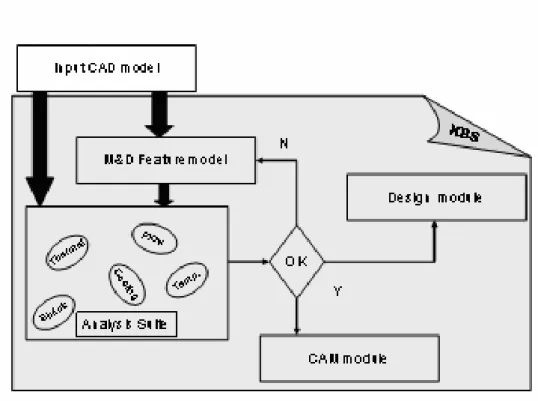
results, and performance simulations, suggestions from the advisory system as well as user preferences, changes are made to the M&D model created by the Pre-Mold processor module. M&D model is a feature based model derived from the input CAD model. All the objects in the feature model are mold, die and tooling features such as plate, vent hole, riser, runner etc. Depending on the selected feature, an intelligent design wizard will pop up to assist the user. The knowledge engine dynamically populates some of the fields and data in this wizard. Here modifications can be made to the feature such as changing the riser height, gate location, parting details, etc. Any changes in the M&D model are now updated by the M&D-making module, which will update the design of components using the Design-system sub-module. The Manufacturing-system sub-module will automatically produce all the relevant process plans, tooling information, CNC code and assembly sequence required to realize the total mold and die. The whole process is iterated till acceptable performance results are achieved as shown in Figure 4. Perceived functionality and interface of each module is shown in Table I.
Figure 4: Iterative Process of Design and Manufacture of Mold & Die
4.1 Knowledge-based Engine
A knowledge engine complements the integrated environment described above. The mould making is accelerated with the aid of such a knowledge-engineered design assistant. Though premature to provide many details, input to such a system includes the following [CYXC2003].
Customer Requirements: providing details on geometry, dimension, materials, etc of the product; design database: providing a library of previously designed molds, sub-assemblies, components, etc; empirical knowledge: providing guidance on material selection, shrinkage, cavity layout, etc; and simulation results giving details on the performance of a given design.
Module Functionality Interface
Pre Mold Processor
Conversion of input CAD data into an M&D Feature model, mesh model suitable for analysis and light models suitable for visualization.
Pre Mold Analysis
Conduct analysis such as flow, temperature, shrinkage, cooling etc and provide simulation of the results.
Mold Design of Experiments
Study various configuration and interact with the Knowledge based engine to derive the process parameters and design parameters for the M&D making module.
M&D Design System Module
Construct and generate CAD models for cavity and mold components such as gates, runners, plates, pins etc by interacting with the Knowledge base.
M&D Manufacturing System Module
Generate process plans, tooling information, CNC code and
assembly instruction for all the M&D components to be manufactured.
M&D Process system module
Control and suggest the process parameters such as flow rate and other properties related to the process.
Table 1: Modules under development for Integrated Design and Manufacture of M&D
It will have interactive features for user interaction, integrate algorithms, heuristic knowledge and other empirical relations. It will also have advisory features on potential components for usage – note that a mold has many parts that are similar in structure and shape that can be
re-used, which are independent of the actual plastic product. Other characteristics of the system will include: methodologies for core & cavity design (product dependent), considerations for assembly and assembling features, mechanism for design improvements, invoking a CAD system that stores designs, linking to pricing/quotation systems, as well as communicating with application that will generate NC codes (when design is finalized).
Figure 5 shows the detailed interactions of the knowledge engine with each module and sub-module defined in the Integrated Design and Manufacture of Mold & Die environment (IDMMD).
Figure 5: Interactions of Knowledge Engine with IDMMD environment
In the diagram above, the shaded boxes (excluding those in the dotted box) represent decision modules on various aspects of design, and underneath each such decision box resides a knowledge-execution box (dotted box) with that intent. For example, in product moldability evaluation, issues such as material thermal expansion, draft angle, the actual process modeling, etc. are taken into consideration. The number of cavities is decided depending on the number of parts that need to be manufactured within a given time. Machine characteristics such as plasticizing capacity, rejection rate, etc also affect the number of cavities [YCD2002]. The runner size depends on the material being molded. Location of runners mostly depends on the topology of runners being used. A branched runner system that avoids runner balancing is the most widely used one. Diameter of the spruce is decided based on the size of the mold, number of cavities, and the amount of plastic that is to be flown within a given time. The gate, which lets the plastic enter the cavity allowing it to fill uniformly, can be located at any point on the perimeter of a circular cavity, but has to enter at the midsection for filling rectangular cavities. Cooling channels (water lines) are located at standard distances from each other and from any wall in the mold. Mold bases may be reused in conjunction with existing cavity and core inserts. A trade off analysis quickly foretells whether it is worth reusing existing inserts or order brand new ones.
4.2 Application Tools
Several application tools for improving the efficiency of mold making are listed below. Some of these exist already; some need to be developed. Discussing the development of such tools, though, is beyond the scope of this paper.
1. Separation planes 4. Injection points 7. Multi-molding 2. Draft angles 5. Ejection points 8. Micro-molding 3. Blending 6. Cooling channels 9. Analysis
Using CAD systems is not simply a matter of creating a product shape. Behind CAD systems there is certain logic about the operations, which is not always evident to the users. CAD systems offer a variety of tools for shape changing, but the systems themselves are so complicated that they are usually implemented by computer scientists who often have little knowledge of manufacturing. It is important to improve modelling algorithms to make them work in a proper technological manner. Also, having manufacturing tools available for designers means that there is a risk that the designer makes manufacturing decisions as part of the shape creation process.
5 Conclusions
The main conclusion is not new: the key to intelligent mold making is knowledge. This paper has identified several existing components and several areas for research. While it is possible to make local improvements the main gains will only come if there is improvement in the knowledge environment across the board from design through manufacturing. In the meantime more limited projects can make significant improvements, both in actual practice and understanding in the mold making environment, leading to efficiency, and hence economic gains.
6 References
BGP2002 Boillat, E., Glardon, R., Paraschivescu, DF. "Optimisation thermique de moules d'injection construits par des processus génératifs", "Proceedings du premier Colloque Interaction Modèle Expérience", eds. G.Lallement, C.Lexcellent, D.Perreux et al.", Vol. 12 Journal de Physique IV, pub. EDP Science, 2002 BPCCsSXI2000 G. Bornet dit Vorgea, P. Pu, R. Clavel, A. Csabai, F. Sprumont, P. Xirouchakis, and M.-T.
Ivora “MicroCE: Computer-Aided Support for DFMA Conceptual Design Phase”, CE 2000, 7th ISPE International Conference on Concurrent Engineering, Lyon, France, July 2000
CIM2001 A.Christman, “CIM Data: Mold Design – A critical and rapidly changing technology” MMS Online, 9, Nov, 2001
CYXC2003 Chan WM; Yan L; Xiang W; Cheok BT, A 3-CAD knowledge-based assisted injection mold design system”, International journal of Advanced Manufacturing Technology, 2003, Vol 22, pp: 387-395. CsSX2002 Csabai, A., Stroud, I., Xirouchakis, P. “Container spaces and functional features for top-down 3D
layout design”, Computer-Aided Design, vol. 34, no. 13, pp.1011-1035, November 2002
HuMa2002 Hu W and Masood S, “An Intelligent Cavity Layout Design System for Injection Molds”, Internationl Journal of CAD/CAM, 2002, Vol. 2, No. 1, pp: 69-75.
LSK2003 G.Levy, R.Schindel, Kruth, J.P. “Rapid Manufacturing and Rapid Tooling with Layer Manufacturing (LM Technologies, State of The Art and Future Perspectives", Annals of the CIRP, vol. 52, no. 2, 2003, pp. 589-609
MCH2001 MOK Ck; Chin KS; Ho JKL, “An interactive Knowledge-based CAD system for Mold Design in Injection Molding Processes”, International journal of Advanced Manufacturing Technology, 2001, Vol 17, pp: 27-38.
Ober99 Oberg, J. “Why the Mars Probe went off course”, IEEE Spectrum, December 1999 PaBe83 Pahl, G., Beitz, W. Engineering Design. Springer Verlag; ISBN: 3540199179, 1983
YCD2002 Yammada J; Chambers TL, Dwivedi SN, “Intelligent Mold Design Tool for Plastic Injection Molding”, ASEE Gulf-Southwest Annual Conference, Lafayette march 20-22, 2002.
YFL2000 Ye XG; Fuh JYH; Lee KS, “Automated Assembly Modelling for Plastic Injection Molds”, International journal of Advanced Manufacturing Technology, 2000, Vol 16, pp: 739-747.