HAL Id: hal-02378510
https://hal.archives-ouvertes.fr/hal-02378510
Submitted on 25 Nov 2019HAL is a multi-disciplinary open access archive for the deposit and dissemination of sci-entific research documents, whether they are pub-lished or not. The documents may come from teaching and research institutions in France or abroad, or from public or private research centers.
L’archive ouverte pluridisciplinaire HAL, est destinée au dépôt et à la diffusion de documents scientifiques de niveau recherche, publiés ou non, émanant des établissements d’enseignement et de recherche français ou étrangers, des laboratoires publics ou privés.
Growth of spheroidal graphite: light versus scanning
and transmission electron microscopies
Jacques Bourdie, Jacques Lacaze, Claudie Josse, Lydia Laffont-Dantras
To cite this version:
Jacques Bourdie, Jacques Lacaze, Claudie Josse, Lydia Laffont-Dantras. Growth of spheroidal graphite: light versus scanning and transmission electron microscopies. International Journal of Met-alcasting, Springer Verlag, In press. �hal-02378510�
International Journal of Metalcasting
Growth of spheroidal graphite: light versus scanning and transmission electron
microscopies
--Manuscript
Draft--Manuscript Number: IJMC-D-19-00110R1
Full Title: Growth of spheroidal graphite: light versus scanning and transmission electron microscopies
Article Type: Technical Paper
Funding Information:
Abstract: Much effort has been put in the past for describing the structure of graphite spheroids and for suggesting a growth mechanism from these observations. Many theories have emerged but none of them is yet fully established and accepted 70 years after the patent on manufacturing spheroidal graphite cast irons. In the meantime, observations with optical light microscopy has become more and more challenged by electron microscopy, either in scanning or in transmission mode. However, conclusions drawn from these various types of observations sometimes appear conflicting. This
unsatisfactory situation is here investigated for three special features of spheroidal graphite, namely: i) The crystalline quality of graphite in the spheroids; ii) The curved leaf-like overgrowth at the outer surface of spheroids; iii) The radial structure that is evidenced with optical light microcopy. The present results lead to sustain that the mechanism of graphite growth remains the same during the whole solidification process of spheroidal cast irons.
Corresponding Author: jacques lacaze
Universite Federale Toulouse Midi-Pyrenees Toulouse, FRANCE
Corresponding Author Secondary Information:
Corresponding Author's Institution: Universite Federale Toulouse Midi-Pyrenees Corresponding Author's Secondary
Institution:
First Author: Jacques Bourdie
First Author Secondary Information:
Order of Authors: Jacques Bourdie jacques lacaze Clausie Josse Lydia Laffont Order of Authors Secondary Information:
Author Comments:
Response to Reviewers: Answers to comments have been uploaded as a file marked as "supplementary material"
Growth of spheroidal graphite: light versus scanning and transmission electron microscopies
Jacques Bourdiea, Jacques Lacazeb, Claudie Jossec, Lydia Laffontb
aSaint-Gobain PAM, Pont-à-Mousson, 54, France
bCIRIMAT, ENSIACET, Université de Toulouse, 31, France cUMS Castaing, Université de Toulouse, 31, France
Corresponding author. Tel.: +33-534323415. E-mail address: [email protected]
Keywords: Spheroidal graphite cast iron, Growth, Crystallinity, Optical microscopy, Scanning electron microscopy, Transmission electron microscopy
Abstract
Much effort has been put in the past for describing the structure of graphite spheroids and for suggesting a growth mechanism from these observations. Many theories have emerged but none of them is yet fully established and accepted 70 years after the patent on manufacturing spheroidal graphite cast irons. In the meantime, observations with optical microscopy has become more and more challenged by electron microscopy, either in scanning or in transmission mode. However, conclusions drawn from these various types of observations sometimes appear conflicting. This unsatisfactory situation is here investigated for three special features of spheroidal graphite, namely: i) The crystalline quality of graphite in the spheroids; ii) The curved leaf-like overgrowth at the outer surface of spheroids; iii) The radial structure that is evidenced with optical microcopy. The present results lead to sustain that the mechanism of graphite growth remains the same during the whole solidification process of spheroidal cast irons.
Conflict of Interest: The authors declare that they have no conflict of interest.
Click here to access/download;Manuscript;text only final_R.docx
Click here to view linked References
1 2 3 4 5 6 7 8 9 10 11 12 13 14 15 16 17 18 19 20 21 22 23 24 25 26 27 28 29 30 31 32 33 34 35 36 37 38 39 40 41 42 43 44 45 46 47 48 49 50 51 52 53 54 55 56 57 58 59 60 61
INTRODUCTION
The process of manufacturing cast irons with graphite precipitated as spheroids was patented in 1949 [1]. Within a few years after this patent, much effort was made to describe the structure of the spheroids and to suggest a growth mechanism from these observations. Already in 1961, Loper and Heine could quote as many theories for spheroidal growth as there were investigators and stressed that nearly each published report proposed a new mechanism [2]. Since then, other theories have emerged but none of them is fully established and accepted 70 years after the patent.
In the meantime, classical optical microscopy (OM) observations have been complemented with electron microscopy observations, either in scanning (SEM) or transmission (TEM) mode. A long-established view [3,4] describes spheroids as being composed of sectors in which elementary growth blocks, see Fig. 1-a, are stacked upon each other, with the –c– basal axis of the graphite crystalline structure being roughly parallel to the spheroid's radius. However, going into more detailed observations, some reports showed additional features which sometimes appeared conflicting depending partly on the means used, i.e. OM, SEM or TEM. This unsatisfactory situation drove us to investigate more particularly three of these special features, namely:
The crystalline quality of graphite in the spheroids as characterized by X-rays and TEM. The curved overgrowth at the outer surface of spheroids as observed by SEM on
deep-etched samples.
The radial line structure that is evidenced with OM, either in dark-field mode or under polarized light.
EXPERIMENTAL DETAILS
The results were obtained from samples that have been cast either in sand molds (Y-blocks 18·14.5·180 mm3) or in a laboratory scale facility for centrifugal casting. This study has been using a pig iron containing 3.85 wt.% carbon and 0.0014 wt.% sulfur. 250 kg batches were melted in an induction furnace and the silicon content was adjusted for being 2.0 wt.% after nodularizing treatment and inoculation. After superheating to 1500°C, 30 kg of melt were poured into a ladle for nodularizing with FeSiMg, the amount of which was higher for melts dedicated to sand-mold castings than for those used for centrifugal castings. The final magnesium content in the iron was 0.024-0.025 wt.% for sand-mold castings and 0.010-0.012 wt.% in centrifugal castings. Further details on casting procedure have been reported
1 2 3 4 5 6 7 8 9 10 11 12 13 14 15 16 17 18 19 20 21 22 23 24 25 26 27 28 29 30 31 32 33 34 35 36 37 38 39 40 41 42 43 44 45 46 47 48 49 50 51 52 53 54 55 56 57 58 59 60 61
previously [5,6]. In the present work, three materials are used which were already presented by Bourdie et al. [6]: unalloyed cast iron cast in sand mold (reference R1) and centrifugally cast (reference C1), Al-alloyed cast iron cast in sand-mold (reference R3).
After standard metallographic preparation of the samples, OM observations allowed to select locations for further analysis with SEM and TEM. Thin foils for TEM could be obtained either using precision ion-beam polishing system (PIPS) or focused ion beam (FIB) technique as detailed previously [7]. The TEM results which are presented here were obtained on a thin foil prepared by FIB.
Fig. 1 optical micrograph of a nearly perfect spheroid (a) and of a spheroid showing a
perturbed central part (b). Fig. (a) is from Bourdie [5], material R1, and Fig. (b) from Tartera et al. [16].
CRYSTALLINE QUALITY OF GRAPHITE
Crystalline quality of graphite in cast irons is an issue which has to do with the growth mechanisms defining graphite shape. One usual way of studying it is using X-rays though TEM investigations are more usual nowadays. X-rays have been used, for example, to characterize the changes in pyrolytic graphite during heat treatment at high temperature [8]. These changes may be followed by the sharpening of the X-ray peaks when highly crystalline graphite blocks develop from the original material. Such an improvement of the crystallinity of graphite has similarly been recorded using X-rays in a Fe-C-Si alloy during long-term heat treatment at a temperature as low as 650°C or 700°C [9]. Another possible modification of graphite is the change in the lattice parameter which decreases for two possible reasons: i) better crystallinity, mostly associated to the decrease in the density of point defects [9,10]; ii) expulsion of foreign elements intercalated within the graphite stacking [11]. While the expulsion of foreign elements is well known in the case of carbon deposits [11], very little has been reported about cast irons. However, this process may explain that magnesium accumulation could be recorded at the graphite/matrix interface in cast irons heat-treated in the austenite field, while no magnesium spike was observed in as-cast material [6,12]. Such an accumulation has also been reported for very slowly cooled cast iron by Itofuji et al. [13]. In turn, the observations by Dierickx et al. [12] and Bourdie et al. [6] strongly suggest that magnesium is not only adsorbed at the surface of graphite during spheroidal growth, but also
1 2 3 4 5 6 7 8 9 10 11 12 13 14 15 16 17 18 19 20 21 22 23 24 25 26 27 28 29 30 31 32 33 34 35 36 37 38 39 40 41 42 43 44 45 46 47 48 49 50 51 52 53 54 55 56 57 58 59 60 61
absorbed within graphite while other elements such as aluminum may not be absorbed so easily [6]. Unfortunately, the spatial resolution, typically from 1 to 10 nm, that would be necessary to move forward in this line is beyond the capabilities of X-rays, even with a synchrotron source.
Detailed OM observations complemented by TEM investigations have led to the here accepted view that graphite precipitates in cast irons are made of the stacking of growth blocks elongated in the prismatic -a- direction of graphite and piling up in the basal -c- direction [3,4,14], see Fig. 1-a. However, a number of studies reported a piling up of distinct blocks with a chevron appearance near the spheroid center as seen in Fig. 1-b [15,16]. Tartera et al. suggested that the pulling out of the central part of the nodule, because of a poor polishing procedure, relieved stresses leading to the formation of this central rosette [16]. This view is supported by the fact that an appropriate preparation of the samples should have led to the observation of a graphite nucleus as the iron investigated was an industrial alloy that had certainly been inoculated. Tartera et al. [16] further stressed that the shape seen in the center of Fig. 1-b generated confusion in that some authors suggested spheroids originate from a minute graphite flake [15]. Though Tartera's statements provide an explanation to the features seen in Fig. 1-b, it does not give any hint on the mechanism leading to the piling up of the growth blocks constituting the spheroids.
In the hope of getting more information on the internal structure of graphite, many reports present OM and SEM images of graphite after etching a metallographic section of the material. Etching can be performed by various means, thermal etching at intermediate temperature (600°C) that leads to graphite partially burning [15]; ion etching [3]; and chemical etching (see for example the work by Hughes et al. [17]). We tried all of these techniques [5] and illustrate thermal etching with the micrographs in figure 2 where the surface of graphite appears porous (figure 2-a) and its stacking quite irregular (figure 2-b). As a matter of fact, whatever the etching technique used, it is quite certain that it affects the surface of graphite precipitates exposed to the medium. As a material reference for their study on spheroidal graphite, Hunter and Chadwick observed first a well-developed graphite lamella which after thermal etching showed a strong surface relief [15]. The relief thus created roughly highlighted the orientation of the basal planes, but the authors insisted on the fact that the scale of the relief is not necessarily related to the scale on which growth occurred. More generally, it seems hardly possible to use OM and SEM images of etched samples to draw
1 2 3 4 5 6 7 8 9 10 11 12 13 14 15 16 17 18 19 20 21 22 23 24 25 26 27 28 29 30 31 32 33 34 35 36 37 38 39 40 41 42 43 44 45 46 47 48 49 50 51 52 53 54 55 56 57 58 59 60 61
conclusions regarding graphite structure, apart from indicating a general trend in the orientation of graphite planes.
Fig. 2 - SEM micrographs of a spheroid section after thermal etching. Figure b is a higher enlargement view of the central area of the spheroid in figure a. Sand-cast alloy R1.
The fact that the central part of the spheroids has been often reported to present a disturbed appearance led a number of researchers to postulate that early growth of spheroidal graphite does not proceed in the same way as during later stage away from the nucleus. In a small spheroid from a sample quenched during early solidification, Qing et al. [4] observed disordered and slightly curved graphite layers close to the spheroid center and concluded that early growth of graphite could be circumferential as proposed by Sadocha and Gruzleski [18]. Also, Amini and Abbaschian assumed that spheroidal growth starts with isotropic precipitation of carbon before circumferential growth takes place [19]. In both works [4,19], growth of sectors - denoted pillars by Amini and Abbaschian – was claimed to proceed after circumferential growth. In contradistinction with these works, our own TEM examinations of large graphite spheroids from sand cast parts showed that fully crystallized graphite develops right from the surface of the nucleus with the appearance of numerous sectors and keep the same characteristic features up to the outer boundaries of the spheroids [20, 21,22]. This latter observation thus suggests that there is no change in the growth mechanism of graphite during spheroidal growth.
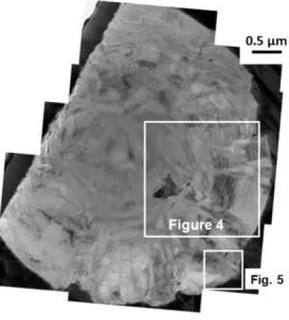
The above contradiction was worthy of further investigation considering rapidly solidified cast irons. On spheroid sections obtained from centrifugally cast samples that solidified in 2-3 seconds and had a mottled structure, we observed by TEM that the graphite appearance in the central part differs from that in the outer part of the spheroids. This is illustrated with Fig. 3 which is a mosaic image of Bright Field TEM micrographs. It is seen that the central part of the spheroid has a smooth appearance while the outer part shows clear contrasts related to the graphite stacking.
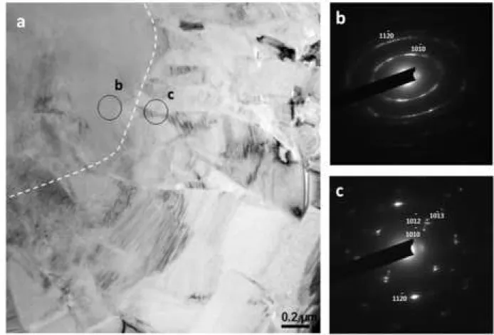
Figure 4-a shows the enlargement of the part of the spheroid labelled “figure 4” in figure 3. The interrupted line separates the central part from the outer part, and the solid circles indicate the locations b and c where Selected Area Electron Diffraction (SAED) patterns were
1 2 3 4 5 6 7 8 9 10 11 12 13 14 15 16 17 18 19 20 21 22 23 24 25 26 27 28 29 30 31 32 33 34 35 36 37 38 39 40 41 42 43 44 45 46 47 48 49 50 51 52 53 54 55 56 57 58 59 60 61
recorded with a 150 nm aperture. In Fig. 4-c, the SAED pattern shows sharp spots indicative of a well-ordered graphite. On the contrary, the SAED pattern at location c is characteristic of a Debye-Scherrer pattern with hk ellipses. This indicates that graphite layers have been rotating around their –c– axis [11]. Moreover, the sharp spots along the ellipses demonstrate that blocks of crystalline graphite are present.
It has been suggested that these misorientations are due to mechanical straining associated with solidification ending in the metastable system which leads to a 4% contraction of the surrounding matrix [7]. In the central part of the nodule, the shear stress may be exceeded leading to rotation of the graphite blocks. Such a situation in rapidly solidified samples impedes any conclusion to be drawn on the mechanism of early growth of graphite, i.e. within the strained and disturbed areas. To sustain this analysis, a more extensive TEM study of the central part should be carried out to characterize the distribution of the blocks by dark field imaging.
Figure 3 – Photo-montage of bright field TEM micrographs of a nearly diametrical section of a graphite nodule of the as-cast centrifugally cast alloy, sample C1. The white squares locate the areas considered for figures 4 and 5.
Fig. 4 –Enlargement of the area indicated as “Figure 4" in figure 3 (a). (b) and (c) are SAED patterns corresponding to the locations labelled b and c in (a).
As mentioned above, sectors are made of the piling up of blocks elongated in the prismatic -a- direction. An estimate of the thickness of these blocks – i.e. in the -c- basal direction – has been proposed by Miao et al. [14], being typically between 50 and 500 nm, while their length may be up to a few micrometers [23]. Hara et al. [24] reported that this thickness increases from the center to the outer part of the spheroids, but their results were apparently based on bright field TEM images which may not be the best suited for such measurements. Qing et al. could illustrate these blocks using dark field imaging in the TEM and noticed that they consist of platelets that were too small to be imaged with the 150 nm in diameter diaphragm they used [4]. Further investigations in this area would be highly welcome as this has to do with
1 2 3 4 5 6 7 8 9 10 11 12 13 14 15 16 17 18 19 20 21 22 23 24 25 26 27 28 29 30 31 32 33 34 35 36 37 38 39 40 41 42 43 44 45 46 47 48 49 50 51 52 53 54 55 56 57 58 59 60 61
the small-scale growth mechanism of graphite in cast iron that is the scale at which graphite shape is determined.
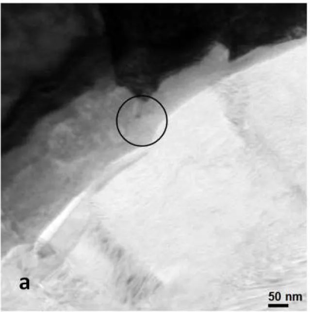
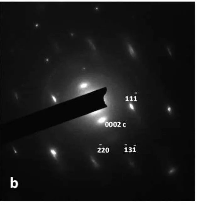
A last feature worthy of mention in this section is the TEM observation by Purdy and Audier of amorphous graphite at the edge of a growth step at the surface of a graphite spheroid [25]. The authors stressed that their results should be treated with a "measure of skepticism", especially concerning information about surfaces. Most of their observations were in fact carried out on crushed samples to generate areas transparent to electrons. It is thus easy to imagine that the graphite particles were heavily altered during this preparation and that the amorphous zone resulted from the rapid rearrangement of carbon atoms at the extreme surface of the residues. During our investigations, we performed TEM observation of the outer surface of several nodules and in a few cases we could observe an outer graphite layer appearing with a different contrast than the bulk graphite, see Fig. 5-a. The SAED pattern recorded on this zone and plotted in Fig. 5-b shows that sharp bcc-iron and graphite patterns are superimposed. Accordingly, the change in contrast appearing between the outer zone and bulk graphite is due to a change in beam absorption while both phases, ferrite and graphite, are crystalline. Qing et al. reported an image similar to Fig. 5-a but of such a high quality that a continuity of the graphite layers may even be seen from bulk graphite to the peripheral zone (their Fig. 11) [4]. To conclude, no amorphous area at the outer surface of graphite spheroids has been found up to now on samples obtained with the modern means for TEM foil preparation.
Fig. 5 - bright field TEM image of the outer surface of a small nodule (a) and SAED pattern recorded in the area defined with the solid circle in a (b). In b, a few spots have been indexed,
the one with four digits relates to graphite, the others with three digits to bcc ferrite. The location of the area shown in (a) is indicated with the lower white square in figure 3.
OVERGROWTH AT THE SURFACE OF SPHEROIDS
Many authors have observed curved overgrowth along the surface of spheroids after deep etching of the materials as illustrated in Fig. 6-a with a sample from the sand-mold casting R1. This so-called cabbage-leaf overgrowth has been suggested as supporting the circumferential growth model proposed by Sadocha and Gruzleski [18] which would reconcile carbon atoms attaching to prismatic -a- planes of graphite while the overall growth
1 2 3 4 5 6 7 8 9 10 11 12 13 14 15 16 17 18 19 20 21 22 23 24 25 26 27 28 29 30 31 32 33 34 35 36 37 38 39 40 41 42 43 44 45 46 47 48 49 50 51 52 53 54 55 56 57 58 59 60 61
direction of spheroids is the basal -c- direction. In a recent work, Qing et al. observed spheroids in samples quenched at various times during solidification and reported that the number of leaves increases with the size of the spheroids [26].
On the same metallographic section on which figure 6-a was recorded, sections through spheroids could be observed. An example is seen in figure 6-b where well-formed sectors are observed which are delineated with the lines radiating from the center of the spheroid section. This observation is clearly incompatible with circumferential growth as already stressed by Gruzleski [27]. The clear relationship of the overgrowths with the underlying sectors in Fig. 6 demonstrates growth proceeds keeping the same morphological characteristics during solidification and later stages of graphite formation.
Recently, we carried out similar observations on samples from centrifugally cast iron, both before and after graphitization heat-treatment [6]. It was found that the surface of the spheroids in the as-cast material was quite smooth with only slightly visible leaves, somehow in agreement with the observations by Qing et al. for small spheroids [26]. After heat-treatment, the leaves appeared as evident as in Fig. 6-a, suggesting they mostly developed by solid-state growth, either during the graphitization treatment for the centrifugally cast material or during cooling for sand-mold cast material.
Fig. 6 - SEM micrographs of a deep etched sample showing outer graphite overgrowths (a) and section of a spheroid in the same sample with clear marks of radial sectors (b). Sand-mold
casting R1.
In the previous section, TEM observations of the central part of small nodules from mottled structures (as-cast centrifugal casting C1) were understood as showing that graphite has been deformed after it precipitated. Accordingly, it was stated that no conclusion could be drawn from these observations as regards the growth mechanism during the early stage of graphite spheroid formation. However, it may be hypothesized that sectors in small spheroids form at the very beginning of their development as seen in large spheroids (Fig. 1-a). The SEM observations above further show that the cabbage-leaf features on the outer surface of spheroids do not imply a circumferential growth of graphite in spheroids. Summing up, it may be stated that there is no change in the graphite growth mechanism during solidification of
1 2 3 4 5 6 7 8 9 10 11 12 13 14 15 16 17 18 19 20 21 22 23 24 25 26 27 28 29 30 31 32 33 34 35 36 37 38 39 40 41 42 43 44 45 46 47 48 49 50 51 52 53 54 55 56 57 58 59 60 61
spheroidal graphite cast irons. Further, it seems that this mechanism is the same for graphite precipitation from the melt and when encapsulated within austenite, either during the eutectic reaction or during solid-state cooling or heat-treatment in the austenite field [6,7]. In this line of thinking, it would be of interest to investigate the possibility of applying to solid-state growth the 2D nucleation and growth model previously developed for spheroidal graphite precipitation from the melt [28].
RADIAL STRUCTURE IN SPHEROIDAL GRAPHITE
Because of the change in orientation of the spheroids’ radii, spheroids appear to be divided in sectors which were seen with TEM to be highly disorientated between each other [21,23,29]. Within these sectors, the graphite growth blocks rotate by low-angle twin boundaries so as to smoothly accommodate the change in orientation [23].
However, a few studies [18,30] reported also on another usual feature of spheroids, namely the radial “line” structure which is clearly evidenced under polarized light optical microscopy, see Fig. 7-a. Sadocha, cited by Gruzleski [27], noticed that these features relate to a relief on the surface of the polished spheroid section and this could be confirmed during the present work by observing samples tilted under the beam of the SEM, see Fig. 8.
Fig. 7 - optical micrograph under polarized light (a) and schematic of the radial line structure, without differentiating sectors (b) and after drawing their boundaries (c). Sand-cast R1
sample.
In Fig. 7-b are drawn the lines seen in Fig. 7-a, with the apparent boundaries of the sectors in red and other lines in black. It appears that the sectors get more and more sub-divided by these lines as graphite growth proceeds from the center to the periphery of the spheroid. This is much in line with the description made a long time ago by Mitsche et al. [3] and also with the increase in the overleaf features reported by Qing et al. [26] as mentioned above. Such a schematic is akin to a process where new sub-sectors are generated and then compete with previous sectors to fill the space, in agreement with the divergent nature of spheroidal growth. This schematic is illustrated in Fig. 7-c.
1 2 3 4 5 6 7 8 9 10 11 12 13 14 15 16 17 18 19 20 21 22 23 24 25 26 27 28 29 30 31 32 33 34 35 36 37 38 39 40 41 42 43 44 45 46 47 48 49 50 51 52 53 54 55 56 57 58 59 60 61
Fig. 8 - SEM micrograph of part of a nodule clearly showing the surface relief. The sample has been tilted with respect to the beam for enhancing the contrast related to the relief.
Sand-cast R1 sample.
Attempts were finally carried out to investigate further the internal structure of graphite spheroids with Electron Back Scattered Diffraction (EBSD) for this versatile technique is most generally easier to handle than TEM. EBSD has rarely been reported for graphite in cast iron because sample surface preparation proves to be highly difficult. Indeed, Holmgren et al. [31] and Yamane et al. [32] reported graphite orientation determined by EBSD for a few isolated locations, but no mapping. During the present work, EBSD was performed on a sample cast in sand-mold with a magnesium-treated cast iron melt to which some aluminum had been added [6]. Because of this addition, graphite appears both as spheroids and with degenerate forms alike compacted graphite. After preliminary trials with various methods, ion polishing was selected for the present work. Fig. 9-a shows the SEM view of the selected area of the sample while Fig. 9-b differentiates the phases according to their indexing, with graphite in red and bcc ferrite in blue. While 100% of the matrix could be indexed, the numerous dark points in the graphite particles show that indexing is much less efficient in this phase with about 50% success. Anyway, Fig. 9-c shows the inverse pole figure along X0-axis for the graphite phase. The color changes in each of the sectors clearly demonstrate that there are subsectors, and the alternate colors along radii may be seen as resulting from growth competition of the various sub-sectors as was suggested with figure 7-c. Such a competition has been previously invoked for describing the numerous sectors found by Transmission Kikuchi Diffraction (TKD) in a small spheroid from a centrifuged casting [34].
Fig. 9 - EBSD analysis of a sample showing both spheroidal and vermicular graphite particles: SEM micrograph of the investigated area (a); mapping of the indexed phases (b);
inverse pole figure for graphite along the X0 axis (c). The scale is the same for all three images. Sand-cast sample R3.
The map in Fig. 8-c shows also the numerous changes in growth orientation in compacted graphite precipitates in agreement with previous reports. Work is ongoing for analyzing in more detail the radial line features by use of Automated Crystal Orientation Mapping (ACOM) in a TEM, which has proved to be quite successful in previous works on spheroidal graphite in cast iron [20,35].
1 2 3 4 5 6 7 8 9 10 11 12 13 14 15 16 17 18 19 20 21 22 23 24 25 26 27 28 29 30 31 32 33 34 35 36 37 38 39 40 41 42 43 44 45 46 47 48 49 50 51 52 53 54 55 56 57 58 59 60 61
CONCLUSION
It is quite interesting to note that natural graphite spheroids of millimeter or centimeter size present the same features as spheroids in cast irons and that describing their growth process is also controversial [36]. The present work has illustrated that using various investigation techniques, namely optical microscopy, scanning electron microscopy and EBSD, and also transmission electron microscopy with associated diffraction, may help to obtain the multi-scale consistency needed for settling these controversies.
Experimental evidence has been gathered to conclude that spheroidal graphite growth proceeds according to a single mechanism during eutectic solidification. This mechanism leads to the formation of sectors in which growth units elongated in the prismatic direction are stacked with their basal direction radially oriented. These sectors develop from the very center of the spheroids, but then multiply and compete between each other. Having clarified how observations at various scales may be reconciled in the case of spheroidal graphite growth, it seems feasible to extend the use of these approaches to the understanding of graphite degeneracy and compacted graphite growth.
References
[1] K.D. Millis, A.P. Gagnebin, N.B. Pilling, USA, Patent, 2,485,760, 1949.
[2] C.R. Loper, R.W. Heine, Graphite formation during solidification of cast iron – Flake, spheroidal, lacy, film and compact graphite, AFS Trans. 69, 583 (1961)
[3] R. Mitsche, G. Haensel, K. Maurer, H. Schäffer, Recherches, par examen au microscope électronique notamment, sur les formes dégénérées du graphite dans les fonts G.S., Fonderie 270, 367 (1968)
[4] J. Qing, V.L. Richards, D.C. Van Aken, Growth stages and hexagonal-rhombohedral structural arrangements in spheroidal graphite observed in ductile iron, Carbon 116, 456 (2017)
[5] Bourdie, Sphéroïdisation du graphite, cas de la fonte centrifugée, PhD thesis, Inst. Nat. Polytech. Toulouse, 2017, https://oatao.univ-toulouse.fr/19739/
[6] J. Bourdie, F. Bruneseaux, P. de Parseval, S. Gouy, L. Laffont, J. Lacaze, Effect of cooling rate and aluminium addition on graphite growth during solidification and
1 2 3 4 5 6 7 8 9 10 11 12 13 14 15 16 17 18 19 20 21 22 23 24 25 26 27 28 29 30 31 32 33 34 35 36 37 38 39 40 41 42 43 44 45 46 47 48 49 50 51 52 53 54 55 56 57 58 59 60 61
graphitization, Proceedings of the SPCI-XI conference, Materials Science Forum, 925, 2018, pp. 20-27.
[7] L. Laffont, R. Jday, J. Lacaze, An electron microscopy study of graphite growth in nodular cast irons, Metall. Mater. Trans. 49A, 1287 (2018)
[8] E. Morinbou, T. Kenji, I. Susumu, K. Kiyoharu, S. Minoru, W.K. Harold, The production and structure of pyrolytic carbon nanotubes (PCNTs), Phys. Chem. Solids 54, 1841 (1993) [9] N. Cowlam, G.E. Bacon, L. Gillott, D.H. Kirkwood, Diffraction measurements of graphite nodules in ferritic steels, Acta Metall. 29, 651 (1981).
[10] K. He, H.R. Daniels, A. Brown, R. Brydson, D.V Edmonds, An electron microscopic study of spheroidal graphite nodules in a medium-carbon steel by annealing, Acta mater. 55, 2919 (2007)
[11] J.N. Rouzaud, A. Oberlin, Structure, microtexture, and optical properties of anthracene and saccharose-based carbons, Carbon, 27, 1989, 517-529
[12] P. Dierickx, C. Verdu, A. Reynaud, R. Fougères, A study of physico-chemical
mechanisms responsible for damage of heat-treated and as-cast ferritic spheroidal graphite cast irons, Scr. Mater. 34, 261 (1996)
[13] H. Itofuji, H. Uchikawa, Formation mechanism of chunky graphite in heavy-section ductile cast irons, AFS Trans. 98, 429 (1990).
[14] B. Miao, K. Fang, W. Bian, G. Liu, On the microstructure of graphite spherulites in cast irons by TEM and HREM, Acta Metal. Mater. 38, 2167 (1990)
[15] M.J. Hunter, G.A. Chadwick, Structure of spheroidal graphite, JISI 210, 117 (1972) [16] J. Tartera, E. Ochoa de Zabalegui, M. Marsal, G. Valera-Castro, Looking at the graphite spheroids as Carl Loper showed us, The Carl Loper Cast Iron Symposium, 2009, Madison, pp. 92 – 103.
[17] G. Hughes, J.M. Thomas, H. Marsh, R. Reed, Origin of etch pits on graphite surfaces, Carbon 1, 339 (1964)
[18] J.P. Sadocha, J.E. Gruzleski, The mechanism of graphite spheroid formation in pure Fe-C-Si alloys, in The Metallurgy of Cast Iron, Proceedings of the second International
Symposium on the Metallurgy of Cast Iron, Georgi Pub., Geneva, Switzerland, 1974, pp. 443 – 456.
[19] S. Amini, R. Abbaschian, Nucleation and growth kinetics of graphene layers from a molten phase, Carbon 51, 110 (2013)
[20] K. Theuwissen, J. Lacaze, M. Véron L. Laffont, Nano-scale orientation mapping of graphite in cast irons, Mat. Charac. 95, 187 (2014)
1 2 3 4 5 6 7 8 9 10 11 12 13 14 15 16 17 18 19 20 21 22 23 24 25 26 27 28 29 30 31 32 33 34 35 36 37 38 39 40 41 42 43 44 45 46 47 48 49 50 51 52 53 54 55 56 57 58 59 60 61
[21] K. Theuwissen, J. Lacaze, L. Laffont, Structure of graphite precipitates in cast iron, Carbon 96, 1120 (2016)
[22] M. Martinez Celis, B. Domengès, E. Hug, J. Lacaze, Analysis of nuclei in a heavy-section nodular iron casting, Proceedings of the SPCI-XI conference, Materials Science Forum, 925, 2018, 173-180.
[23] J.P. Monchoux, C. Verdu, G. Thollet, R. Fougères, A. Reynaud, Morphological change of graphite spheroids during heat treatment of ductile cast irons, Acta Mater. 49, 4355 (2001) [24] T. Hara, T. Maekawa, T. Kawabata, K. Terayama, S. Iken, K. Matsuda, Observation of spheroidal graphite in ductile cast iron by TEM, Arch. Metall. Mater. 58, 431 (2013)
[25] G.R. Purdy, M. Audier, Electron microscopical observations of graphite in cast irons, MRS symposia proceedings 34, 1985, pp. 13 – 23.
[26] J. Qing, V.L. Richards, D.C.V. Aken, Examination of spheroidal growth and austenite solidification in ductile iron, Metall. Mater. Trans. 47A, 6197 (2016)
[27] J.E. Gruzleski, On the growth of spherulitic graphite in nodular cast iron, Carbon 13, 167 (1975)
[28] J. Lacaze, J. Bourdie, M.J. Castro Roman, A 2-D nucleation-growth model of spheroidal graphite, Acta mater. 134, 230 (2017)
[29] J. Lacaze, K. Theuwissen, L. Laffont, M. Véron, Misorientations in spheroidal graphite: some new insights about spheroidal graphite growth in cast irons, IOP Conf. Series: Mater. Sci. Eng. 117, 2016, 012024
[30] H. Morrogh, Graphite formation in grey cast irons and related alloys, BCIRA J. 5, 655 (1955)
[31] D. Holmgren, R. Källbom, I.L. Svensson, Influences of the graphite growth direction on the thermal conductivity of cast iron, Metall. Mater. Trans. 38A, 268 (2007)
[32] K. Yamane, A. Sugiyama, T. Nagira et al., Influence of Mg content on graphite growth in hypereutectic cast iron and crystallographic feature of graphite, J. Japan Foundry Society 86, 461 (2014)
[34] E. Brodu, E. Bouzy, J.P. Fundenberger, B. Beausir, L. Laffont, J. Lacaze,
Crystallography of growth blocks in spheroidal graphite, Proceedings of the SPCI-XI conference, Materials Science Forum, 925, 2018, 54-61.
[35] K. Theuwissen, L. Laffont, M. Véron, J. Lacaze, Crystallography of graphite spheroids in cast iron, Int. J. Met. Cast. Res. 29, 11 (2016)
[36] J.A. Jaszczak, Graphite: flat, fibrous and spherical, in Mesomolecules, G.D. Mendenhall and J.F. Liebman (Eds.), Chapman & Hall, 1995, pp. 161 – 180.
1 2 3 4 5 6 7 8 9 10 11 12 13 14 15 16 17 18 19 20 21 22 23 24 25 26 27 28 29 30 31 32 33 34 35 36 37 38 39 40 41 42 43 44 45 46 47 48 49 50 51 52 53 54 55 56 57 58 59 60 61
We would like to thank the three reviewers for their interest in this work. All comments were appreciated and were considered as detailed below. In fact, this submission is undoubtedly a research document, but details about the origin of the micrographs and, consequently, about the samples were missing in the original submission. We hope that this has been appropriately corrected. The references and figure numbers which are indicated in the answers are those in the original submission, with the new number for figures indicated between parentheses. Changes in the text are highlighted in yellow.
Reviewer #1: Revisions advised: The impact of the paper would be greatly enhanced by using EBSD at higher magnifications, and analyzing the stages of growth by comparing annealed and as-cast samples.
Answer – As shown with figure 8 (9), EBSD is not well suited for studying graphite because the indexation yield is low even after clever preparation of the surface. This is not expected to change at higher magnification. TKD in a SEM [33] showed not to be better while ACOM in a TEM [34] has been used with much more success. This is the technique that is now used to complement the results in this submission. Comparison of the microstructure of centrifugally cast and graphitized samples has already been reported [21].
Revisions required: See attached comments.
Page 4, Line 1: References should be given for better crystallinity and expulsion of foreign elements.
Answer – some referencing has been added.
Page 4, Line 5: Author says very little has been reported about this in cast irons but then contradict by citing several references.
Answer – well, 3 references is more than a couple but yet not a lot and these are all references we know.
Page 6 Line 13: "Arcs are elongated…Such a deformation must be due to mechanical straining." Elongation of the arcs can be due to the orientation of the crystals present, not with the strain. Strain can be read from the SAED as an offset in values corresponding to d-spacing (radius). Also Fig 3 B shows oval elongation which is representative of severe stigmation and accurate determination of the d-spacing are needed particularly considering strain in the crystal.
Answer – Astigmatism has been checked for TEM observations as they were intended to make HRTEM imaging. Possible source of stigmation could be the presence of iron particles in the graphite but this does not appear to be the case for this investigation. However, it is agreed that the arc elongation in figure 3-b is by far too large for being representative of elastic straining and, in fact, we selected in our collection the SAED pattern where it was the largest (In reference [21] in which we suggested straining of the central part of the spheroids, the arc elongation which was shown was much more limited). The remark of the reviewer thus points out a poor wording in the original submission. In agreement with the reviewer’s comment, we agree that the hk ellipses in the
diffraction pattern are characteristic of graphite layers being rotated around the c axis as described
by J.N. Rouzaud and A. Oberlin (Carbon, 27, 1989, 517-529). However, sharp spots are observed along the ellipses which suggest that thick blocks of similarly oriented graphite layers are still present. These observations suggest that the misorientations have appeared when the stresses induced by straining raised above the shear stress of graphite [21]. The text has been modified accordingly to clarify this issue.
Supplementary Material Click here to access/download;Supplementary
Page 6 Line 45: "Platelets that were too small to be imaged with the 150nm diaphragm..." Alternative techniques such as FFT and inverse-FFT to measure the d-spacing of sub-150nm particles.
Answer – The word "platelets" designates here the same as "blocks" which are assumed to be the smallest "building bricks or stacks of graphite layers" in cast irons. They are often reported to be 100
to 500 nm in thickness. Evaluation of d spacing was not the aim here.
Page 6 Line 60: "Most of their observations were carried out on crushed samples.." The author uses a case from previous work where the sections were made using crushed samples. However, they do not mention what technique they used.
Answer – Following this remark and the query from reviewers #2 and #3 we have made clearer that all images but figure 1-b are our own work and added details on the samples and their preparation. TEM samples were prepared with FIB technique.
Page 7 Line 4: "In a recent study, we performed TEM…" How was this sample prepared?
Answer – This is now indicated.
Page 7 Line 18: "These observations agree with the fact that amorphous graphite can be generated only with growth rates..."
Saying that this structure can "only" be formed this way is risky because it states an observation as an absolute and has a low probability of being true.
Answer – This sentence has been removed.
Page 7 Line 56: "This incompatibility was already stressed by Gruzleski who denied the presence of sectors." This theory was "stressed" in 1975 and with limited information, not including TEM. Stating that earlier thoughts on the topic were incompatibilities is not as accurate as describing it as developing knowledge.
Answer – Translated in French, the sentence does not appear as a statement against the work by Gruzelski. However, to cope with this comment, the two sentences lines 55-57 have been merged to give: "Instead, well-formed sectors are observed which are clearly incompatible with circumferential growth as already stressed by Gruzleski.
Page 8 Line 18: -Why not do CT on these structures to look at the interior without destroying the sample or cutting it causing distortion? See for example, "Synchrotron quantification of graphite nodule evolution during the solidification of cast iron"
Answer –In their work, Azeem et al. used a synchrotron radiation and recording conditions giving a resolution of a few microns, i.e. at least one order of magnitude too coarse for the details to be investigated. Further, I am not sure that there is a synchrotron source available at present that would be able to perform imaging and diffraction at the same time with the needed time and space resolutions. An example of the present limits of CT can be found in the report by Moniri et al. (scientific reports, 2019; 9:3381) on the effect of trace impurities on Al-Si eutectic modification. Let us say that your proposal opens exciting suggestions for the future.
Was the sample prepared with FIB? What are the temperatures experienced with focused ion beam. Carbon can crystallize at low temperatures. Is it possible that the crystal structure simply change by this technique?
Answer – Carbon starts crystallizing to graphite at temperatures higher than about 500°C (Rouzaud, Oberlin, Carbon, 27, 1989, 517), a temperature which is hopefully not reached during FIB preparation. Moreover, the same TEM observations could be made on samples prepared by FIB and by the more classical PIPS procedure which suggests that FIB did not change the graphite structure, at least not more than FIB. What we have experienced is that graphite gets amorphous after extensive TEM examination of a given area. This radiation damage is described as ‘Knock-out’ and is
generated by electrons for sample temperature lower than 300-400°C; and it disappears for temperature above this range (F. Banhart, Rep. Prog. Phys. 62, 1999, 1181). In our previous publications, we mentioned that care was taken for minimizing the time during which the beam was focused on the observed areas, and this precaution was applied as well during the present investigation.
Page 8 Line 51: They twist to smoothly accommodate the change in orientation? Is the author refereeing to twinning between sectors?
Answer – Yes we do, this was an error which has been corrected. « Twist » has been replaced by
"rotate by low-angle twin boundaries".
Page 9 Line 17: If the sectors "compete to fill space," What is the largest theoretical size a sector can grow? Is it possible for the sector to ever encompass 360˚ around the spheroid, or is there some equilibrium angle that has a greater probability of forming?
Answer – A couple of publications have dealt with this interesting aspect of spheroidal growth. Based on energetic arguments, a Japanese author has calculated that the number of sectors in a spheroid should be of the order of 400. However, this evaluation depends on the size of the spheroid. Worth of mention is the fact that "squared" nodules, with 4 well-defined sectors in the metallographic section of observation, have been reported. Thus, again an exciting fully open question!
Page 9 Line 38: Why were both aluminum and magnesium added. One is incorporated into the graphite spheroids and one is expelled into matrix. Why not one or the other to minimize possible causes of the results?
Answer – It may be interesting to add some aluminium to cast iron for triggering nucleation of graphite (through the formation of Al oxides and nitrides), but it may also that aluminium has to be considered because it is present as a result of the use of scraps for melt preparation. In this latter case, aluminium is known to counter the spheroidizing treatment and this was in fact the aim of the experiments of evaluating its effect [7, 9]. We were quite happy to notice it does not behave exactly as magnesium. This difference may be meaningful for understanding the effect of low level elements on graphite shape, and is an up-to-date issue (see for example the paper just accepted in Materialia: https://www.sciencedirect.com/science/article/pii/S2589152919302674).
Reviewer #2: General Comments:
The main conclusion of the paper is that “the mechanism of graphite growth remains the same during the whole solidification process of spheroidal cast irons”. This statement runs contrary to the current knowledge on the subject, which supports several mechanisms active in the two or three stages of the development of the spheroidal (SG) graphite morphology. It is an oversimplification of the problem.
Answer – That there are stages in the growth of spheroidal graphite is fully agreed: free growth in the liquid, growth in an austenite envelop during solidification and then during cooling, and finally growth when a ferritic matrix forms during the eutectoid transformation. Noteworthy, a wealth of works has reported results showing no difference in the graphite formed during the two stages associated to solidification. Further, our results on graphitization of mottled cast irons show that the graphite in the nodules appears similar after graphitization than in as-cast state. So, even though there may be different stages, considering growth of graphite proceeds along one single mechanism during solidification and high temperature graphitizing heat-treatment does not go against the current knowledge but possibly against a selected part of available literature.
It is not clear whether this is a review paper or a research paper. As a review paper it suffers of over-quotation of the authors own work (8 out of 35), compounded by the omission of several recent pertinent publications in reputed journals such as Acta Materialia, Scripta Materialia, Metallurgical and Materials Trans., and Int. J. of Metalcasting. As a research paper it lacks the required information on chemical composition of the samples and their preparation, as well as details on the interpretation of many figures. It has some inaccuracies and inconsistencies that tend to bias the interpretations. While it is acceptable as a conference paper, it will require major mandatory revisions to be accepted for publication.
Answer – The paper was definitely intended to be a research paper, not a review. It is agreed that it lacked experimental information in the original submission, this has been corrected.
Revisions advised:
The impact of the paper would be greatly enhanced by using EBSD at higher magnifications, and analyzing the stages of growth by comparing annealed and as-cast samples.
Answer – As shown with figure 8, EBSD is not well suited for studying graphite because the Answer – As shown with figure 8 (9), EBSD is not well suited for studying graphite because the indexation yield is low even after clever preparation of the surface. This is not expected to change at higher magnification. TKD in a SEM [33] showed not to be better while ACOM in a TEM [34] has been used with much more success. This is the technique that is presently used to complement the results in this submission. Comparison of the microstructure of centrifugally cast and graphitized samples has already been reported [21].
Revisions required: See attached comments.
p3, line 58 to p4, line 18: the discussion on pyrolytic graphite, improvement of crystallinity of graphite through heat treatment, and magnesium accumulation at the interface or in the graphite is completely ignored in the rest of the paper, and it is not used to support any theory by the authors. It is thus unnecessary and should be removed.
Answer – The title of the section is "crystalline quality of graphite" and it was thought interesting to refer to results dealing with aspects that can affect it. Some changes have been made to the text to clarify the relation of this paragraph with the remaining of the section
p5, line 27: the authors state "In contradiction to these previous works, TEM examination of large graphite spheroids from sand cast parts showed that fully crystallized graphite develops right from the surface of the nucleus with the appearance of numerous sectors [17-19]. These latter observations thus suggest that there is no change in the growth mechanism of graphite during spheroidal growth." This is an unsupported jump to conclusions; the fact that TEM work on a large SG does not exhibit circumferential growth does not eliminate the possibility of the occurrence of such growth in other nodules. Actually, the consensus is that circumferential growth is the preferred mechanism during the growth of graphite directly from the liquid, and is readily observable in small nodules (see Lalich work).
Answer – We are not sure to which work by Lalich the reviewer is making reference to so that we cannot comment on it. What happens is that the statement by the reviewer can be just reversed: there is enough information in the literature for stating that the circumferential growth mechanism has been found not appropriate in many spheroids, and in none of those we have investigated so far. Finally, the wording "consensus" that was used in the original submission has been withdrawn as it looks too much alike "compromise" in French.
Fig. 2: is this an original figure? If not, what is the source?
Answer – Apart the micrograph of figure 1-b, all are from our works. This is now clearly indicated.
p6, line 7: authors' statement "Hara et al. [20]. This latter work and the present results show that graphite in the nodule center is disoriented, though definitely not amorphous" takes liberty with, and
contradicts Hara et al. own statement, which is: "The spheroidal graphite had a three-fold internal structure, with an amorphous-like central region, annual rings of a layered intermediate region, and an outer region made up of large polygonal crystalline platelets in a mosaic-like structure." Hara's statement is not only in direct contradiction with the authors of the submitted manuscript regarding the crystallinity of graphite in the central region, but also unequivocally supports the mechanism of circumferential growth ("annual rings of a layered intermediate region").
Answer – Quoting properly our statement would have given: "On the contrary, the SAED pattern at location b shows “arc-like 0002 diffracted spots (not ring)” to use the same wording as Hara et al. [20]. This latter work and the present results show that graphite in the nodule center is disoriented, though definitely not amorphous." The second sentence was not intended to associate Hara et al. to our conclusions but we agree that the formulation may have been ambiguous. We thus reformulated the whole paragraph and withdrew any reference to Hara’s work from it.
Concerning circumferential growth, the statement from Hara et al. work quoted by the reviewer appears in the conclusion of their paper but strictly relates to their figure 3. If the present submission had been a review, we would have stressed that the micrograph in this figure 3 does not fit with this conclusion: area 2 and 3 in this figure (reproduced below) do not show circumferential growth but instead neighboring sectors which are slightly misoriented between each other and in which graphite blocks are straight. This inconsistency may be related to the ambiguous meaning carried out by the word "circumferential". Summing up, our observations are exactly the same as those of Hara et al. though we cannot see circumferential growth where there is not.
Part of figure 3 from the work by Hara et al.
p6, line 18: the authors state "The observed straining in rapidly solidified samples impedes any conclusion to be drawn on the mechanism of early growth of graphite, i.e. in the strained and disoriented areas." The "observed straining" is a hypothesis unsupported by Hara's work.
Answer – This sentence did not make any reference to the work by Hara but to our previous work [21].
p7, line1: Referring to the work of Purdy and Audier showing amorphous graphite at the edge of a growth step at the surface of a graphite spheroid, the authors state: "It is thus easy to imagine that the outer layers of graphite were broken during this preparation and that the amorphous zone
resulted from the rapid rearrangement of carbon atoms." That is a curious hypothesis: rapid atom carbon rearrangement at room temperature?! Rearrangement from what state?
Answer – Curious question: if an anisotropic material such as graphite is broken perpendicularly to its strongest atomic bonds, what are the most outer atoms doing at the broken surface. They certainly do not hang in vacuum. The end of the paragraph has been modified so as to reach a consensus.
p8, line 2: "After heat-treatment, the leaves appeared as evident as in Fig. 5-a". The caption of the figure should state that this is a heat-treated sample. But then why this figure at all, since the authors are trying to demonstrate that "the mechanism of graphite growth remains the same during the whole solidification process of spheroidal cast irons" as stated in the abstract?
Answer – Information about the samples have been added. There is nothing here about the growth mechanism, please see below.
Fig. 5-b: The SEM micrograph represents a section through a spheroid that the authors use to state "Fig. 5-a does not show any feature that could be related to the circumferential growth mechanism as demonstrated in Fig. 5-b." Previously the authors stated "it seems hardly possible to use LOM and SEM images of etched samples to draw conclusions regarding graphite structure". Yet now they use the figure to support their theory affirming that: "The SEM observations above further show that the cabbage-leaf features on the outer surface of spheroids do not imply a circumferential growth of graphite in spheroids." This is an inconsistency which requires removal of Fig. 5.
Answer – What shows figure 5-b is that the so-called cabbage-leaves as those seen in figure 5-a are in fact delineating the outer surface of the sectors. Thus, these morphological characteristics (and not the structure) demonstrate that the leaves are not wrapping around the spheroids. Hence, the two micrographs in figure 5 are complementary and highly demonstrative. Some changes have been made to the text to strengthen this complementarity.
Fig. 6-b,c: the boundaries in 6-c ignore a large number of those in 6-b; one cannot have it both ways: draw boundaries as seen on the LOM, and then ignore some of them to fit the size needed for their theory. The figure should be removed.
Answer – Right, not all of the boundaries were drawn and this at least for one physical reason: any relief is going to give two lines under polarized light which are more or less parallel on most of their length. Other discrepancies are possible, the aim was not to make a quantitative analysis but to convey an observation and the way it was understood. Once realized, growth competition between sectors is just obvious owing to the divergent nature of spheroidal growth.
Fig. 8: Why is this figure and the discussion on EBSD included in the paper? It is not used to support the hypothesis advanced by the authors. Could the authors demonstrate its usefulness in the current context?
Answer – At the bottom of page 9, i.e. at the end of the presentation of this figure 8 (9), it is stated that the EBSD maps confirm the growth competition that is described in figure 6 (7). This could have supported the use of EBSD if the technique was easier to use than it is.
References: the list of reference is woefully incomplete.
Answer – It depends on the objectives, this is now clearly a research paper.
Revisions required:
The paper should be rewritten either as a review paper or as an original research paper. In the first case, it should include discussion of existing reports, even when they disagree with the authors opinions, and the conclusions should be left to the readers. In the latter case, the paper should be structured accordingly to include section on experimental method, characterization, etc. The comments to author should be addressed and resolved.
Answer – This is now an original research paper with some experimental details and reference made to previous works where all details have been given. We do hope all comments have been resolved.
Reviewer #3: General Comments:
This paper does include good summaries of previous works by others. Some of the works cited are very good studies done by well-known researchers. It should be able to draw good attention from the readers even though I don't agree with many findings in the paper. Expressing new or different opinion is challenging but should be encouraged. This paper may lead to further discussions by other researchers which held different opinions.
Answer – thanks for your encouragement.
This paper doesn't follow standard writing format including experimental procedure, results and discussions separately. Sometime it's hard to tell if the author was discussing their own results or interpreting other people's data.
Answer – The text has been modified to hopefully raise all doubts.
The experimental data listed in the paper was not really complete or maybe I wasn't able to follow the authors' discussion well enough. It was mentioned % of graphite crystallization, but where was the data collected about % of crystallization? The discussions were not sufficient regarding of their own data. For example, Figure 3 and 4 should convey a lot of information but the discussion were only a few sentences. I would expect more discussions.
Answer – see below
I recommend to accept this manuscript and recommend minor revisions.
1. The author should label in the figure to point out the exact feature being discussed. This should be improved to allow readers to follow the discussion more easily.
Answer – This has been done to some extent.
2. Some of the recent works by others were recognized and discussed. It may be interesting to include new findings from Dr. Stefanescu's recent publications.
Answer – This does not appear appropriate for an original research paper, i.e. a paper which is not intended to discuss literature but to reference works which are directly relevant to those particular aspects which are dealt with, in particular TEM results.
3. This paper doesn't adopt typical format including experimental procedure, results and discussions separately. The experimental results are mixed with discussions or comparisons with literature results. Sometime it's hard to follow the discussions or comparisons.
Answer – As for experimental details, this is because the work shown here is related to studies made over the last years which have been published with full details. However, an experimental section has been added and an effort has been made to clarify what is our own work and what is from literature.
4. I did not really get a clear understanding about how the % of crystalline graphite related to growth of SG? What kind of data were collected regarding of this discussion? Could the author provide specific data, like % of crystallization if possible?
Answer – In the community dealing with graphite in cast iron, the only data which are reported are the values and sometimes distribution of c spacings which is closely related to the density of point defects (see Qing et al., 2017, [14]).
5. When talking about prismatic direction, it should be a direction instead of a direction. Same for -c- direction. This should be checked throughout the paper.
Answer – this has been corrected, adding also "basal" or "prismatic" when appropriate
6. In line 2 of page 7, I recommend to change the word broken by modified/altered. The outer layer graphite structure may be altered easily since basal planes slip easily.
Answer – thank you for the suggestion, the sentence has been changed to "It is thus easy to imagine that the graphite particles were heavily altered during this preparation and that the amorphous zone resulted from the rapid rearrangement of carbon atoms at the extreme surface of the residues.” Also, the following sentence has been added at the end of the paragraph: “With modern means for TEM foil preparation, no amorphous graphite at the outer surface of the spheroids has been reported".
7. In ilne 20 of page 7, I am not sure how could conclude that "These observations agree with the fact that amorphous graphite can be generated only with growth rates as encountered in vapor deposition which are order of magnitude higher than those prevalent in casting". Was any work mentioned here used vapor deposition?
Answer – Agreed, the sentence has been removed.
8. In page 7, the author mentioned that Fig. 5b didn't show center feature. That didn't imply there wasn't different growth pattern in the center. It might be simply because the low magnification could not resolve the center feature of submicron size.
Answer – Figure 7 (8) shows an enlarged view of the central area of a spheroid in the same sample. What is seen at the intersection of the radial lines is due to the fact that the section was not perfectly diametrical. If it had been, the lines would have been seen starting from the nucleus, which is generally 1-2 µm in diameter, i.e. larger than the gap seen in Fig. 5-b (6-b) or 7 (8).
9. The discussions about Figure 3 and 4 may not be sufficient. I would like to see more details here. Where was the SADP collected in terms of distance from SG center? Since this tells the growth stages. A low mag image may be helpful to show the locations for SADP.
Answer – A photomontage of BF TEM images has now been added that encompasses the whole spheroid section. Please note that the sample was taken from an as-cast centrifugally cast alloy, so that only growth from the liquid could be involved in the formation of the spheroid.
10. It was not clear to me if the author supports that there are different growth stages following different mechanisms or not. Their SADP showed differences but the author said no difference somewhere else. I was confused.
Answer – There are certainly different stages of growth (directly from the liquid and then by diffusion of carbon through the austenite shell) but this does not imply the atomic mechanism of growth changes. Part of this contribution was dedicated to demonstrate this and to propose explanation to the peculiar SADP recorded at the center of spheroids in rapidly solidified (“quenched”) cast iron.