Publisher’s version / Version de l'éditeur:
Conference Proceedings (Volumes 1 And 2) of the International Heavy Haul
Association’s Sts-Conference on Wheel / Rail Interface, 1999
READ THESE TERMS AND CONDITIONS CAREFULLY BEFORE USING THIS WEBSITE. https://nrc-publications.canada.ca/eng/copyright
Vous avez des questions? Nous pouvons vous aider. Pour communiquer directement avec un auteur, consultez la
première page de la revue dans laquelle son article a été publié afin de trouver ses coordonnées. Si vous n’arrivez pas à les repérer, communiquez avec nous à [email protected].
Questions? Contact the NRC Publications Archive team at
[email protected]. If you wish to email the authors directly, please see the first page of the publication for their contact information.
Archives des publications du CNRC
This publication could be one of several versions: author’s original, accepted manuscript or the publisher’s version. / La version de cette publication peut être l’une des suivantes : la version prépublication de l’auteur, la version acceptée du manuscrit ou la version de l’éditeur.
Access and use of this website and the material on it are subject to the Terms and Conditions set forth at
Perspectives on metallurgy and contact mechanisms
Kalousek, Joseph; Magel, Eric; Grassie, Stuart
https://publications-cnrc.canada.ca/fra/droits
L’accès à ce site Web et l’utilisation de son contenu sont assujettis aux conditions présentées dans le site LISEZ CES CONDITIONS ATTENTIVEMENT AVANT D’UTILISER CE SITE WEB.
NRC Publications Record / Notice d'Archives des publications de CNRC:
https://nrc-publications.canada.ca/eng/view/object/?id=e6bc32a8-8e11-45f2-a019-33d0e24a71b7
https://publications-cnrc.canada.ca/fra/voir/objet/?id=e6bc32a8-8e11-45f2-a019-33d0e24a71b7
Perspectives on Metallurgy and Contact Mechanisms
Joseph Kalousek and Eric Magel, National Research Council Canada Stuart Grassie, Consulting Engineer, Glasgow, UK
Summary:
The major reasons for deterioration and premature replacement of rail on heavy haul track are reviewed with particular regard to the mechanical and metallurgical factors influencing various damage mechanisms. Damage to the rail is principally a result of wear; rolling contact fatigue; other types of fatigue defects; corrugation; plastic flow and head crushing; martensitic layers, particularly from wheelburns; and batter of joints and welds. Some consideration is also given to wheel damage processes. Conclusions are drawn regarding means of reducing rail (and wheel) damage on existing systems. Future developments, primarily in the field of metallurgy, are also discussed. The proposed treatments address both mechanical and metallurgical factors to contain the damage. Considerable substantiation is provided for the proposals from an extensive review of published work.
1 INTRODUCTION
Railway engineering in the 20th century can be characterized by one word: change! Although there has been little modification to the basic design of rails and freight wheels, their shape, mechanical properties and internal qualities have been progressively improved by utilizing technological advances in steel refining and rolling or casting processes. 1880 rail examined by Kobayashi et al [1] exhibited low but uniform hardness throughout its cross-section; a sulfur print demonstrated severe segregation in the center of the web and the fracture toughness of the steel was compromised by high sulfur inclusions. Despite this our predecessors must be saluted, as they struggled with the same issues we struggle with today. Without their efforts we would not have progressed as far as we have.
Over the last three decades, the rate of change has accelerated considerably. The average freight car axle load has doubled and annual tonnage on main line track has quadrupled. In spite of this, the typical rail wear-life doubled in tangent track and tripled in curves [2, table 1]. A main initiator of these increases in rail wear life was the improvement in metallurgical and mechanical properties of rail steel [3]. Upgraded truck design and maintenance, lubrication and profile grinding have also contributed to the wear life increase of the rail.
It is expected that the historic trend of increasing axle loads will continue unabated. At the same time, heavy haul railroads strive to increase the wear life of rail and wheel or at least maintain these at the current levels. Although we can not know in detail how these challenges will be met over the next twenty years, we can assume that further improvements in rail metallurgy, bogie performance, rail grinding strategies and friction management will make significant contributions.
This paper reviews past achievements in rail steel making practices, identifies the required properties of current and future rails from the perspective of contact mechanics and briefly explores the impact of friction management, bogie characteristics and grinding on future rail performance. 2 RAIL DAMAGE
Regardless of variations in tonnage, speeds and environment, all heavy haul railroads face a number of opponents in the battle to increase rail life including wear, surface contact fatigue, contact fatigue defects, plastic flow, corrugations, weld batter, and martensite formation. 2.1 Wear
The top of the rail is subject to high contact stress and relatively low levels of slip, which typically generates magnetite (Fe4O3) through an oxidative, wear process [4].
The resulting particles are micron to sub-micron in size and mix with various environmental contaminants that compose a protective layer on the top of the rail. The composition of this layer and frequency at which it is flushed from the rail dictate the oxidative wear rate. Abrasive wear, caused by silicate rich contaminants or sand from locomotives, can double or triple the oxidative wear rates. Wheel/rail abrasion is common near road crossings, on upgrade sections of track, in sidings and in rail yards.
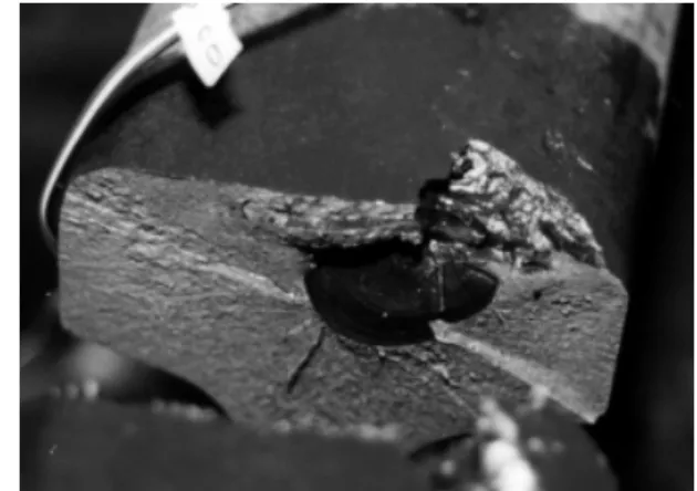
In dry curves, the gauge face/wheel flange contact is subject to high flange force (often 30- 60% of the wheel load), and a high level of slip. Gauge face wear is dominated by adhesion; cold welding and subsequent tearing of metal [5,6] that generates shiny metallic wear particles (Figure 1). In addition to flange load and slip [7], the wear rate is strongly influenced by lubrication [8], microstructure and hardness [9,10,11,12], and grinding practices [13].
Figure 1: Shiny wear particles (“dandruff”) from adhesive wear at the wheel flange contact with the outside rail in a sharp curve.
2.2 Rolling Contact Fatigue (RCF)
A typical piece of heavy haul rail carries about 3 million wheel load cycles every 100 MGT; freight wheels with a life of 240,000 kilometers undergoe about 80 million rotations. A percentage of these cycles, under conditions of high friction and high contact stress deform the wheel and rail metal in the direction of the applied stress [14]. The accumulating increments of deformation “ratchet” [15,16] the surface layer until it reaches its ductility limit, then fractures and generates a surface crack [17,18] (Figure 2). The rate of surface deterioration depends primarily on the friction coefficient, maximum contact stress and strength of the steel [16,19,20,21] (Figure 3).
Figure 2: Ratcheting in rail steels associated with contact fatigue
Figure 3: Shakedown diagram for line contacts
The rate and depth of crack propagation is strongly influenced by the presence of greases or water at the crack face [22]. Dry cracks typically propagate less than a couple of millimeters into the surface to a depth governed by the limiting value of the surface shear stress. Lubrication of the crack faces by water, grease or other contaminants allows a crack to propagate deeper by Mode II (shear) propagation (Figure 4a). Additionally, water entrapped in inclined surface cracks can be hydraulically pressurized by the passing contact load, propagating surface cracks rapidly by Mode I tensile stress (Figure 4b).
a b
Figure 4: a) Reducing the crack-face friction accelerates Mode II crack propagation. b) hydraulic compression by entrapped water
leads to very rapid crack propagation in Mode I. [23]
Based on the combination of the above influencing factors, the RCF damage can range from microscopic cracks to head checks to broken rail [13]. Head checks [24] are RCF cracks that grow initially at an acute angle to the rail surface. If the inclined cracks coalesce or turn towards the rail surface, a shell develops.
Deep seated shells usually develop at the gauge corner of the high rail (Figure 5), and are commonly the result of gauge corner collapse due to excessive loading of the rail corner [25,26]. Clean steels in combination with grinding to a transverse profile with moderate gauge corner relief is an effective strategy for minimizing the occurrence of these types of shells.
Figure 5: Transverse defect and broken rail from head checking.
2.3 Defects
Rail defects significantly reduce rail life [27,28]. Among the numerous types of rail defects are the detail fracture, broken rail (pull apart), broken weld, vertical and horizontal split head and transverse defect from a deep seated shell.
All are difficult to eradicate in heavy haul track. Early detection is the best method to deal with detail fractures [28], while rail destressing and better welding practices can address problems with broken rail and welds respectively. Horizontal split heads are typically associated with worn, head hardened rails. Deep head hardening helps to alleviate these types of defects, even on rail with expanded wear limits. Although some suggestions as to the cause of vertical, split heads have been made [29,30] more research is needed before effective means are found to alleviate this defect. It is universally accepted that transverse defects from shells initiate at alumina-silicate oxide inclusions [31,32]. In some instances, head checks progress into transverse defects (Figure 6), which lead rapidly to a broken rail and, if not detected and removed, serve as a derailment hazard. The transverse defects from deep-seated shells are especially difficult to detect at their early stages of growth, because they are shielded by the initiating shell crack.
a b c
Figure 6: Examples of shell fractography: a) open shell with crack growth rings visible but with no head checks. b) open shell with head
checks (above the coin) present simultaneously. c) closed shell with transverse crack could result in a broken rail.
2.4 Corrugations
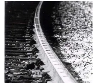
Corrugation refers to periodic irregularity of the rail (and sometimes wheel) surface which is often difficult to measure but is visible to the naked eye. Corrugation gives rise to high dynamic forces between the wheel and rail, and degrades ballast and other track components at often overlooked but substantial costs [33,34]. It may also be a source of noise and associated litigation.
In heavy haul systems, corrugation is most common where heavy unit trains run at a consistent speed [35]. Corrugation initiates at discrete railhead irregularities, including welds and joints. The excitation of a vertical resonance, in this case the unsprung mass of the heavily loaded cars on the track stiffness – the so-called P2 resonance – leads to gross plastic flow in the corrugation troughs and “mushrooming” of the rail head [36]. Many trains with similar characteristics at similar speeds reinforce the initial irregularities at a wavelength which is typically 200-300 mm. This form of corrugation tends to occur preferentially on the high rail of curves, since contact stresses tend to be larger there.
Head checks from rolling contact fatigue can also initiate corrugation [37]. The initially irregular series of depressions from shelly spots excite the same P2 resonance mentioned earlier, evolving into a more or less regular
pattern of corrugation on the rail with a wavelength of about 150-450 mm. Contact fatigue corrugations are prevalent in territories where crack growth is assisted by surface water from monsoon rains or drifting snow that hydraulically pressurizes the cracks.
A third form of corrugation common to freight lines is “rutting” [33,38]. The damage mechanism is differential wear associated with oscillatory tractions [39]. Oscillating longitudinal tractions develop due to excitation of the fundamental torsional resonances of the wheelset. This may be exacerbated in some cases by stick-slip at the wheel/rail contact. Even without wheelset torsional resonance, vertical track oscillation (e.g. from sleeper resonance) causes variation of the normal force and thus the longitudinal traction. Rutting is most common in areas of high traction or braking, or where there is differential traction on two wheels of a wheelset as occurs in curves.
Figure 7: Typical Heavy Haul Corrugation
2.5 Plastic Flow and Head Crushing
Every rail installed in tangent or curved track is subject to plastic flow due to ratcheting of rail steel [40]. The depth of plastic flow can range from a fraction of a millimeter to as much as 15 mm in depth [41]. The depth of plastic flow increases with severity of curvature but decreases with hardness [15].
In tangent track, the plastic flow results in a tighter profile-to-profile gauge. This may increase the effective conicity between wheels and rails and contribute to hunting of vehicles. Periodic grinding is necessary to remove the deformed metal on existing rail [37]. Installation of harder grades of the rail can minimize future plastic flow problems.
The direction of plastic flow in curves is always towards the center of the curve on both inner (low) and outer (high) rails [21]. Thus the metal flows towards the gauge face on high rails where it is worn away by the wheel flanges. Many low rails suffer from crushing through contact with the false flanges of heavily loaded vehicles in curves with
wide gauge. Harder rail steels better resist plastic flow [42], but under wide gauge greater than about 12 mm, even harder rails crush from the combined stresses and lateral traction. Solving the inner-rail crushing problem relies on reducing L/V ratios through friction management at the top of the inner rail, introducing improved trucks to reduce creepage and increasing the robustness of the track fastening system to resist static and dynamic gauge widening.
2.6 Martensitic Layers (Wheelburns)
Under conditions of large slip, the temperature of the rail (or wheel surface) can rise well beyond the 723oC required for transformation of eutectoid pearlitic steel. “Self-quenching” of that zone by the large thermal mass of the body results in martensite formation [43]. Slip of a driving wheel over the rail surface causes an “engine burn” on the rail surface (Figure 8a). Excessive braking and subsequent sliding of the locked wheel over the rail causes skid flats on the wheel (Figure 8b).
a b
Figure 8
a) Engine burn on the surface of a rail in a railyard b) Skid flats on the wheel tread surface.
The hard, brittle martensitic regions on the rail (and/or wheel) readily crack under subsequent wheel/rail contact cycles. Spalling of martensite from the parent material leaves behind a network of surface cracks [44]. On the wheel, these commonly progress into rolling contact fatigue shells. On the rail, these cracks may propagate deep into the rail surface, appreciably increasing the potential of a broken rail in cold weather.
2.7 Joint/Weld Batter
Although insulated joints are necessary to electrically isolate sections of track, maintenance intensive jointed track is steadily being phased out of heavy haul systems. Maintenance of rail joints is expensive because of the frequent welding and grinding required to control joint batter. Although premium rails reduce joint batter, no rail steel can withstand the tremendous wheel impacts that occur at rail joints.
Heavy haul railways adopted rail welding in the late sixties and early seventies [45] to avoid the high maintenance cost of rail joints. Even though they are a significant improvement over joints, rail welds are still responsible for a large percentage of rail failures. A significant problem
remains the hardness difference between the parent rails and the weld joint [46]. A weld that is harder or softer than the rail leaves a bump or a dip on the rail, respectively. These initiate vertical vibration between the wheel and rail. Both hard and soft welds are subject to contact fatigue and contact fatigue related spalling; the hard weld joint because of high contact stresses due to wheel impacts and the soft weld joint because of increased susceptibility to ratcheting and plastic flow.
3 WHEEL DAMAGE
The rail wheel is subject to essentially the same damage modes as the rail; flange wear [47] is a mirror image of gauge face wear; tread wear of rail crown wear; skid flats [48,49,50] of wheel burns, etc. The flange root and the rim side of a wheel tread experience plastic flow in directions opposite to that of the rail. For this reason, deep-seated wheel shelling is not generated by the same mechanism as deep-seated shells on the rail.
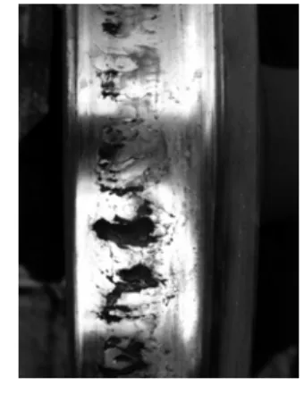
Wheel shelling (Figure 9) is the end result of surface fatigue cracks propagating into the wheel and then linking with other cracks, whereupon a piece of metal spalls from the surface [48,51]. This process leads to high impact forces that damage both the wheel and rail. Wheel replacement due to shelling is a multi-million-dollar per year problem in North America. Broken rails associated with impact forces from shelled wheels are also common, particularly in winter when the rail is under heavy tension, the ballast is frozen and the number of shelled wheels is at its highest. Cracking and shelling of the rail tread may also develop into a broken wheel, leading to an immediate derailment.
Figure 9: A fully shelled wheel tread.
4 METALLURGICAL CONSIDERATIONS
The ability of rail (and wheel) materials to withstand wear, surface and subsurface crack propagation is dependent on the quality of the steel employed [52]. Properties such as hardness, fracture toughness, metallurgical cleanliness and the state of residual stresses are of primary consideration. The next generation of harder and tougher steels is being pursued through improved steel making facilities [53,54,55], head hardening practices [2,56,57,58,59,60] and inspection techniques [61,62].
Large varieties of plain carbon, alloyed and heat treated rail steels are available from rail manufacturers. The general categories for existing rail and wheel metallurgies are given in Table 1. While the development and production of bainitic steels is well underway [2,63,64,65], their performance under heavy haul conditions remains to be established.
4.1 Hardness
One of the most important metallurgical properties of the rail steel is its hardness [66]. It governs wear resistance, rolling contact fatigue resistance and mushrooming (plastic flow) of the railhead.
The wear resistance of the rail steel varies tremendously, depending on the wear mechanism involved. Under abrasive wear such as in rail grinding [67], when the abrasive is much harder than the steel, the relationship between wear and hardness is approximately linear [68]. However, under oxidative wear, hardness is not expected to play a significant role.
The most valued property of hard rail is its resistance to gauge face wear [3,6,7,11,52,66,69,70]. Laboratory tests by Kalousek [21] have shown that in unlubricated wear, head hardened rail steels can reduce gauge face wear rates by a factor of six when compared with Standard rail. Under well-lubricated conditions, the head hardened rail specimens wore at half the rate of the Standard carbon rail specimens. Results from the field tests [71] are less well defined, as the lubrication and/or contamination of the rail cannot be controlled to the same degree as in the laboratory [10,12,27].
4.2 Fracture Toughness
Rail steels with good fracture toughness can inhibit or prevent the occurrence of shelling and internal defects in heavy haul track. Steels with good fracture toughness resist propagation of cracks from both RCF and other types of fatigue [72]. The ability of a material to resist crack growth depends on the propagation Mode (type I, II, or III) [17,28,73,74,75].
The propagation of the contact fatigue cracks and development of the associated spalls and shells are greatly influenced by crack contamination or the entrapment of fluids [23]. It has been widely demonstrated (though little documented) that the presence of water in the cracks over prolonged periods of time cannot be compensated for by further enhancements of fracture toughness. Preventing surface crack initiation represents a more effective way to deal with this problem.
With respect to internal defects, good fracture toughness allows for a reasonable defect detection interval, thereby contributing to the safety of operations. Controlling the morphology of inclusions [76], ensuring favorable residual stresses [72], laboratory and field testing at high [77] and low frequencies and loading rates [78] of developmental rail steels have been utilized to improve the fracture toughness of rail steel.
Micro-alloying elements have been shown to affect the fracture toughness [70,79]. Molybdenum increases fracture toughness while increasing phosphorus has a significant negative impact [72]. Manganese and niobium additions do not appear to influence fracture toughness [80]. Increasing the nitrogen content in steel to 0.0015% enhances the metal’s impact strength at sub-zero temperatures [81].
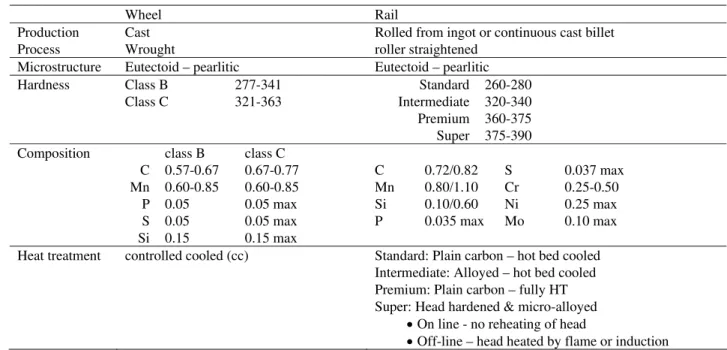
Table 1 - Metallurgical standards for railway wheels and rails
Wheel Rail
Production Process
Cast Wrought
Rolled from ingot or continuous cast billet roller straightened
Microstructure Eutectoid – pearlitic Eutectoid – pearlitic Hardness Class B Class C 277-341 321-363 Standard Intermediate Premium Super 260-280 320-340 360-375 375-390 Composition C Mn P S Si class B 0.57-0.67 0.60-0.85 0.05 0.05 0.15 class C 0.67-0.77 0.60-0.85 0.05 max 0.05 max 0.15 max C Mn Si P 0.72/0.82 0.80/1.10 0.10/0.60 0.035 max S Cr Ni Mo 0.037 max 0.25-0.50 0.25 max 0.10 max Heat treatment controlled cooled (cc) Standard: Plain carbon – hot bed cooled
Intermediate: Alloyed – hot bed cooled Premium: Plain carbon – fully HT Super: Head hardened & micro-alloyed
• On line - no reheating of head
4.3 Microstructure and Cleanliness
Despite increasing interest in bainitic and martensitic rail steels, pearlitic steels continue to prevail for heavy haul railway track. Work is ongoing continually to improve the pearlitic structure, mostly through reductions of the interlamellar spacing and lamella thickness. These refinements have been found to improve wear resistance and fracture toughness properties [79,82,83]. On the other hand, others [84,85] found that by increasing the cementite lamella thickness in hypereutectoid pearlitic steels, wear resistance improved by 20%. In pearlitic steel, increasing prior austenite grain size and lamellae spacing decreases the rate of crack growth [86]. The fine dispersion of copper particles in both lamellae phases can strengthen the pearlitic microstructure without reducing the tensile, ductility and toughness values [69]. Spherodization of the pearlitic microstructure, which may occur in the heat affected zone at welds reduces wear resistance [11].
Rail cleanliness is judged according to the amount and distribution of soft inclusions, hard inclusions and entrapped hydrogen. In the most general terms, soft inclusions increase wear, hard inclusions are associated with sub-surface rolling contact fatigue defects and entrapped hydrogen is responsible for some internal defects.
Wear resistance of rail is adversely affected by soft, manganese sulfide inclusions [87], with clean steel outperforming standard steel by a factor of approximately two. Sulfide inclusions may also contribute to the initiation of RCF surface cracks [13], particularly in the softer grades of rail steel. In either case, plastic flow from asperity contact elongates the sulfide inclusion and effectively forms microscopic cracks within the surface layer, weakening the steels.
Hard inclusions or stringers of inclusions, typically of alumina-silicate composition, have been implicated in the development of sub-surface initiated rolling contact fatigue defects [88,89]. Inclusion stringers are strongly implicated in the formation of vertical split heads [90], deep-seated shells and, in particular, transverse defects from the deep-seated shells. Field testing has shown that the formation of subsurface defects is critically dependent on the “Sugino Index” [91] a measure of the length of oxide stringers. Subsequent work by Clayton [92,93] and others [26,32,94] suggests that the defect rate closely correlates to the so-called “Clayton Number”, which is dependent on the oxide volume fraction, hardness, and Sugino Index. Despite all efforts to improve cleanliness, overloading of the gauge corner can still initiate deep-seated shells in the absence of the inclusions [94].
The ability of hydrogen to form shatter cracks, and thereby cause broken rails, is well known. However, the cleaner the rail, the more precisely the hydrogen level needs to be controlled [95]. It is not surprising then that most rail steel
manufacturers pay very close attention to clean steel making practices [56,63,96].
Improved cleanliness of rail steel substantially reduces the occurrence of defects but cleanliness alone cannot guarantee the absence of defects in the track.
4.4 Residual Stresses
Residual stresses in rail are the result of a) the rail manufacturing process, b) contact stresses due to passing wheels and c) welding. Stresses in as–rolled and fully heat-treated rail are tensile in the head and base and compressive in the rail web, whereas head hardened rail usually exhibits a compressive residual stress in the head [57,97,98]. The type of straightening process affects the residual stress magnitude – characteristically in the order of 100 to 300 MPa [99]. Excessive residual stresses associated with inadequate straightening techniques may contribute to catastrophic rail failure and derailments [100,101]. Numerous destructive and non-destructive methods for measuring residual stresses have been developed. The simplest and most widely employed measurement technique is the saw-cut method [100,102,103].
Work hardening of the surface layer by the passing wheels induces compressive residual stress in the rail-head [104] that can extend up to 15 mm into the rail-head, with harder steels exhibiting a shallower work-hardened depth. These protect the near surface layer by inhibiting the rate and depth of contact fatigue crack propagation [105].
Residual stresses in the vicinity of the weld are distributed in a very complex manner with respect to their magnitude and direction. Flash butt welding introduces high tensile residual stresses that significantly increase the rail susceptibility to horizontal web failures [106].
4.5 Welding
Flash-butt and thermite welds are the most common used in continuously welded track, though gas pressure welds are also applied. Regardless of the welding technique, the primary goal is to match the hardness of the welded joint to that of the parent metal. Improvements to flash butt techniques seek to eliminate defects associated with preheating (spherodization and porosity), flashing (iron oxide inclusions), upset (poor fusion, dendritic structure) and post-heating (martensite, unmatched hardness) [106,107]. Problems with thermite welds include lack of fusion and porosity [108,109]. Although these are the same problems that have plagued track maintenance engineers for the last few decades [45], increasing axle loads, changes to rail metallurgy, shorter maintenance windows and demands for improved weld quality ensure that research into improved welding processes will continue into the foreseeable future [46,110].
A major problem with current rail maintenance technology is that a rail defect is removed and replaced with a 6 m rail plug and two more welds. Wide gap welds [111] that span
70 mm offer the hope of eliminating rail plugs and reducing the total number of welds in track.
5 CONTACT MECHANICS CONSIDERATIONS Improved rail metallurgy may provide greater freedom in the quest to engineer optimal wheel and rail profiles. The design of profiles for a given rail operation has always required a compromise between three main parameters: 1. Contact stress – conformal profiles reduce contact
stress, which minimizes the possibility of contact fatigue and wear. On the other hand, conformal profiles may be subject to large spin creepages, especially in tangent track. This creepage contributes to wear and short pitch corrugation development. 2. Wheelset steering – a non-conformal, single point
contact provides the greatest steering forces in curves, but on heavy haul railways overloads the rail gauge corner.
3. Effective conicity – wheel/rail profile combinations that compromise between contact stress and steering often develop a high effective conicity, which is a precursor to truck hunting.
If improvements in rail metallurgy are accompanied by advances in wheel steel technology, we may significantly increase the range of allowable contact stresses. An exciting possibility is then available - with improved trucks, profile selection and control, and grinding implementation, we may one day be able to safely employ a single point (conformal) high rail contact strategy on heavy haul systems. The resulting improvements in steering and stability should provide significant reductions in fuel consumption and increases in both wheel and rail life. 6 OTHER PERSPECTIVES
Reduction in rolling contact fatigue, wear and defects are achieved by minimizing contact stress, traction forces, and ratcheting. The contributions of metallurgy to increasing rail and wheel life have been addressed in §4. However lubrication, bogie improvements and rail grinding also contribute to increases in wheel and rail life, especially when implemented as part of an overall system strategy. 6.1 Lubrication and Metallurgy
At any level of creepage and contact pressure at the wheel/rail interface, friction is largely controlled by the composition of the interfacial layer [4,19]. Depending on the layer thickness and the amount of brakeshoe debris, sand, organic residues, moisture, greases, oils, wear debris and other environmental contaminants in the layer, the effective friction coefficient can range between 0.1 and 0.7 [6,8].
The application of lubricants (greases, oils, solid sticks) to the wheel-flange and/or gauge-face of the rail provides the most dramatic evidence of wear reduction associated with lubrication. Laboratory tests have shown that properly and
consistently applied lubrication to reduce friction to 0.15 or lower, can reduce wear of the high rail by a factor of 1000 of that in unlubricated conditions [8]. Subsequent field-testing showed that actual results ranged from 1/5 to 1/20th, when comparing wear of the high rail under lubricated vs. unlubricated conditions [21].
Managing the friction coefficient at the top of the rail has emerged in the last decade as a feasible means for controlling wear and contact stresses in rails. The “untreated” top-of-rail friction value often reaches 0.55 [44] or greater and is associated with high rates of wear, fatigue and plastic flow of both rail and wheel.. High top-of-rail friction is also responsible for large lateral forces that spread the high and low rails in curves. A high L/V (lateral/vertical) ratio is a primary factor in derailments caused by either climbing of the wheel over the high rail (wheel climb) or outward rotation of the low rail (low rail rollover derailments) [112].
As seen in Figure 3, the shakedown limit rapidly decreases (and associated rolling contact fatigue rates increase), for friction levels greater than 0.3. Controlling top-of-rail friction to about 0.3, in combination with improved metallurgy, provides a high degree of resistance to surface plastic flow. Consequently, cracking and shelling are inhibited and the number of rail breaks reduced. Because of the concern with maintaining locomotive adhesion, railways have been reluctant to place any friction reducing substances on the top of the rail. However, significant developments have been made in friction modifiers, including the formulation of solid stick flange and tread friction control products [19], and locomotive borne lubrication systems [113,114].
6.2 Bogie improvements and Metallurgy
Improved bogies [115,116] have been shown to reduce wheel/rail interface traction forces, wear [117] and RCF damage to wheels and rails. At the same time, harder and cleaner steels are demonstrating significantly greater resistance to contact fatigue [24,118]. Taken together, advanced bogies with improved metallurgies may permit more aggressive asymmetric profiling of rails, reducing creepage by maximizing steering forces. In the past, steering was always compromised by the inability of rail steels to withstand the higher contact stresses that were required. Today’s premium steels may enable us to employ wheel/rail profile combinations with higher (but acceptable) contact stresses and improved steering.
6.3 Grinding and Metallurgy
Rail grinding has played a major role in increasing the life of all rail [67,119,120,121,122]. As various field tests have demonstrated, even though improved metallurgies may considerably improve resistance to both wear and fatigue, worn or improperly ground rail encounters an unfavorable contact stress distribution that culminates in rolling contact fatigue [92]. Profile grinding of the rail is required to promote a healthy wheel/rail contact geometry [26,67].
Advances in grinding strategies, including the application of multiple tangent rail profiles and implementing preventive grinding should be important parts of any attempt to improve rail life. Fine-tuning metal removal rates to meet the specific curvature/metallurgy/environmental needs of the treated rail will enable rail grinding to further contribute to both reduced rail maintenance costs and increased rail life.
7 MEETING THE CHALLENGE
The last generation of metallurgists and steel producers provided us with a colorful variety of pearlitic steels to meet any set of heavy haul operating conditions. Rail manufacturers continue to explore novel micro-alloying and production techniques for squeezing further improvements from pearlitic steels. With the exception of a few special track work components, the current generation of pearlitic steels will most likely serve us well into the first two decades of the next century.
As axle loads rise toward the 50 ton level, even the cleanest and hardest (≈380 BHN) pearlitic steels will succumb to plastic flow, surface fatigue and internal defects. To meet these demands, the development of harder rail steels is underway. Ultra-High-Carbon, Austenitic-Mn and maraging rail structures are being considered but the most promising candidates are eutectoid and low carbon bainitic steels. Unfortunately, the cost of high alloy steels is likely to be appreciably higher (e.g. 40%) than today’s standard metallurgies. Also, before any new metallurgy will be widely adopted, it must prove resistant to web cracking during roller straightening, demonstrate suitable weldability to existing metallurgies and exhibit a compatible thermal expansion coefficient.
Demands for higher rail life under conditions of shrinking maintenance windows have and will be met through a systems approach. Although this paper has focussed on metallurgy and contact mechanics, it should be clear that other elements such as lubrication, bogie improvements and rail grinding can provide significant contributions to improving wheel and rail life.
8 ACKNOWLEDGEMENTS
Dr. Grassie is grateful to Loram Maintenance of Way Inc. for sponsoring his contribution to this paper. However, the paper reflects the views of the three authors, which are not necessarily those of Loram. The authors also wish to express their appreciation for the assistance of Ms. Eva Sharpe in preparing the manuscript.
9 REFERENCES
1. Kobayashi I, Majima A, Iwabuchi Y, Discussion on the Steel for a Rail Produced in the 1880’s, Kushiro Kogyo Koto Senmon Gakko Kiyo Research Rpts, Kushiro Tech College, 1991, 25, pp. 43-48.
2. Jones J A, Perlman A B, Orringer O, Tailoring Heat Treatment and Composition for Production of
On-Line Head-Hardened Bainitic Rail, 39th Tech Working and Steel Processing Conf Proc, 1997, XXXV, pp. 1029-1036.
3. Shur E A, et al, The Variation of Rail Damage with the Increase of Axle Load, IHHA Railway Conf, Montreal Canada, Jun 1996, pp. 7.47-7.52.
4. Broster M, Pritchard C, Smith D A, Wheel-Rail Adhesion: Its Relation to Rail Contamination on British Railways, Wear, 1974, 29, pp. 309-321. 5. Zakharov S, Komarovsky I, Zharov I, Wheel Flange
Rail Head Wear Simulation, Wear, Mar 1998, 215 (1-2), pp. 148-24.
6. Kumar S, Alzoubi M F, Allsayyed N A, Wheel/Rail Adhesion Wear Investigation Using a Quarter Scale Laboratory Testing Facility, Proc of the IEEE ASME Joint Railroad Conf, Piscataway USA, 1996, pp. 247-254.
7. Tyfour W R, Beynon J H, Effect of Rolling Direction Reversal on the Wear Rate and Wear Mechanism of Pearlitic Rail Steel, Tribology Int’l, Dec 1994, V27 (n6), pp. 401-412.
8. Kalousek J, Lubrication: Its Various Types and Effects on Rail / Wheel Forces and Wear, Rail and Wheel Lub Symp, Sept 1981.
9. Bolton P J, Clayton P, McEwen I J, Wear of Rail and Tire Steels Under Rolling/Sliding Conditions, American Society of Lub Engs Conf, San Francisco USA, Aug 1980.
10. Eng O, Herbst W, On the Assessment of the Resistance to Wear of Rail Steels by Means of Wear Measurements in Track Curves, Rail Int’l, Apr 1981, pp. 164-168.
11. Fegredo D M, Shehata M T, Kalousek J, The Effect of Progressive Minor Spheroidization on the Dry Wear Rates of a Standard Carbon and a Cr -Mo Alloy Rail Steel, Wear, 1993, 161 (1-2), pp. 29-40. 12. McEwen I J, Harvey R F, Full-Scale Wheel-on-Rail
Wear Testing: Comparisons with Service Wear and a Developing Theoretical Predictive Method, American Society of Lub Engs Conf, Hartford USA, Oct 1983.
13. Grassie S L, Kalousek J, Rolling Contact Fatigue of Rails: Characteristics, Causes and Treatments, 6th IHHA Conf, Capetown, 1997, pp. 381-404.
14. Ghonem H, Kalousek J, Study of Surface Crack Initiation Due to Biaxial Compression/Shear Loading, Engng Fracture Mech, 1988, 30 (5), pp. 667-683.
15. Johnson K L, The Mechanics of Plastic Deformation of Surface and Subsurface Layers in Rolling and Sliding Contact, Material Science Forum: The Role of
subsurface Zone in Wear of Materials, Trans Tech Publications, 1988, pp. 33-40.
16. Kapoor A, Williams J A, Shakedown Limits in Rolling-Sliding Point Contacts on an Anisotropic Half-Space, Wear, Jan 1996, 1 (n1-2), pp. 256-260. 17. Bold P E, Brown M W, Allen R J, Shear Mode Crack
Growth and Rolling Contact Fatigue, Wear, 144 (1991), pp. 307-317.
18. McDowell D L, Stress State Dependence of Cyclic Ratcheting Behavior of Two Rail Steels, Int’l J of Plasticity, 1995, II (4), pp. 397-421.
19. Kalousek J, et al, The Benefits of Friction Management – A Third Body Approach, World Conf on Railway Research, Colorado USA, Jun 1996. 20. Inoue Y, Satoh Y, Kashiwaya K, Rolling Contact
Fatigue Fracture of Conventional Line Rail, J of the Society of Materials Science, Japan, Jul 1991, 40 (454), pp. 797-803.
21. Kalousek J, Wear and Contact Fatigue Model for Railway Rail, National Research Council of Canada, 1986, 27491 (TR-WE-50).
22. Way S, Pitting Due to Rolling Contact, J Applied Mech, 2, 1935, pp. 49-56.
23. Bower A F, The Influence of Crack Face Friction and Trapped Fluid on Surface Initiated Rolling Contact Fatigue Cracks, J of Tribology, Oct 1988, 110, pp. 704-711.
24. Muster H, et al, Rail Rolling Contact Fatigue. The Performance of Naturally Hard and Head-Hardened Rail in Track, Wear, 1996, 191, pp. 54-64. 25. Hellier A K, McGirr M B, Corderoy A J H, A Finite
Element and Fatigue Threshold Study of Shelling in Heavy Haul Rails, Wear, 144 (1991) pp. 289-306. 26. Kalousek J, Igwemezie J O, Shell-Like Defects and
Microgeometry of Grinding, Proc of the Int’l Symp on Rail Steels-Developments Manufacturing and Performance, Montreal Canada, Oct 1992, IV, pp. 139-145.
27. Steele R K, Reiff R P, Rail: Its Behavior and Relationship to Total System Wear, 2nd IHHA Railway Conf, Sept 1982, Colorado Springs USA, pp. 227-276.
28. Jeong D Y, Tang Y H, Orringer O, Damage Tolerance Analysis of Detail Fractures in Rail, Theoretical and Applied Fracture Mechanics, Netherlands, Dec 1997, 28 (2), pp. 109-115.
29. Kuo C H, Keer L M, Steele R K, Simulation of the Vertical Split Head Failure in Rails, Int’l J Solids and Structures, 30 (16), 1993, pp. 2177-2197.
30. Mayville, R A, Metallurgical and Fracture Surface Analysis of Vertical Split Head Defects, Rpt to US Dept of Transport.
31. Skinner D H, Judd P A, A Metallographic Study of Fatigue Defects in Rails, AIM 34th Annual Conf, Queensland, May 1981, pp. 208-212.
32. Orringer O, Some Suggestions for Adjusting Rail Test Schedules to Reflect Track Characteristics, Maintenance, Traffic, and Weather, Proc of the Int’l Symp on Rail Steels Developments Manufacturing and Performance, Montreal Canada, Oct 1992, V, pp. 149-159.
33. Grassie S L, Kalousek J, Rail Corrugation: Characteristics, Causes and Treatments, Proc Inst Mech Engrs, 1993, 207, pp. 57-68.
34. Knothe K, Grassie S L, Modelling of Railway Track and Vehicle/Track Interaction at High Frequencies, Vehicle System Dynamics, 1993, 22, pp. 209-262. 35. Mair R I, Jupp R A, Groenhout R, Characteristics and
Control of Long Pitch Rail Corrugation at Heavy Axle Loads, Rail Research Papers, Vol. 1, BHP MRL, Australia, 1987.
36. Mair R I, Natural Frequency of Rail Track and Its Relationship to Rail Corrugation, Civil Engng Trans, Instn of Engs, Australia, 1977.
37. Kalousek J, Thorough Lubrication and Light Grinding Prevents Rail Corrugations. Proc. of Rail and Wheel Lub Symp, Memphis USA, Jun 1987. 38. Devine T J, Daniels L E, Blume N, Rail Corrugation
Investigations at FAST: Dec 1979 Through Aug 1981. Conf on FAST Engng, Rpt no FRA/TTC-82/01, pp 165-174.
39. Grassie S L, Elkins J A, Rail Corrugation on North American Transit Lines, 29, 1998, pp.5-17.
40. Bower A F, Johnson K L, Plastic Flow and Shakedown of the Rail Surface in Repeated Wheel-Rail Contact, Wear, Apr 1991, 144 (n1-2), pp. 1-18. 41. Jones C P, et al, The Effect of Strain Hardening on
Shakedown Limits of a Pearlitic Rail Steel, Proc of the Instn of Mech Engs Part F, J of Rail and Rapid Transit, 1997, 211 (2), pp. 131-140.
42. Steele R K, Joerns M W, Plastic Deformation and its Relationship to Rail Performance, Rail Steels for the 21st Century, Warrendale Iron and Steel Society, 1995. 43. Tanvir M A, Temperature Rise Due to Slip Between
Wheel and Rail – An Analytical Solution for Hertzian Contact, Wear, 1980, 61, pp. 195-308. 44. Iwand H C, Stone D H, Moyar G J, A Thermal and
Metallurgical Analysis of Martensite Formation and Tread Spalling During Wheel Skid, Rail Transportation, ASME, 1992, RTD-Vol. 5.
45. Hauser D, Welding of Railroad Rails – A Literature and Industry Survey, Rail Steels – Development, Processing and Use, ASTM 1978, ASTMSTP 644, pp. 118-141.
46. Shitara H, et al, Study of Rail Welding with High Carbon Welding Materials, Proc of the Int’l Symp on Rail Steels - Developments Manufacturing and Performance, Montreal Canada, Oct 26-27 1992, IV, pp. 121-128.
47. Cantera F, Investigation of Wheel Flange Wear on the Santander REVE Rail – A Case Study, Wear, Apr 1993, 162-164 (pt B), pp. 975-979.
48. Magel E, Kalousek J, Martensite and Contact Fatigue Initiated Wheel Defects, 12th Int’l Wheelset Congress, Qingdao China, Sept 1998.
49. Jergeus J, Martensite Formation and Damage around Railway Wheel Flats, 6th IHHA Conference, Cape Town 1997, 2, p. 889-903.
50. Stone D H, et al, Theoretical and Experimental Study of Wheel Spalling in Heavy Haul Hopper Cars, 10th Int’l Wheelset Congress, Sydney Australia, 1992.
51. Kalousek J, Hornady J H, Caldwell W N, Wheel Shelling problems on the Canadian National Railways’ British Columbia Northline, 9th Int’l Wheelset Congress, Montreal Canada, Sept. 1988. 52. Clayton P, et al, Recent Research on Wear,
Deformation and Fatigue of Steels in Rolling Contact, Proc of the Int’l Symp on Rail Steels Developments Manufacturing and Performance, Montreal Canada, Oct 1992, V, pp. 161-174.
53. Bramfitt B L, Wirick D P, Cross R L, Rail Head Hardening Facility at Pennsylvania Steel Technologies, Iron and Steel Engineer, May 1996, 73 (n 5), pp. 33-36.
54. Pan A V, Kirichkov A A, Shumilin E N, Rail Production at the Nizhny Tagil Metallurgical Works (NTMK), Proc of the Int’l Symp on Rail Steels-Developments Manufacturing and Performance, Montreal Canada, Oct 1992, I, pp. 17-25.
55. Cordova V, Rails from Rounds – A First” The Production of Rails from Continuously-Cast Rounds, Rail Steels for the 21st Century, Warrendale Iron and Steel Society, 1995.
56. Moser A, Prskawetz G, New Rail Manufacturing Technology at Voest-Alpine Schiene Ges.M.B.H., Proc of the Int’l Symp on Rail Steels Developments Manufacturing and Performance, Montreal Canada, Oct 1992, I, pp. 3-9.
57. Fata R G, et al, A Numerical Model for Estimation of Temperature-Time History and Residual Stress in
Head-Hardened Rails, 39th Tech Working and Steel Processing Conf Proc, 1997, XXXV, pp. 1037-1044. 58. Kataoka, et al, In-Line Heat Treated THH-Rails,
Proc of the Int’l Symp on Rail Steels-Developments Manufacturing and Performance, Montreal Canada, Oct 1992, I, pp. 11-16.
59. Ueda M, et al, NKK New Premium Rail, Warrendale Iron and Steel Society, USA, 1991, pp. 185-190. 60. Bramfitt B L, Wirick D P, Cross R L, Advanced
In-Line Head Hardening of Rail, Rail Steels for the 21st Century, Warrendale Iron and Steel Society, 1995. 61. Davis J A, Uhrin R G, Overview of Current Rail
Inspection Program at Bethlehem Steel, Proc of the Int’l Symp on Rail Steels Developments Manufacturing and Performance, Montreal Canada, Oct 1992, I, pp. 27-31.
62. Vogel D E, Material Testing of Premium Rail at Pennsylvania Steel Technologies, Rail Steels for the 21st Century, Warrendale Iron and Steel Society, 1995. 63. Bramfitt B L, Symposium Review – Rail Steels for
the 21st Century, Iron and Steelmaker, Feb 1995, 22 (n2), pp. 33-35.
64. Steele R K, Next Generation Rail Steels, ARM Rail Maintenance Seminar, April/May 1996, 1 (II) pp. 1-20. 65. Steel R K, Alloying Considerations for Heat
Treatment of Rail to a Lower Bainite Microstructure, 39th Mech Working and Steel Processing Conf Proc, Iron & Steel Society of AIME, Warrendale USA, 1997, XXXV, pp. 997-1006. 66. McLean M, Harder Heads Reduce Rail Wear,
Railway Gazette Int’l, Sept 1997, 153 (n 9), p. 605. 67. Kalousek J, Sroba P, Hegelund C, Analysis of Rail
Grinding Tests and Implications for Corrective and Preventive Grinding, 4th IHHA Railway Conf, 1989, Brisbane Australia, pp. 193-204.
68. Khruschov, MM, Principles of Abrasive Wear, Wear 28, 1974, 69-88
69. Khalid F A, et al, The Role of Microalloying and Copper Additions on the Microstructure and Mechanical Properties of Eutectoid Rail Steels, Dr. A.Q. Khan Research Laboratories, Kahuta Pakistan, 1994, pp. 401-410.
70. Singh U P, Singh R, Jha S, Influence of Microalloying on Fracture Toughness and Wear Resistance of Rail Steel, Scandinavian J of Metallurgy, Denmark, Aug 1995, 24 (4), pp. 180-186. 71. Reiff R P, Garcia G, An Update on Rail and Field
Weld Tests Under Heavy Axle Loads, Rail Steels for the 21st Century, Warrendale Iron and Steel Society, 1995.
72. Olund P, Crack Propagation Properties and Fracture Toughness in Rail Steel – A Literature Review, Instn for Metallforskning, Forskningsrapport, Sweden, Oct 1994, p. 84.
73. Bogdanski S, Olzak M, Stupnicki J, Numerical Stress Analysis of Rail Rolling Contact Fatigue Cracks, Wear, Jan 1996, pp. 14-24.
74. Hellier A K, et al, Fatigue of Head-Hardened Rail Steel Under Mode III Loading, Int’l J of Fracture, Australia, Jan 1990, 42m (1), pp. R19–R23.
75. Singh U P, Singh R, Banerjee S, Fatigue Crack Growth Rate and Fracture Toughness of Rail Steels, Scandinavian J of Metallurgy, Denmark, 1995, 24 (5-6), pp. 237-241.
76. Liu C D, Bassim M N, St Lawrence S, Dependence of the Fatigue Limit of Rail Steels on Stress Intensity Factor Near Inclusions, Engng Fracture Mechanics, USA, Jan 1995, 50 (2), pp. 301-307.
77. Bokuvka O, Nicoletto G, Palcek P, Materials Evaluation For Rail Transportation: High-Frequency Fatigue Testing, Associazione Italiana de Metallurgia, Italy, Sept 1992, pp. 123-129.
78. Cheng Y, Chen D, Nogata F, Fatigue Behavior of a Rail Steel Under Low and High Loading Rates, Fatigue Fracture Engng Material Structures, Jan 1994, 17 (1), pp. 113-118.
79. Singh U P, Singh R, Wear Investigation of Wheel and Rail Steels Under Conditions of Sliding and Rolling-Sliding Contact with Particular Regard to Microstructural Parameters, Wear, Nov 1993, 170 (1), pp. 93-99.
80. Parsons D E, Munro D A, Ng-Yelim J, Vanadium/Nitrogen Modification of 1% Cr and Cr-Cb Rail Steels, Canadian Metallurgy Quarterly, Vol. 22, No.4, 1983, pp.475-483.
81. Nesterov D K, et al, Effect of Nitriding on the Quality of Rail Steels, Russia Metallurgy, Russia, 1993, 3, pp. 158-165.
82. Gomes M G M, et al, Effects of Microstructural Parameters on the Mechanical Properties of Eutectoid Rail Steels, Materials Characterization, Elsevier Sequoia, Jul 1997, 39 (1), pp. 1-14.
83. Perez-Unzueta A J, Beynon J H, Microstructure and Wear Resistance of Pearlitic Rail Steels, Wear, April 1993, 162-16 (A), pp. 173-182.
84. Ueda M, et al, Development of Hypereutectoid Steel Rails for Heavy Haul Railways, 6th IHHA Conf, Cape
Town, 1997, pp. 355-369.
85. Masahauru U, et al, Development of Hypereutectoid Steel Rails for Heavy Haul Railways, Proc. 6th IHHA Conf, Capetown, 1997.
86. das Grajas M, da Fonseca G M, Effects of Microstructural Parameters on the Mechanical Properties of Eutectoid Rail Steels, Material Characteristics, Elsevier Sequoia, 1997, 39 (1), pp. 1-14.
87. Hornaday J, The Effects of Non-Metallic Inclusions on The Durability of Rail in Heavy-Haul Service, Proc of the Int’l Symp on Rail Steels-Developments Manufacturing and Performance, Montreal Canada, Oct 1992, II, pp. 63-66.
88. Sugino K, Kageyama H, Urashima C, Metallurgical Improvement of Rail for the Reduction of Rail-Wheel Contact Fatigue Failures, Wear 144 (1991) pp. 319-328.
89. Carpenter G F, Steele R K, Markase M J, Effects of Inclusion Content on Fatigue Performance of Rail Steels, Proc of the Int’l Symp on Rail Steels Developments Manufacturing and Performance, Montreal Canada, Oct 1992, II, pp. 49-56.
90. Savage E I and Steele R K, A Failure Analysis of Railroad Rail, ASM Metals Park, Ohio, 44073 1978 pp 29-48
91. Sugino K, Kageyama H, Newell H W, Detection Method for Harmful Inclusions in Rail Steels, AREA Bulletin, 1988, 716 (89), pp. 230-259.
92. Hannafious J, Clayton P, The Effect of Metallurgy and Grinding on Subsurface Initiated Fatigue of Rails in a 39 kip Wheel Load Experiment at FAST, Rail Steels for the 21st Century, AIME ISS Mech. Working and Steel Proc Conf, Baltimore, Oct 1994. 93. Li H, Clayton P, A Statistical Analysis of the Oxide
Content of Rail Steel, Rail Steels for the 21st Century, Warrendale Iron and Steel Society, 1995. .
94. Sugino K, et al, Metallurgical Investigation of Transverse Defect in Worn Rails in Service, Wear 191, 1996, pp. 141-148
95. Fruehan R J, A Review of Hydrogen Flaking and Its Prevention, ISS Transactions, Aug 1997, pp. 61-69. 96. Schmedders H, Wick K, A Metallurgical Process for
the Production of a Very Clean Rail Steel, Proc of the Int’l Symp on Rail Steels-Developments Manufacturing and Performance, Montreal Canada, Oct 1992, II, pp. 35-48.
97. George B L, MacDonald J B, Kokoska F W, Residual Stresses in Off-Line Head Hardened Rails, Proc of the Int’l Symp on Rail Steels Developments Manufacturing and Performance, Montreal Canada, Oct 1992, III, pp. 79-91.
98. Varney B E, Farris T N, Mechanics of Roller Straightening, 39th Tech Working and Steel Processing Conf Proc, Iron & Steel Society of AIME, Warrendale USA, 1997, XXXV, pp. 1111-1121.
99. Esveld C, Modern Railway Track, MRT Productions, West Germany, 1989.
100. Igwemezie J O, Kennedy S L, Gore N R, Residual Stresses and Catastrophic Rail Failure, ARM Rail Maintenance Seminar, USA, April 30/May 1 1996, 1 (III), pp. 1a-8a.
101. Volegov I F, Polyakov A P, Kolmogorov S V, Mathematical Model of Rail Straightening and Experimental Estimation of its Adequacy, J of Materials Processing Tech, Jan 1994, 40 (n1-2), pp. 213-218.
102. Bramfitt B L, Residual Stresses In Rail - Measured by the Web Sawcut Method, Proc of the Int’l Symp on Rail Steels Developments Manufacturing and Performance, Montreal Canada, Oct 1992, III (29), pp. 69-78.
103. Wineman S J, McClintock F A, A Saw-Cutting Test for Estimating Stress Intensity at a Rail Web Crack Due to Residual Stresses, Theoretical Applied Fracture Mechanics, Mar 1990, 13 (1), pp. 21-27. 104. Makoto I, Noritsugi A, Experimental Study on
Rolling Contact Fatigue from the Aspect of Residual Stress, Wear, 1996, 191, pp. 65-71.
105. Orringer O, et al, Residual Stress and its Consequences on Both Sides of the Wheel-Rail Interface, Wear, 1996, 191, pp. 29-34.
106. Griffin K, Near-Surface Residual Stresses for Rail Steels and Flash-Butt Welds, Proc of the Int’l Symp on Rail Steels Developments Manufacturing and Performance, Montreal, Canada, Oct. 1992, III, pp. 93-102.
107. Panaitescu S, Oanca O, Vestemean C N, Drive, Control and Monitoring of Iron Rail Butt Resistance Welding, ASM Int’l Europe, Mar 1997, pp. 125-144.
108. Jha B, Thermite Welding of Rail Steel. (Dissertation), Dissertation of Abstracts Int’l, Illinois Instn of Technology, Nov 1990, 51m (5), p. 257. 109. Jha B, et al, A Numerical Evaluation of Heat
Transfer During the Thermite Welding Process: Effect of Process Parameters, Proc of the Int’l Symp on Rail Steels-Developments Manufacturing and Performance, Montreal Canada, Oct 1992, IV, pp. 111-119.
110. Uchino K, et al, Development of Automatic Rail Welding Process, Proc of the Int’l Symp on Rail
Steels-Developments Manufacturing and Performance, Montreal Canada, Oct 1992, IV, pp. 129-137.
111. Sun J, Improved Rail Welding – Wide-Gap Welds for Heavy Haul, 4th Annual AAR Research Review, Colorado USA, 1998, p. 211-222.
112. Elkins J A, Wilson N G, Rail Rollover Derailments Caused by Large Truck Turing Moments on Improperly Lubricated Track, ASME, 1989.
113. Kramer, J. Rail Lubrication: multiple choice, Railway Tracks and Structures, Aug 1995, p 14-15. 114. Runyon R S, Top of Rail Lubrication, ARM
Wheel/Rail Interface Seminar, Chicago, May 1997. 115. Scales B T, Review of Freight Car Bogie Design and
Performance, IHHA Conf on Freight Car Truck / Bogies, Jun 1996, pp. 1.1-1.14.
116. Scheffel H, Tournay H M, Frohling R D, The Evolution of the Three-Piece Freight Car Bogie to Meet Changing Demands in Heavy Haul Railroads in South Africa, IHHA Conf on Freight Car Trucks / Bogies, Jun 1996, pp. 1.15-1.29.
117. Swenson C A, Scott R T, Effect of Locomotive Radial Steering Bogies on Wheel and Rail Wear, Proc of the IEEE ASME Joint Railroad Conf, Piscataway NJ USA, 1996, pp. 91-100.
118. Wirick D P, Martens J H, Overview of Rail Manufacturing Changes for Improved Rail Fatigue Performance, Proc of the Int’l Symp on Rail Steels-Developments Manufacturing and Performance, Montreal Canada, Oct 1992, I, pp. 57-62
119. Kondo K, Yoroizaka K, Sato Y, Cause, Increase, Diagnosis, Countermeasures and Elimination of Shinkansen Shelling, Wear, Jan 1996, 191 (1-2), pp. 199-203.
120. Worth A W, Hornaday J R, Richards P R, Prolonging Rail Life Through Rail Grinding, Proc of the 3rd IHHA Railway Conf, 1986, pp. 106-116.
121. Hannafious, J and Clayton, P, The Effect of Metallurgy and Grinding on Subsurface Initiated Fatigue of Rails in a 39 kip Wheel Load Experiment at FAST, Rail Steels Symposium, Iron and Steel Society, 1994, pp 105-114
122. Steel R K, The Effect of Metal Removal, Steel Cleanliness and Wheel Load on the Fatigue Life of Rail, Wear 144 (1991), pp.71-87.